EHRLE HSC 723 Series User manual

Hochdruck-Reinigungs-Systeme High-Pressure-Systems
1
Betriebsanleitung - Operating Instruction
Stationäre Hochdruckreiniger
Heißwasser
Stationary High Pressure Cleaners
Hotwater
Typen - Series
HSC 723 (-ST) - HSC 1140 (-ST) - HS 1240 (-ST) - ölbeheizt/oilheated
HSC 840 (-ST) - HSC 1140 (-ST) - elektrisch beheizt/elect. heated
HSC 1140 -ST - gasbeheizt / natural gas-heated
2. Au age 06.10.2010 - 2. Edition 06.10.2010 © EHRLE GmbH 2010. Alle Rechte vorbehalten.
VORSICHT: Zur Inbetriebnahme der Hochdruckreiniger die Betriebsanleitung beachten.
WARNING: Observe Operating Instruction for commissioning the High Pressure Cleaners.

Hochdruck-Reinigungs-Systeme High-Pressure-Systems
65
Operating Instruction
for
Stationary High Pressure Cleaners
Hotwater
Series
HSC 723 (-ST) - HSC 1140 (-ST) - HS 1240 (-ST) - ölbeheizt/oilheated
HSC 840 (-ST) - HSC 1140 (-ST) - elektrisch beheizt/elect. heated
HSC 1140 -ST - gasbeheizt / natural gas-heated

Hochdruck-Reinigungs-Systeme High-Pressure-Systems
66
Preface
With purchasing the EHRLE High Pressure Cleaner you are the owner of a high
quality product. Besides the outstanding features our High Pressure Cleaners are:
• Ease of operation
• Reliable
• Environmentally friendly
Our High Pressure Cleaners meet national and international safety standards and
have received the approval of international agencies and laboratories. All High
Pressure Cleaners meet the European Conformity CE Standard.
This operating instruction contains the operation, maintenance and repair for the
stationary High Pressure Cleaner series:
• HS 623, HS 840, HS 1040, HS 1240, HSC 623, HSC 1040
• HSE 800, HSE 1000,
• HSG 1240.
The WARNINGS, CAUTIONS and NOTES in this operating instruction are de ned as
follows:
Warning precedes operating procedures, instructions, etc., which,
if not strictly observed, could result in personal injury or loss of life.
Warning precedes also, when device misuse could result in personal
injury or loss of life.
Attention precedes operating procedures, instructions, etc., which, if
not strictly observed, could result in damage to the High Pressure
Cleaner. Attention precedes also, when device misuse could result in
damage to the High Pressure Cleaner.
Note precedes or follows, when additional information is presented.
For the High Pressure Cleaner commissioning and operation observe
the operating instruction.
Only specially trained and quali ed personal are allowed to perform
High Pressure Cleaner installation, maintenance and repair.
ATTENTION
NOTE
WARNING
WARNING

Hochdruck-Reinigungs-Systeme High-Pressure-Systems
67
The gas red High Pressure Cleaner HSG 1240 is equipped with a gas burner from
manufacturer HANSA (original equipment manufacturer). The scope of delivery of the
series HSG includes the “Installation and Operating Instructions” from HANSA.
Observe the “Installation and Operating Instructions” for the gas burner.
The gas red High Pressure Cleaner HSG 1240 is certi ed by the DVGW (Deutscher
Verein des Gas- und Wasserfaches).
CE-Number: CE 0085AR0179.
Address
DVGW Deutscher Verein des Gas- und Wasserfaches
Technisch-Wissenschaftliche Vereinigung
Postfach 14 03 62
53058 Bonn
Josef-Wimmer-Str. 1-3
53123 Bonn
The circuit diagrams in section 4 show the wiring of the general standard High
Pressure Cleaners. The detailled device speci c information shows the circuit diagram
contained in the terminal box of every delivered High Pressure Cleaner.

Hochdruck-Reinigungs-Systeme High-Pressure-Systems
68
Table of content
Technical description
1 Technical description .......................................................................................72
1.1 General information ........................................................................................72
1.2 Utilization ........................................................................................................74
1.3 Total view of stationary High Pressure Cleaner ..............................................74
1.4 Technical data .................................................................................................78
1.4.1 Technical data for series HS 623, HS 840 and HS 1040................................. 78
1.4.2 Technical data for series HS 1240 and HSG 1240 .........................................80
1.4.3 Technical data for series HSE 800 and HSE 1000 .........................................81
1.5 General function of High Pressure Cleaner ....................................................82
1.5.1 General function of series HS .........................................................................82
1.5.2 General function of series HSE........................................................................84
1.5.3 General function of series HSG ......................................................................86
Commissioning and operation
2 Commissioning and operation ........................................................................88
2.1 Precautions to prevent accidents ....................................................................88
2.2 Installation of the High Pressure Cleaner .......................................................89
2.2.1 General ...........................................................................................................89
2.2.2 Locating the High Pressure Cleaner central unit ............................................91
2.2.3 Installing the High Pressure Cleaner central unit ............................................94
2.2.4 Electrical connection for the High Pressure Cleaner ......................................96
2.2.5 Water supply connection for the High Pressure Cleaner ................................98
2.2.6 Installing the fuel oil supply for series HS .......................................................99
2.2.7 Installing the natural gas supply for series HSG ...........................................101
2.2.8 Installing the detergent supply ......................................................................102
2.2.9 Installing the high pressure pipes .................................................................102
2.2.10 Installing the cleaning equipment ..................................................................103
2.2.11 Installing the remote control ..........................................................................103
2.2.12 Installing the self service coin acceptor ........................................................104
2.2.13 Installing the chimney for series HS and HSG ..............................................105
2.3 Commissioning and operation ......................................................................106
2.3.1 Before rst commissioning ............................................................................106
2.3.2 Oil burner check and adjustment for series HS ............................................106
2.3.3 Gas burner check and adjustment for series HSG .......................................107
2.3.4 Commissioning the High Pressure Cleaner ..................................................108
2.3.5 Operating the High Pressure Cleaner via self service coin acceptor ............112
2.4 Applying the cleaning detergent (chemical) ..................................................112

Hochdruck-Reinigungs-Systeme High-Pressure-Systems
69
2.5 Decommissioning the High Pressure Cleaner ...............................................113
2.6 Guidelines, Regulations, Certi cates ............................................................114
2.6.1 Guidelines for pressure vessels and steam boiler regulation ........................114
2.6.2 Guidelines for liquid sprayers ........................................................................114
2.6.3 Manufacturer tests and certi cates ...............................................................115
2.6.4 Emissions regulations ...................................................................................115
2.6.5 Notes for place of use ...................................................................................115
Maintenance and Repair
3 Maintenance and repair .................................................................................116
3.1 Care for the High Pressure Cleaner ..............................................................116
3.1.1 Cleaning the High Pressure Cleaner .............................................................116
3.1.2 Anti freeze protection ....................................................................................116
3.2 Maintenance for the High Pressure Cleaners ...............................................116
3.2.1 Daily maintenance .........................................................................................117
3.2.2 Weekly maintenance .....................................................................................117
3.2.3 Monthly maintenance (or after 150 operating hours) for series HS ...............117
3.2.4 Six monthly maintenance or on condition ......................................................118
3.2.5 Yearly maintenance .......................................................................................118
3.2.6 Oil change .....................................................................................................118
3.2.7 Descaling the High Pressure Cleaner ...........................................................119
3.2.8 Checking the high pressure hose .................................................................120
3.3 Repair of the High Pressure Cleaners ..........................................................120
3.3.1 Troubleshooting ............................................................................................120
3.3.2 Replacing components .................................................................................123
Safety instructions gas-burner
4 Safety instructions gas-burner ......................................................................124
4.1 Instructions ..................................................................................................124
4.2 Behavior at smell of gas ...............................................................................124
Wiring diagrams
5 Wiring diagrams ............................................................................................126
5.1 HS 623, HS 840, HS 1040, Wiring Diagram (Sheet 1 of 3) .......................... 127
5.2 HSE 800, 18 kW, Wiring Diagram (Sheet 1 of 3) ..........................................128
5.3 HSE 1000, 24 kW, Wiring Diagram (Sheet 1 of 3) ........................................129
5.4 HSE 1000, 30 kW, Wiring Diagram (Sheet 1 of 3) ........................................130
5.5 HSG 1240, Wiring Diagram (Sheet 1 of 3) ....................................................131
5.6 HS 623, HS 840, HS 1040, Wiring Diagram (Sheet 2 of 3) ..........................132
5.7 HSE 800, 18 kW / 24 kW, HSE 1000, 24 kW / 30 kW
Wiring Diagram (Sheet 2 of 3) ......................................................................133

Hochdruck-Reinigungs-Systeme High-Pressure-Systems
70
5.8 HSG 1240, Wiring Diagram (Sheet 2 of 3) ....................................................134
5.9 Typ HS, Typ HSE, Typ HSG, Wiring Diagram (Sheet 3 of 3) ........................135
Spare parts catalogue
6 Spare parts ...................................................................................................136
6.1 Stationary High Pressure Cleaner ................................................................137
6.1.1 Components of Stationary High Pressure Cleaner Hotwater
(Sheet 1 of 2) ................................................................................................137
6.1.2 Components of Stationary High Pressure Cleaner Hotwater
(Sheet 2 of 2) ................................................................................................139
6.2 Oil burner (Series HS) ...................................................................................141
6.3 Heating coil with oat container (Series HS) .................................................143
6.4 Safety parts ..................................................................................................145
6.5 Boiler .............................................................................................................147
6.5.1 Electric boiler (Series HSE) ..........................................................................147
6.5.2 Gas boiler (Series HSG)................................................................................149
6.6 Unloader valve ..............................................................................................151
6.7 Pump HS 623, HS 840 ..................................................................................153
6.8 Pump crankcase HS 623, HS 840 ................................................................155
6.9 Pump HS 1040 ..............................................................................................157
6.10 Pump HSE 1000, HSG 1240.........................................................................159
6.11 Pump HS 1240 ..............................................................................................161
6.12 Pump HSE 800 .............................................................................................163
Terminal boxes
7 Terminal boxes ..............................................................................................167
7.1 Terminal box HS 623, HS 840, HS 1040, HS 1240 .......................................167
7.2 Terminal box HSG 1240 ................................................................................169
7.3 Terminal box HSE 800, 18 kW ......................................................................171
7.4 Terminal box HSE 800, 24 kW, HSE 1000, 24 kW ........................................173
7.5 Terminal box HSE 1000, 30 kW.....................................................................175
List of gures
Figure 1 Stationary High Pressure Cleaner of series HS (oil red),
general example for installation (sheet 1 of 2) ................................................75
Figure 2 Stationary High Pressure Cleaner of series HS (oil red),
general example for installation (sheet 2 of 2) ................................................77
Figure 3 High Pressure Cleaner series HS, functional diagram ....................................83
Figure 4 High Pressure Cleaner series HSE, functional diagram .................................85
Figure 5 High Pressure Cleaner series HSG, functional diagram .................................87
Figure 6 Tip over hazard for un xed central unit ...........................................................90

Hochdruck-Reinigungs-Systeme High-Pressure-Systems
71
Figure 7 Dimensions for installing the central unit of series HS, HSE and HSG
on the oor mounting device (front view) ........................................................92
Figure 8 Dimensions for installing the central unit of series HS, HSE and HSG
on the oor mounting device (side view) .........................................................93
Figure 9 Installing the central unit on the oor mounting device ...................................94
Fig. 10 Installing the central unit via wall mounting device .........................................95
Fig. 11 Dimensions for the fuel oil pipes ...................................................................100
Fig. 12 Central unit control panel of series HS .........................................................110
Fig. 13 Central unit control panel of series HSE and HSG .......................................111
Fig. 14 Block-electrode and fuel oil nozzle ................................................................118

Hochdruck-Reinigungs-Systeme High-Pressure-Systems
72
1 Technical description
1.1 General information
The stationary High Pressure Cleaners (hotwater) are divided into the catego-
ries
• Series HS, HSC: High Pressure Cleaner oil red,
• Series HSE: High Pressure Cleaner electric heated,
• Series HSG: High Pressure Cleaner gas red.
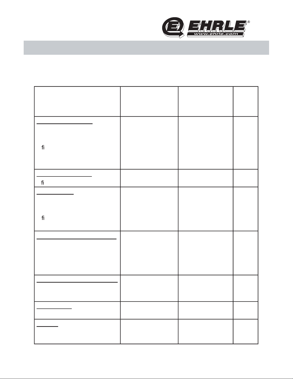
The table below shows the three categories in reference to work site.

Hochdruck-Reinigungs-Systeme High-Pressure-Systems
73
Category Type Work site (condition
Series HS
High Pressure Cleaner
oil red
HS 623, HS 840,
HS 1040,
HS 1140,
HSC 623,
HSC 1040
Electrical power (mains) is availa-
ble at the site. The exhaust can be
ued off with a chimney or direct
into the atmosphere.
Typical application for industry e.
g. car dealer ships, transport com-
panies and shippers, rail and bus
companies, farming, livestock and
arible, construction
companies, hire industry, highways
and transport, plant and machinery
maintenance re-brigades etc.
Series HSE
High Pressure Cleaner
electric heated
HSE 800,
HSE 1000
Electrical power (mains) is availa-
ble at the site. The exhaust from
an oil or gas red High Pressure
Cleaner is undesirable or prohi-
bited. Typical application for food
industry, supermarkets, abatoirs,
meat packing plants, sh industry,
hospitals, hotels, restaurants,
swimming pools, chemical
industry, airports etc.
Series HSG
High Pressure Cleaner
gas res
HSG 1240
Electrical power (mains) is availa-
ble at the site. The exhaust can be
ued off with a chimney or direct
into the atmosphere.
This High Pressure Cleaner may
be used in establishments, facto-
ries and workshops with modern
energy supplies such as natural
gas or L.P.G.
Hochdruck-Reinigungs-Systeme High-Pressure-Systems
74
1.2 Utilization
The High Pressure Cleaner series HS, HSE and HSG are in general used for
cleaning:
• Car dealer ships, transport companies and shippers, rail and bus companies,
• Fire brigades and automatic brush wash systems for pre-cleaning vehicles,
• Construction companies,
• Food industry, sanitary facilities,
• Chemical industry,
• Hospitals, large kitchens, swimming pools, catering.
Besides cleaning generally contaminated surfaces the EHRLE High Pressure
Cleaners shows its excellent features and optimum cleaning power when clea-
ning
• grease, oil or fat contaminated surfaces,
• tar contaminated surfaces,
• chemical contaminated surfaces etc,
The easy operateable and adjustable High Pressure Cleaner, e.g. setting the
water temperature, admixing and diluting the cleaning detergent, adjusting the
operating pressure and special nozzles ensure also optimum cleaning for dif -
cult tasks like tenacious encrusted contaminations.
1.3 Total view of stationary High Pressure Cleaner
The following gures show a general installation example for the stationary
High Pressure Cleaner oil red (series HS). Special accessories and options
allow customization to nearly every site. The series HS includes as follows:
• HS 623, HS 840, HS 1040, HS 1240.
For further information to installation of the series HSE and HSG
contact the manufacturer EHRLE.
NOTE
Hochdruck-Reinigungs-Systeme High-Pressure-Systems
75
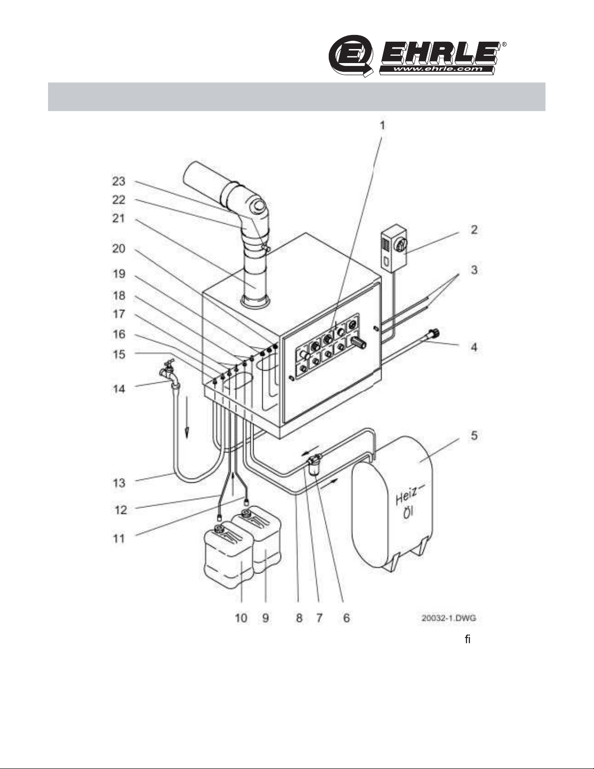
Figure 1 Stationary High Pressure Cleaner of series HS (oil red),
general example for installation (sheet 1 of 2)

Hochdruck-Reinigungs-Systeme High-Pressure-Systems
76
1 Control panel component of central unit
2 Main switch equipment of infrastructure
3 Cord remote control accessories
4 High pressure hose 1,5 m accessories
5 Fuel oil container equipment of infrastructure
6 Fuel supply device with lter accessories
7 Fuel oil suction pipe accessories
8 Fuel oil return pipe accessories
9 Detergent container I accessories
10 Detergent container II accessories
11 Detergent suction hose (I) accessories
12 Detergent suction hose (II) accessories
13 Water supply hose accessories
14 Shut off valve equipment of infrastructure
15 High pressure hose connection central unit interface
16 Water supply central unit interface
17 Detergent connection central unit interface
18 Connection fuel oil suction hose central unit interface
19 Wire joint cord remote control central unit interface
20 Wire joint electrical cord central unit interface
21 Adjustable chimney accessories
22 Chimney accessories
23 Adapter 120/150 accessories
with test hole
Hochdruck-Reinigungs-Systeme High-Pressure-Systems
77
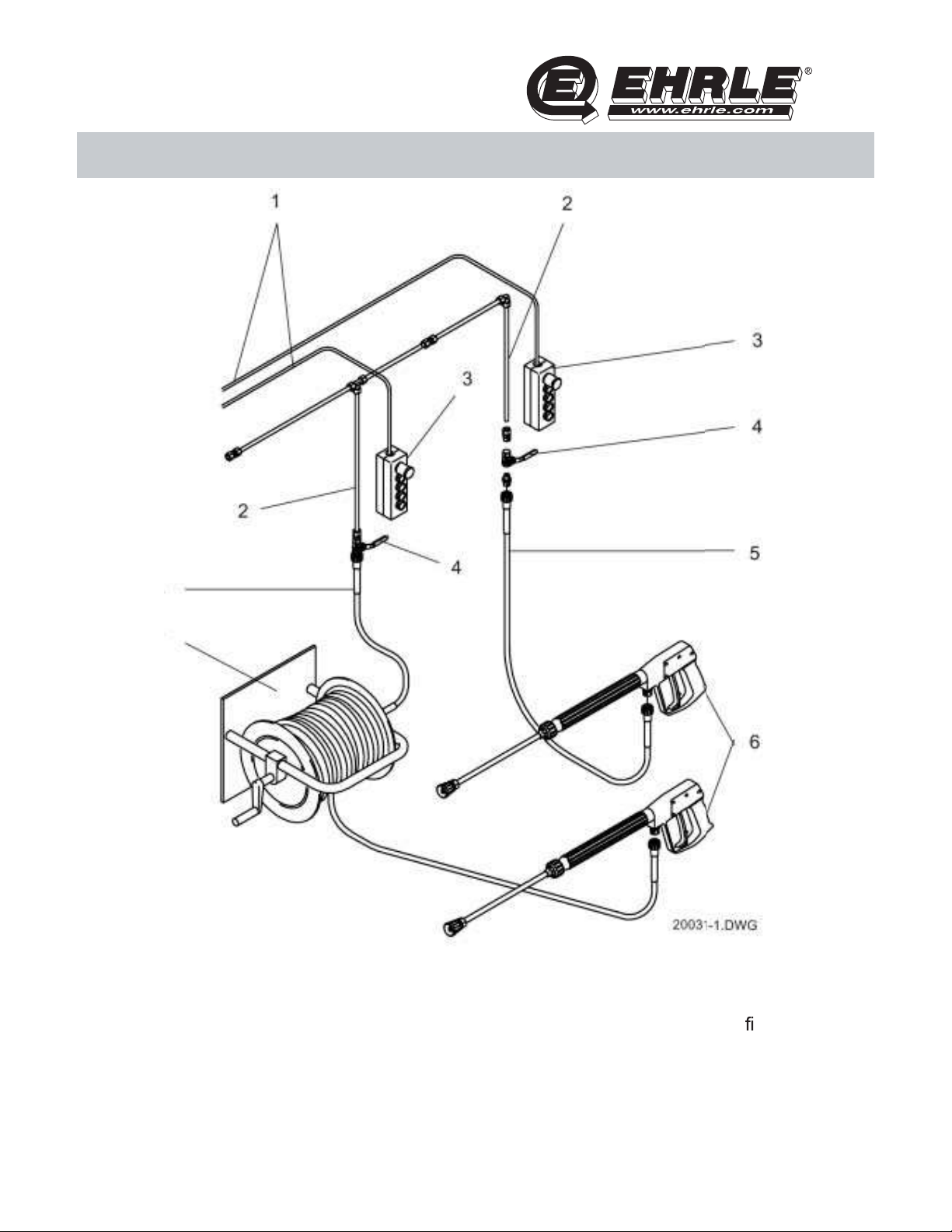
Figure 2 Stationary High Pressure Cleaner of series HS (oil red),
general example for installation (sheet 2 of 2)

Hochdruck-Reinigungs-Systeme High-Pressure-Systems
78
1 Cord remote control accessories
2 High pressure pipe accessories
3 Remote control accessories
4 High pressure block valve accessories
5 High pressure hose accessories
6 Trigger gun with spray lance accessories
7 Hose reel (wall xture) accessories
8 High pressure hose 1,5 m accessories
1.4 Technical data
1.4.1 Technical data for series HS 623, HS 840, HS 1040, HSC 623, HSC 1040
The table below shows the High Pressure Cleaner technical data for series
HS 623, HS 840, HS 1040, HSC 623 and HSC 1040.

Hochdruck-Reinigungs-Systeme High-Pressure-Systems
79
Designation HS 623
HSC 623 HS 840 HS 1040
HSC 1040 Unit
Operating pressure:
Standard nozzle
Hot water (with standard nozzle)
In nitely variable
Permissible operating pressure
Max. reaction force
B
2505
110
30 - 110
130
28
B
25045
150
30 - 150
170
37
B
2505
180
30 - 180
200
49
B
MEG
bar
bar
bar
N
Discharge capacity:
In nitely variable (water) 330 - 660 390 - 780 520 - 1000 l/h
Temperature:
Max. delivery temperature
Max. operating temperature
In nitely variable
Heating capacity (net)
T
30
98
30 - 98
46
T
30
98
30 - 98
50
T
30
98
30 - 98
63
T
°C
°C
°C
kW
Electrical input power (mains):
Voltage (frequency)
Consumption
Facility power outlet requires
fuse with
N
AC 230 ~ (50)
3,0
16 (inert)
1
N
3 x 400 ~ (50)
5,6
16 (inert)
1
N
3 x 400 ~ (50)
7,9
20 (inert)
1
N
V (Hz)
kW
A
Oil consumption:
Max. oil consumption
For temperature increase of 50 K
F
4,6
3,3
F
5,0
3,6
F
5,5
5,4
F
kg/h
kg/h
Capacities and suction quantity:
H. P. Pump motor oil W 15/40
Chemical suction quantity
F
0,5
0 - 10
F
0,5
0 - 10
F
0,6
0 - 10
F
l
l/h
Dimensions:
Length x Width x Height
A
830x650x690
A
830x650x690
A
830x650x690
A
mm
Weight:
Weight of machine without
accessories
G
130
G
135
G
140
G
kg

Hochdruck-Reinigungs-Systeme High-Pressure-Systems
80
1.4.2 Technical data for series HS 1240 and HSG 1240
The table below shows the High Pressure Cleaner technical data for series
HS 1240 and HSG 1240.
Designation HS 1240 HSG 1240 Unit
Operating pressure:
Standard nozzle
Hot water (with standard nozzle)
In nitely variable
Permissible operating pressure
Max. reaction force
B
2507
160
30 - 1600
180
43
B
2505
180
30 - 180
200
49
B
MEG
bar
bar
bar
N
Discharge capacity:
In nitely variable (water) 600 - 1200 520 - 1000 l/h
Temperature:
Max. delivery temperature
Max. operating temperature
In nitely variable
Heating capacity (net)
T
30
98
30 - 98
65
T
60
80
30 - 80
54
T
°C
°C
°C
kW
Electrical input power (mains):
Voltage (frequency)
Consumption
Facility power outlet requires
fuse with
N
3 x 400 ~ (50)
7,9
20 (inert)
1
N
3 x 400 ~ (50)
7,9
20 (inert)
1
N
V (Hz)
kW
A
Oil or gas consumption:
Max. fuel consumption
For temperature increase of 50 K
F
4,6 (oil)
3,3 (oil)
F
4,9 m³ gas H
4,9 m³ gas H
F
kg/h
kg/h
Capacities and suction quantity:
H. P. Pump motor oil W 15/40
Chemical suction quantity
F
0,5
0 - 10
F
0,6
0 - 10
F
l
l/h
Dimensions:
Length x Width x Height
A
830x650x690
A
830x650x690
A
mm
Weight:
Weight of machine without accessories
G
140
G
135
G
kg
Hochdruck-Reinigungs-Systeme High-Pressure-Systems
81
1.4.3 Technical data for series HSE 800 and HSE 1000
The table below shows the High Pressure Cleaner technical data for series
HSE 800 and HSE 1000.
Designation HSE 800 HSE 1000 Unit
Operating pressure:
Standard nozzle
Hot water (with standard nozzle)
In nitely variable
Permissible operating pressure
Max. reaction force
B
25045
120
30 - 120
130
28
B
2505
180
30 - 180
200
49
B
MEG
bar
bar
bar
N
Discharge capacity:
In nitely variable (water) 390 - 780 500 - 1000 l/h
Temperature:
Max. delivery temperature
Max. operating temperature
In nitely variable
Heating capacity (net)
T
30
70
30 - 70
18/24
T
30
70
30 - 70
24/30
T
°C
°C
°C
kW
Electrical input power (mains):
Voltage (frequency)
Consumption
Facility power outlet requires
fuse with
N
3 x 400 ~ (50)
23/32
35/50 (inert)
1
N
3 x 400 ~ (50)
32/38
50/63 (inert)
1
N
V (Hz)
kW
A
Capacities and suction quantity:
H. P. Pump motor oil W 15/40
Chemical suction quantity
F
0,5
0 - 10
F
0,5
0 - 10
F
l
l/h
Dimensions:
Length x Width x Height
A
830x650x690
A
830x650x690
A
mm
Weight:
Weight of machine without
accessories
G
120
G
125
G
kg

Hochdruck-Reinigungs-Systeme High-Pressure-Systems
82
1.5 General function of High Pressure Cleaner
1.5.1 General function of series HS and HSC
The water from the water system ows through the water inlet (01) to the oat
container (02), when the trigger gun (17) is activated (see gure 3). The low
water cut off (03) switches off the High Pressure Cleaner, when the oat con-
tainer (02) is empty.
The high pressure pump (05) absorbes the water from the oat container (02)
through the low pressure injector (04). The high pressure pump (05) pressuri-
zes the water to the adjusted operating pressure.
The pressure switch (07) monitors the operating pressure. It switches on the
fuel pump (26) for the oil burner (27) in the heat exchanger (14), when the
pressure exceeds 25 bar.
When the trigger gun (17) is activated, the water is pumped through the unloa-
der valve (08). This is an adjustable control element for reducing the operation
pressure.
After the non return valve (09), which is integrated in the unloader valve (08),
the pressure gauge (10) indicates the operating pressure. The pressure switch
(11) switches on the High Pressure Cleaner, when the trigger gun (17) is
activated and the pressure is under a threshold of 25 bar.
The safety valve (12) prevents an unallowed pressure increase. Then the
water will be turned outside by the safety valve drain.
Via the ow switch (13) the water is fed to the heat exchanger (14). The ow
switch (13) switches off the oil burner (27) in the heat exchanger (14), when
the water ow is too less. The thermostat (15) is used for setting the desired
water temperature.
Depending on the chemical metering valve (20) setting the cleaning detergent
may be admixed to the water from one of two external connected cleaning
detergent containers (18 or 19).
The chemical low pressure injector (04) causes a suction in the cleaning
detergent path, when the high pressure pump (05) is activated and the che-
mical metering valve (20) is opened. The resulting underpressure sucks the
cleaning detergent and admixes it through the low pressure injector (04) into
the water circuit. The chemical metering valve (20) provides also the cleaning
detergent dilution adjustment. Whithout underpressure, the non return valve
(21) sepearates the cleaning detergent circuit from the water circuit.
The fuel oil pump (26) conveys the fuel oil from the external installed fuel oil
container through the fuel oil lter (24) to the oil burner (27). The ame control
(23) switches off the High Pressure Cleaner, if failures occur.

Hochdruck-Reinigungs-Systeme High-Pressure-Systems
83
When exceeding the determined exhaust threshold, the maximum thermostat
(28) switches off the High Pressure Cleaner and locks it.
01 Water inlet 10 Pressure gauge 20 Chemical metering valve
02 Float container 11 Pressure switch 21 Non return valve
03 Low water cut off 12 Safety valve 22 Temperature monitoring
04 Chemical low pressure 13 Flow switch for pump
injector 14 Heat exchanger 23 Flame control
05 High pressure pump 15 Thermostat 24 Fuel oil lter
06 Pump motor 16 High pressure outlet 25 Burner motor
07 Pressure switch 17 Trigger gun 26 Fuel oil pump
08 Unloader valve 18 Chemical draw external 27 Oil burner
09 Non return valve 19 Chemical draw external 28 Max. thermostat (exhaust)
Figure 3 High Pressure Cleaner series HS, functional diagram
This manual suits for next models
15
Table of contents
Other EHRLE Pressure Washer manuals


