EHV Kanuk 3 User manual

Kanuk® 3 & 4 Classic/with hotplate
und Turbo 1 & 2
Manual
Brilliantly simple – simply brilliant.

EHV GmbH • Entwicklung | Herstellung | Vertrieb • Hauptstraße 131 • 01744 Dippoldiswalde
2
1. Construction manual
1.1 General requirements
1.2 Weight
1.3 General requirements
1.3.1 Construction manual/accessories
1.4 Combustion air supply
1.5 Couplers
1.6 Distance to combustible components and furniture/ Fire protection
1.7 Chimneys
2. Directions for use
2.1 Safe combustibles
2.2 Use of Kanuk® hot-air kilns
2.3 Buttery control valve
2.4 Combustion air regulation
2.5 Heating up
2.6 Chimney re
2.7 Procedures during incidents - safe decommissioning
2.8 Relling
2.9 Bed of ashes
2.10 Cleaning
3. Guarantee
3.1 Guarantee/Warranty
4. Kanuk® Turbo additional information
Thank you for choosing a Kanuk® hot-air kiln. We wish you lots of fun
trying out your new Kanuk®. Please read this manual carefully before
rst use. It contains important notes and information on installation,
operation, and safe use.
1. Construction manual
Please take into account that combustion installations may only be put into ser-
vice after a district master chimneysweeper has veried functionality and safety
of the exhaust system (chimney) and the heating appliance.This also applies to
the case of changes.
TABLE OF CONTENTS
3
4
4
4
5
5
6
6
8
8
8
9
9
10
10
10
11
11
11
12

EHV GmbH • Entwicklung | Herstellung | Vertrieb • Hauptstraße 131 • 01744 Dippoldiswalde 3
STRUCTURE AND COMPONENTS OF THE KANUK®
Kanuk®Classic Kanuk®with hotplate Kanuk®Turbo
4
8
7
1
2
3
6
5
1.1. General requirements
Structure and components of the Kanuk®
Kiln shell 1
Door with special Schott Robax® glass 2
Door locking mechanism 3
Gas ue pipe 4
Ash catch plate 5
Primary air regulation 6
Supply air controller for secondary air regulation 7
Secondary air regulation 8
4
8
2
3
67
5
11
2
3
4
56
EHV GmbH • Entwicklung | Herstellung | Vertrieb • Hauptstraße 131 • 01744 Dippoldiswalde
4
CONSTRUCTION MANUAL
1.3. General requirements
Please adhere to the respective prescriptions governed by public law when
installing your Kanuk®, especially those set by the state building code and the
corresponding ring directives.
1.3.1 Construction manual / accessories
Ash catch plate
Remove the ash catch plate from its
packaging and clip it into the bolt underneath
the door from the top.
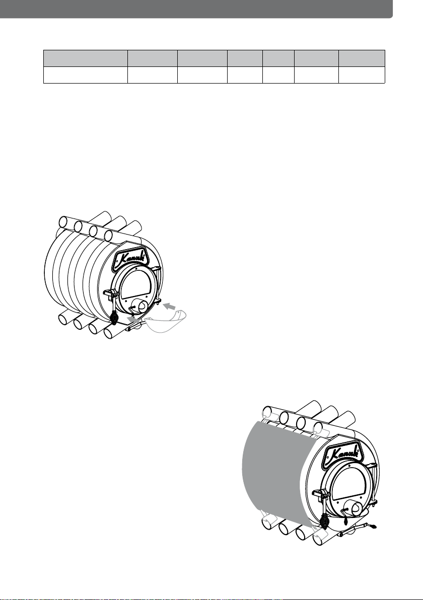
Kiln shell of the Kanuk® Classic
Step I
Push the hangers at the top and bottom
into the rst and last radiation tube. The
side panels will be clipped into the bottom
hangers.
Step II
Fix the side panels with the accompanying
screws at the top hangers.
Kanuk® model 3 Classic 4 Classic 3 HP* 4 HP Turbo 1 Turbo 2
Weight in kg 145 175 145 175 165 210
* HP = with hotplate
1.2. Weight

EHV GmbH • Entwicklung | Herstellung | Vertrieb • Hauptstraße 131 • 01744 Dippoldiswalde 5
CONSTRUCTION MANUAL
Kiln shell of the Kanuk® with hotplate
Step I
Push the hangers at the top and bottom
into the rst and last radiation tube.
The side panels will be clipped into the
bottom hangers.
Step II
Fix the side panels with the accompanying
screws at the top hangers.
Self-closing door layout I
Remove the circlip of the door-xing bolt. Now pull the bolt
to the top and push it into the torsion spring. The medium
hanger of the spring will be xed on the doorframe. The ends
of the springs are to be xed behind the door suspension.
Now return the bolt to the primary position and x it with the
circlip. Please make sure to x the door additionally during
the entire process.
1.4. 1.4. Combustion air supply
The combustion air supply is sucient for Kanuk® hot-air kilns up to a nominal
heating capacity of 27 kW, provided there is at least one door or
window to be opened. Furthermore, the room needs a cross-section of
at least 150 cm². The room must not fall below 4 m³ per kW of nominal
heating capacity.
EHV GmbH • Entwicklung | Herstellung | Vertrieb • Hauptstraße 131 • 01744 Dippoldiswalde
6
1.5. Couplers
The coupler between the heat system and the exhaust system (chimney) ought
to be as short as possible, straight and needs to be installed in rising position.
You may need to caulk the links. For cleaning the couplers, there ought to be at
least one opening left free.The material density must not fall below 2 mm.
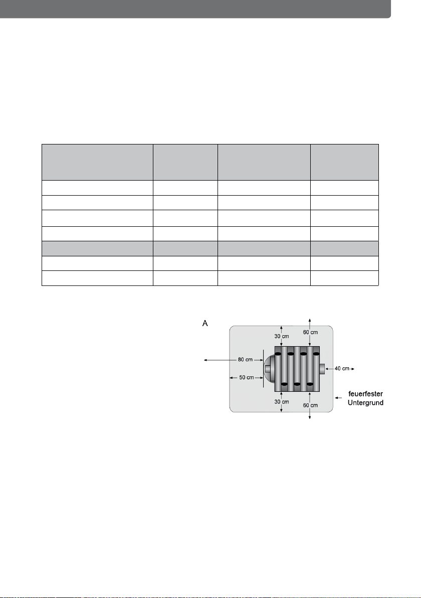
1.6. Fire protection – distance to combustible components and furniture
forward
from the side
with side plate /
without side plate
back
Kanuk® 3 Classic 80 cm 50 cm / 80 cm 40 cm
Kanuk® 4 Classic 80 cm 55 cm / 90 cm 40 cm
Kanuk® 3 with hotplate 80 cm 50 cm / 80 cm 40 cm
Kanuk® 4 with hotplate 80 cm 55 cm / 90 cm 40 cm
forward from the side back
Kanuk® Turbo 1 80 cm 80 cm 40 cm
Kanuk® Turbo 2 80 cm 90 cm 40 cm
CONSTRUCTION MANUAL
Flammable oor coverings
have to be protected by re-
resistant material.
In addition the material needs
to be placed also at least 50
cm in front of the stove and
30 cm next to it.
1.7. Chimneys
Kanuk® hot-air kilns don’t require a chimney of their own if the door
spring was tted for layout 1.The combustion measurements were
carried out according to the norm DIN 13384 parts 1, 2 and 3 with the value
triplet given in table 1.

EHV GmbH • Entwicklung | Herstellung | Vertrieb • Hauptstraße 131 • 01744 Dippoldiswalde 7
Table 1: Value triplet for measurements of chimneys according to DIN
13384 parts 1, 2 and 3:
Kanuk® model 3 Classic 4 Classic 3 HP* 4 HP Turbo 1 Turbo 2
Nominal heat output in kW 22 27 22 27 20 30
Eciency in % 83 82,4 83 82,4 83,7 82,4
Emission temperature in °C 238 238 238 238 238 238
CO2in % 9,89 9,89 9,89 9,89 9,89 9,89
CO in mg/m³ 1094 1196 1094 1196 992 1196
Exhaust ow rate in g/s 19,5 24,8 19,5 24,8 14,2 24,8
Dust in mg/m³ 29 36 29 36 22 36
Minimal chimney draft in Pa 12 12 12 12 12 12
* HP = with hotplate
Table 2: Combustion chamber performance data:
Kanuk® model 3 Classic 4 Classic 3 HP** 4 HP Turbo 1 Turbo 2
fuel consumption in kg/h 7 8,6 7 8,6 6,9 8,9
maximum log length in cm 65 80 65 80 65 80
maximum heatable volume
in m³ *
700 1000 700 1000 650 1000
maximum quantity of com-
bustible in kg
7 8,6 7 8,6 6,9 8,9
* depending on building structure, insulation, etc.
** HP = with hotplate
CONSTRUCTION MANUAL
Note: We can only guarantee the operational safety and the nominal heat
outputs of our Kanuk® hot-air kilns as long as the combustion measurements
of the chimneys were carried out according to the norm DIN 13384 part 1, 2
and 3 and was attested by a district master chimneysweeper.

EHV GmbH • Entwicklung | Herstellung | Vertrieb • Hauptstraße 131 • 01744 Dippoldiswalde
8
2. Directions of use
2.1. Safe combustibles
Only air-dried, natural logs of wood measuring between 25-80 cm in
length and 35 cm in diameter with less than 20% water content may be
used as combustibles. In case you use wood remainders, make sure it was
stored in a dry place for at least two years before using it as rewood.
Never use more than the given amount in table 2 at a time to prevent
overheating of the Kanuk® hot-air kiln. Don’t use treated or plastic-coated
wood, chip trays, sawdust, coal, coke, or similar combustibles!
2.2. Use of Kanuk®
Kanuk® hot-air kilns may only be used with combustion chamber door
closed. All Kanuk® hot-air kilns can be tted with a self-closing door
mechanism (layout 1).
2.3. Buttery control valve
Remember to open the buttery control valve in
the exhaust gas stub when using the Kanuk®
hotair kiln (position 0). The hand knob must be
pointing in the direction of the exhaust gas stub.
In case of a high draught of the chimney (see ta-
ble 1, feed pressure), the control valve in the ex-
haust gas stub can be partially closed (position
Z).
Note: Overheating and/or improper combustibles can result in
damage of the combustion chamber! See table 2: maximal combustible
amounts (given in kilograms per hour).
DIRECTIONS OF USE

EHV GmbH • Entwicklung | Herstellung | Vertrieb • Hauptstraße 131 • 01744 Dippoldiswalde 9
2.4. Combustion air regulation
Kanuk® hot-air kilns are tted with primary
(image B) and secondary (image A) air vents
for combustion air supply. During heating up
and use with nominal heat output, the primary
and secondary air vent in the rear wall must be
opened. The primary air vent (imageB) is prima-
rily meant for pane ventilation and ought to be
closed partially or fully only for incandescence.
By closing the secondary air vent in
the rear wall, the combustion air ven-
tilation will be choked. This can result in higher emission rate.
The secondary air vents cannot be closed fully for safety reasons.
2.5. Heating up
Fully open the control valve in the exhaust gas stub, the primary air vent in the
combustion chamber door, and the secondary air vent in the rear wall. For hea-
ting up, stack the rewood in a pyramid over screwed paper and cover it in thin
logs of wood.Then start the re. After heating up, ll up the Kanuk® hot-air kiln
with logs according to chapter 2.1.
Before the rst heating-up, make sure to check the correct installation of the vie-
wing window of the Kanuk® hot-air kiln. The screws for the hanger on the front
side of the combustion chamber door must be tightened to the degree that the
door remains movable (hand-tight).
Note: Kanuk® hot-air kilns are coated in high quality heat-resistant
paint. During the rst phase of heating up, the burn-in of the paint may
result in slight smoke development and odor nuisance. Make sure to
keep your windows and doors open when heating up the kiln for the
rst time.
DIRECTIONS OF USE
Note: For the protection of the stove you should pay attention to the
fact, that the stove is loaded moderately with rewood, so that the steel
can distend steadily. Because of the amazing temperature dierences
between the ambiant temperature and the temperature within the sto-
ve, there may be crackling noises withing the Kanuk®.

10
DIRECTIONS OF USE
2.6. Information in case of a chimney re
If you use the wrong combustible or if the combustible is still too wet, there is
the possibility of deposits in the chimney, which may cause a chimney re. The
air supply at the stove has to be closed immediately and of course you have to
contact the re brigade and your chimney sweeper as well. After the re is done,
the chimney needs to be checked by a specialist, to make sure that there are no
damages or leakinesses.
2.7. Procedure in case of incidences – safe shutdown
In some rare cases there is the possibility that there is no draught in the chimney
and that even a pilot re will not help. If that‘s the problem, you have to contact
a chimney sweeper, in no case try to light a bigger re. If there is smoke escaping
from the stove, of course the chimney sweeper has to be informed, too. Open
every window immediately, to make sure that there is enough fresh air available.
2.8. Relling
Open the primary air vent in the combustion chamber door and the se-
condary air vent in the rear wall and set the control valve in the exhaust
gas stub to position A. Then open the combustion chamber door and ll
with wooden logs until reaching the rear wall. Make sure to leave enough
space underneath the logs, as that will prevent the re from being hoked.
When close the combustion chamber door. Once the logs are well burnt,
you can consider curtailing the primary and secondary air vent to facilitate
a more regular burn-o. Make sure to leave the primary air vent open at all
times for the pane ventilation to function without interference.
2.9. Bed of ashes
Remember to leave a 5-10 cm layer of ashes on the ground of the combustion
chamber. The bed of ashes will protect the ground of the kiln from blowing.
Remove only excess ashes with a shovel every now and then. You can obtain
the required accessories from your Kanuk® co-contractor.

EHV GmbH • Entwicklung | Herstellung | Vertrieb • Hauptstraße 131 • 01744 Dippoldiswalde 11
DIRECTIONS OF USE
2.10. Cleaning
The gas leading parts of the Kanuk® hot-air kilns (bae plate, buttery
valve, etc.) and the connecting pieces need to be cleaned in case of de-
lement. Carry out a cleaning in all cases once during and after the heating
period. The sealing cord of the combustion chamber door needs to be re-
placed in case of damage.
3. Guarantee
3.1. Guarantee / Warranty
End consumers get a two-year guarantee. In case of commercial use, the gu-
arantee period is extended by 12 months. Viewing panes and ceramic sealing
cords are generally not included in the guarantee. In case of damage, please
contact your Kanuk® co-contractor in rst instance. Photos of the blemished
element and the location of installation as well as the exhaust system are requi-
red in general for handling cases of damage. Furthermore, please submit the
production number and a detailed description of damage. Ask your co-contrac-
tor for the required form sheet. Only original or spare parts accredited by the
manufacturer may be used. Wrong use and inobservance of this manual will
abrogate the warranty claim.

EHV GmbH • Entwicklung | Herstellung | Vertrieb • Hauptstraße 131 • 01744 Dippoldiswalde
12
KANUK® TURBO ADDITIONAL INFORMATION
4. Kanuk® Turbo additional information
This supplement provides additional information concerning the wood-
burning stoves Kanuk® Turbo. Please read these information carefully be-
fore using the Kanuk® Turbo.
Combustion air supply
For the Kanuk® Turbo wood stoves with a heat output up to 30 kW the
combustion air intake is sucient:
• when the location has at least one door to the outside
• or a window that can be opened (cross section >200 cm²)
The location should have a cubage of not less than 4 m² per kW heat out-
put.
Chimneys
Kanuk® Turbo wood-burning stoves don‘t need an own chimney. The re
rating results from DIN 13384 part 1, 2 and 3 with the triplet shown in
table 1.
Kanuk® Turbo wood-burning stoves don‘t need an own chimney. The re
rating results from DIN 13384 part 1, 2 and 3 with the triplet shown in
table 1.
Kanuk® model Turbo 1 Turbo 2
Nominal heat output in kW 20 30
E ciency in % 83,7 82,4
Abgastemperatur in °C 238 238
CO2in % 9,89 9,89
CO in mg/m³ 992 1196
Exhaust ow rate in g/s 14,2 24,8
Dust in mg/m³ 22 36
Minimal chimney draft in Pa 12 12
Note: We only guarantee operating safety and heat outputs from
our Kanuk® Turbo wood stoves, when the adequate re rating of the
chimney is proven with a calculation via DIN 13384 part 1, 2 and 3 and
when it is certicated by a chimney sweep.

EHV GmbH • Entwicklung | Herstellung | Vertrieb • Hauptstraße 131 • 01744 Dippoldiswalde 13
KANUK® TURBO ADDITIONAL INFORMATION
Table 2: Combustion chamber - performance characteristics
Kanuk® model Turbo 1 Turbo 2
fuel consumption in kg/h 5,7 8,6
maximum log length in cm 65 80
maximum heatable volume in m³ * 650 1000
* depending on building structure, insulation, etc.
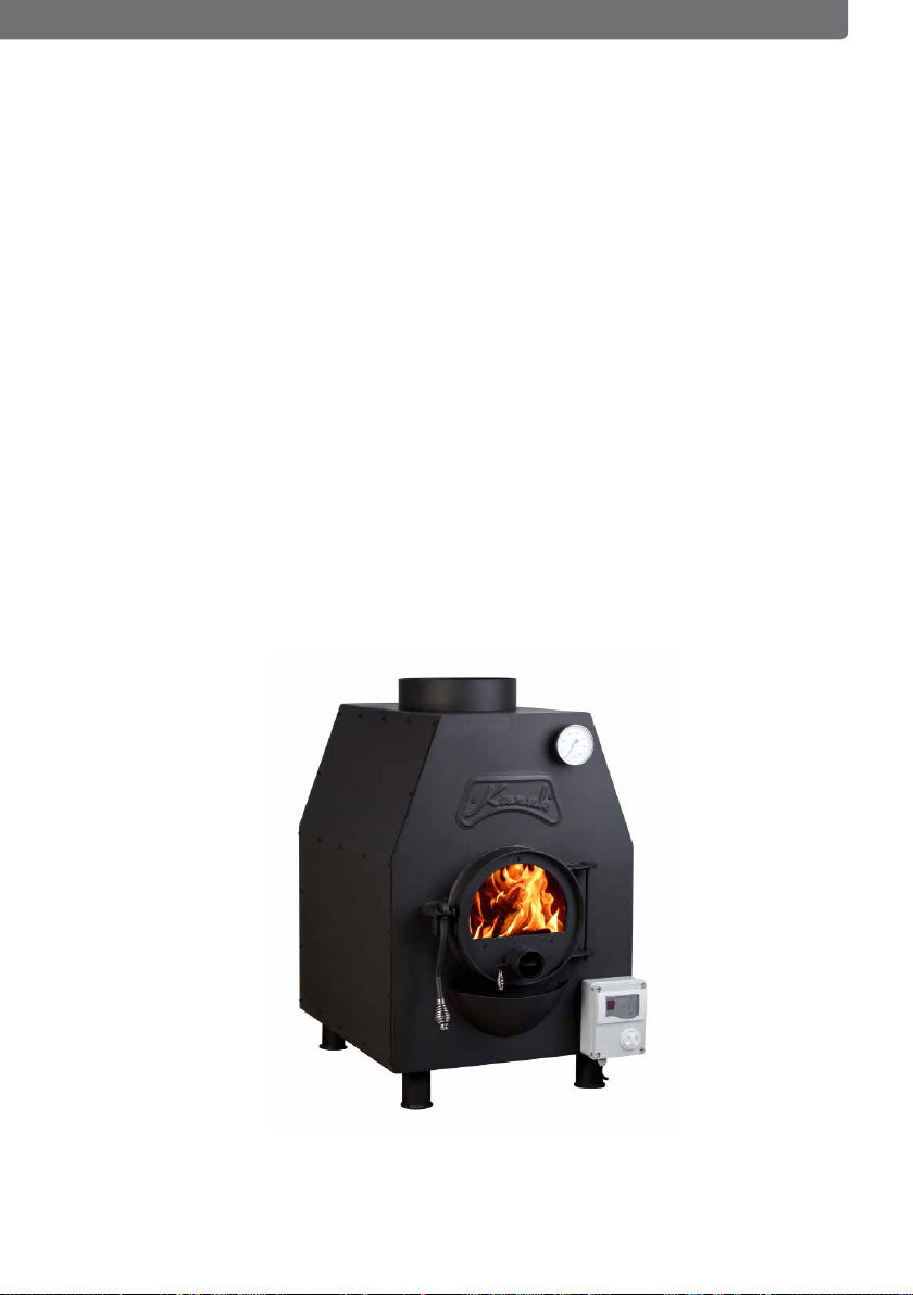
Operation instruction for Kanuk® Turbo wood-burning stoves
Ventilator
The ventilator is installed at the back of the Kanuk® Turbo and it turns bet-
ween 1600 and 2000 m³ an hour.
The ventilator‘s power can be regulated stageless and it is possbile to con-
trol it additionnaly with the thermostat at the front‘s right side of the sto-
ve. The temperature indicator is xed at the front‘s upper part. It meters
the temperature between covering and combustion chamber.
temperature indicator control
Ventilator and control are supplied with 230 V via a normal power outlet.
Note: It is generally forbidden to put objects into the opening of the air
inlet. This can inuence the operating or damage the ventilator com-
pletely.
On/O
speed governor
ventilator
thermostat
EHV GmbH • Entwicklung | Herstellung | Vertrieb • Hauptstraße 131 • 01744 Dippoldiswalde
14
Connecting pieces - air ducts
The wood-burning stoves Kanuk® Turbo 1 and 2 oer connecting pieces
for forwarding/distribution of the warm air into air ducts above the stove‘s
dome. For the connection it is possible to use a normal aerating pipe (fol-
ded spiral-seam pipe). There is also the possibility to use pipe bends, T-
pieces, Y-pieces or similar connection pieces to forward the warm air.
Connection diameter:
Kanuk® Turbo 1 - 315 mm diameter
Kanuk® Turbo 1 - 315 mm diameter
The xation is made with self-tapping screws directly into the connecting
piece. Additionally you may use heat-resistant sealant.Warranty and eci-
ency of the Kanuk® Turbo wood-burning stoves can only be guaranteed
under consideration of the operating instruction.
KANUK® TURBO ADDITIONAL INFORMATION

EHV GmbH • Entwicklung | Herstellung | Vertrieb • Hauptstraße 131 • 01744 Dippoldiswalde 15

EHV GmbH • Entwicklung | Herstellung | Vertrieb • Hauptstraße 131 • 01744 Dippoldiswalde
16 EHV GmbH • Entwicklung | Herstellung | Vertrieb • Hauptstraße 131 • 01744 Dippoldiswalde
EHV GmbH
Hauptstraße 131
01744 Dippoldiswalde
This manual suits for next models
6
Table of contents
Other EHV Stove manuals

Popular Stove manuals by other brands


Vermont Castings
Vermont Castings Resolute Installation planning guide

Stanley
Stanley ARGON F650 INSTALLATION, SERVICING AND USER OPERATING INSTRUCTIONS

EIRECO
EIRECO 740 Designed and manufactured in ireland

ACR Electronics
ACR Electronics Tenbury T5500 instruction manual

klover
klover BI-FIRE manual

Vermont Castings
Vermont Castings Jefferson 2822 Homeowner's installation and operating manual


