Eicon EiconCard P92 User manual
EiconCard P92
for PCI-Compatible Bus
Installation Guide
203-086-01
203086-1.FM5 Page 1 Friday, February 28, 1997 10:35 AM
First Edition (February 1997)
EiconCard P92 and EiconCard are trademarks of Eicon Technology Corporation.
IBM, IBM Personal Computer, PC AT, PC XT, Personal System/2, and PS/2, are
registered trademarks of International Business Machines Corporation.
Changes are periodically made to the information herein; these changes will be
incorporated into new editions of the publication. Eicon Technology may make
improvements and/or changes in the products and/or programs described in this
publication at any time.
A Product Comment Form is provided at the back of this publication. If the form has
been removed, address your comments to the attention of Corporate Publications at
Eicon Technologymayuseordistributewhateverinformationyousupplyin anyway
it believes appropriate without incurring any obligations to you.
Copyright © 1997 Eicon Technology Corporation. All rights reserved, including
those to reproduce this publication or parts thereof in any form without permission
in writing from Eicon Technology Corporation.
EICON TECHNOLOGY CORPORATION
9800 Cavendish Blvd.
Montreal, Quebec
Canada, H4M 2V9 EiconCard P92
Model Number: 800-298
FCC ID: E3S5NN 800-298
MADE IN CANADA
This device complies with FCC Rules, Part 15. Operation is subject
to the following two conditions:
1) This device may not cause harmful interference, and
2) This device must accept any interference that may be received,
including interference that may cause undesired operation.
203086-1.FM5 Page 2 Friday, February 28, 1997 10:35 AM

Table of Contents
Introduction ........................................................................... 5
Installing the EiconCard P92 ................................................ 6
Selecting an Interface ............................................................ 7
Connection Status Indicators ................................................ 8
Interface Specifications ......................................................... 9
The V.24 Interface .............................................................................. 10
The V.35 Interface .............................................................................. 12
The EIA-530 Interface ....................................................................... 14
The V.36/RS-449 Interface ................................................................. 16
The X.21 Interface .............................................................................. 18
Back-to-Back Connections ................................................................. 20
Cable Construction Information ......................................................... 21
Technical Specifications ..................................................... 22
International Regulatory Information ................................. 23
Limited Warranty ................................................................ 27
203086-1.FM5 Page 3 Friday, February 28, 1997 10:35 AM

4 EiconCard P92 Installation Guide
203086-1.FM5 Page 4 Friday, February 28, 1997 10:35 AM

EiconCard P92 Installation Guide 5
Introduction
This guide describes how to install the EiconCard P92 card in any
computer with a PCI-compatible bus.
The EiconCard P92 allows stand-alone PCs or multiple users on a
Local Area Network (LAN) to make very high speed connections to
a Wide Area Network (WAN). These connections are typically made
through the EiconCard P92 to external communications equipment
(including CSUs, DSUs, and synchronous and asynchronous
modems) to provide access to WAN lines. Direct connections to a
host computer or to another EiconCard are also supported.
Hardware Features
The EiconCard P92 features a 10MHz Hitachi 64570 controller and
512 KB of on-board RAM. It has two independent Very High-Speed
Interface (VHSI) ports, supporting full duplex communications over
a V.24, V.35, EIA-530, V.36/RS-449, or X.21 interface at speeds of
up to 2 Mbps per port, depending on the type of interface selected.
Ease of Use
No interface selection is required beyond connecting the appropriate
cable to the EiconCard P92. The intelligent controller on the card
detects which interfaces the cable supports and automatically
configures that port accordingly.
203086-1.FM5 Page 5 Friday, February 28, 1997 10:35 AM
6 EiconCard P92 Installation Guide
Installing the EiconCard P92
The steps below describe how to install the EiconCard P92.
1 Prepare the PC
Turn off the PC and disconnect its power cable. Remove the cover of
the PC according to the instructions that came with it.
2 Install the EiconCard P92
Insert the EiconCard P92 in any available PCI port. Secure the
adapter to the chassis of the PC using the bracket-retaining screw.
Reinstall the cover of the PC and reconnect the power cable.
3 Test the EiconCard P92
The application software that you purchased with the EiconCard P92
contains a test program to verify the card’s integrity. Consult the
documentation supplied with this software for details.
4 Configure the EiconCard P92
BeforeyoucanusetheEiconCard P92, you must configureittowork
with your communications software. The documentation which came
with this software contains complete instructions
on how to configure the card. During
configuration, note the following:
• The ports are numbered Port 1 and Port 2 as
indicated in Figure 1.
• The LEDs indicate connection and
configuration status. For a description of
connection status indications, see page 8.
For a description of how the LEDs are used
during configuration, consult the
documentation which came with your
networking software.
Figure 1. End Bracket
Port 1
LED 1
Port 2
LED 2
203086-1.FM5 Page 6 Friday, February 28, 1997 10:35 AM
EiconCard P92 Installation Guide 7
Selecting an Interface
The EiconCard P92 can connect as a DTE to devices such as Data
Service Units (DSUs) which support one of the following interfaces:
V.24, V.35, EIA-530, V.36/RS-449, or X.21. It can also connect
directly to a host computer, or back-to-back to another EiconCard.
Each VHSI port is configured independently.
Table 1 lists the most common connections for each interface, and
gives the part number of the required Eicon Technology cable. For
information on making your own cables, see “Interface
Specifications,” on page 9.
Table 1. Standard Interface Cables
To use an interface, simply install the appropriate cable. The
EiconCard P92 recognizes the cable and automatically prepares the
port for that interface.
Consult the documentation which came with your networking
software for more information about port configuration.
Interface Connection Part #
V.24 to V.24 DCE 300-077
to V.24 DTE 300-078
V.35 to V.35 DCE 300-076
to V.35 DCE (France) 300-083
EIA-530 to EIA-530 DCE 300-080
V.36/RS-449 to V.36/RS-449 DCE 300-079
X.21 to X.21 DCE 300-081
Direct to VHSI port on another EiconCard P92 or
compatible Eicon Technology EiconCard 300-075
203086-1.FM5 Page 7 Friday, February 28, 1997 10:35 AM

8 EiconCard P92 Installation Guide
Connection Status Indicators
The green LED adjacent to each port on the EiconCard P92—see
Figure 1 on page 6—provides a convenient indication of the status of
the connection on that port. The LED indicates the status as follows:
Table 2. Explanation of LED States
LED State Connection Status Remedy
Off The port is not loaded (the configuration
file describing protocol and interface
parameters has not been read by the
device driver on the PC).
Consult your networking
software for instructions on
howtoloadaconfigurationfile
and how to start a connection.
Rapid Flash
(stays on for
1/2 second)
The connection has not been established.
Either the port is loading OR there is no
response from the destination device
OR the EiconCard P92 is waiting for a
VHSI cable to be connected to the port.
Verify that the cable is
properlyconnected to theport.
If the light continues flashing
after a few minutes, verify that
the destination device is active.
Slow Flash
(stays on for
1 second)
The connection was interrupted
unexpectedly. The cable was unplugged
or damaged while a connection was
active.
Reconnect the cable.
On The port is active and the connection
is good.
203086-1.FM5 Page 8 Friday, February 28, 1997 10:35 AM
EiconCard P92 Installation Guide 9
Interface Specifications
The standards compliant with each interface supported on the VHSI
ports are listed in Table 3. The rest of this section describes the
allocation of pins used to implement the electrical and signalling
requirements of each interface. A wiring diagram is also provided, to
show the correspondence of the interface pinout to the VHSI port.
Table 3. Interface Compatibility
Interface Standard Compatibility
V.24 CCITT V.24 Signalling
CCITT V.28 Electrical
CCITT X.21bis Electrical and signalling
EIA RS-232-C Electrical and signalling
ISO 2110 Connector type for the DCE side of a V.24
VHSI Modem Cable
V.35 CCITT V.28 Some signals for electrical
CCITT V.35 Some signals for electrical and signalling
ISO 2593 Connector type for the DCE side of a V.35
VHSI Modem Cable
EIA-530 RS-422 Electrical
RS-423 Electrical
ISO 2110 Connector type for the DCE side of a EIA-
530 VHSI Modem Cable
V.36/RS-449 CCITT V.10 Electrical
CCITT V.11 Electrical
RS-422 Electrical
RS-423 Electrical
ISO 4902 Connector type for the DCE side of a V.36/
RS-449 VHSI Modem Cable
X.21 CCITT X.21 Signalling
CCITT V.11 Electrical
CCITT X.27 Electrical
EIA RS-422-A Electrical
ISO 4903 Connector type for the DCE side of an X.21
VHSI Modem Cable
203086-1.FM5 Page 9 Friday, February 28, 1997 10:35 AM
10 EiconCard P92 Installation Guide
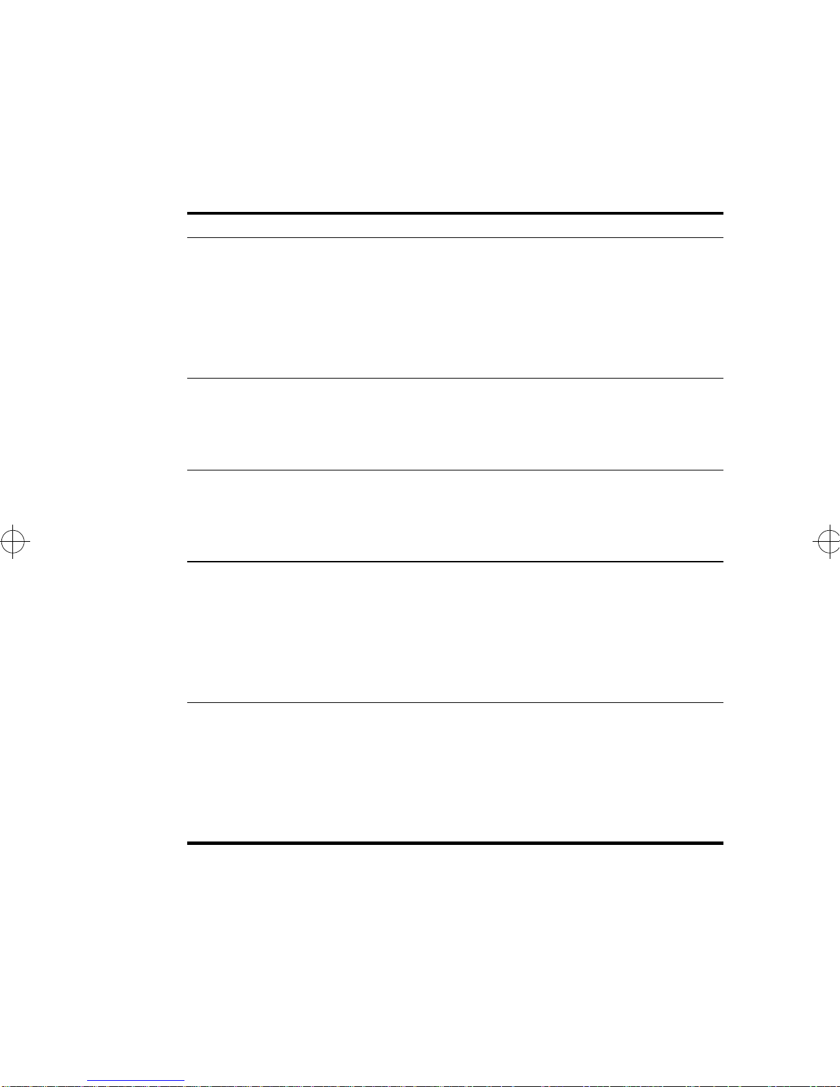
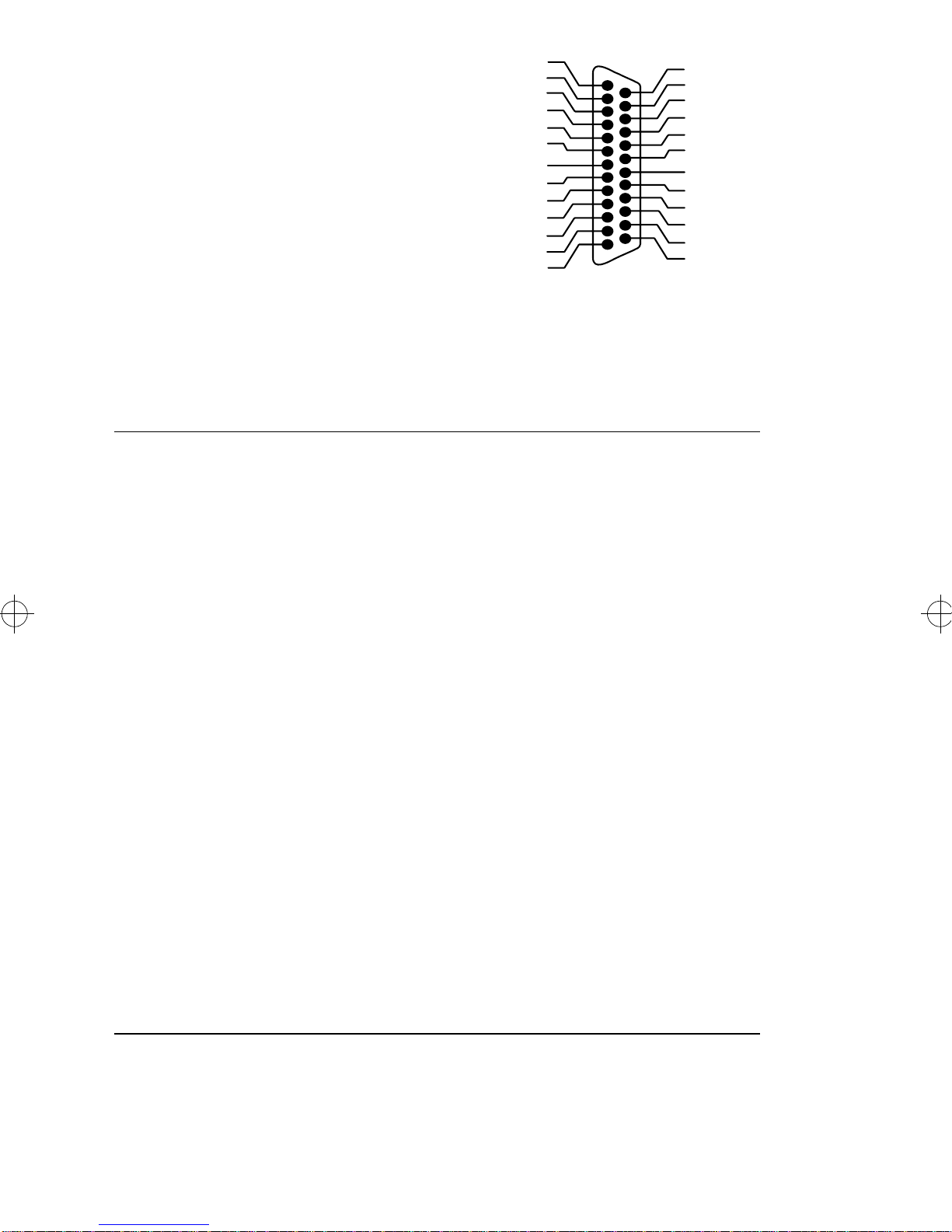
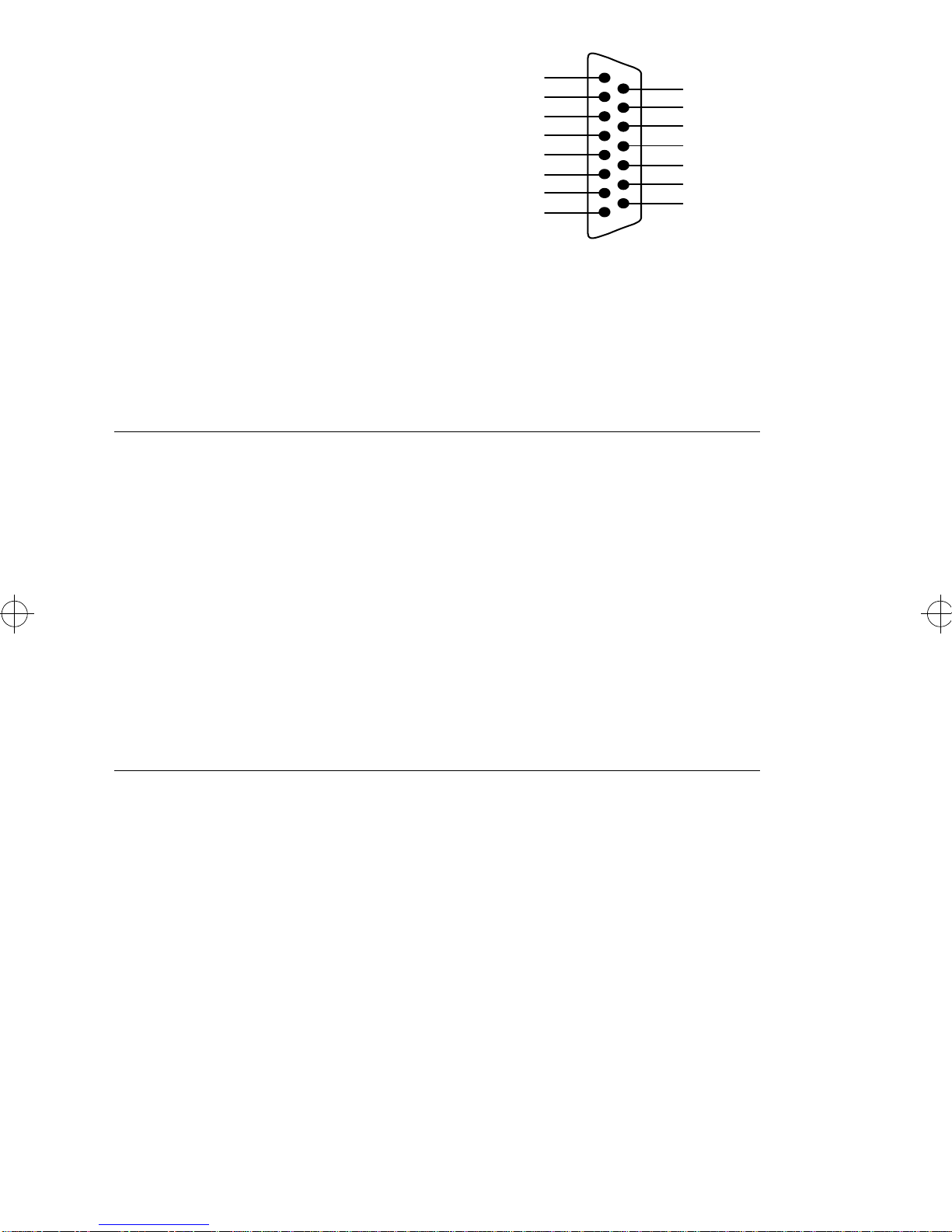
The V.24 Interface
A pin-out diagram for the V.24
interface is shown in Figure 2. The
signal definitions and names are
listed in Table 4.
Figure 2. V.24 Interface
PGND
RXD
RTS
1
RI
DCD
SGND
TXD
TCLK
CTS
DSR DTR
DTECLK
TEST
RLB
TI
25
RCLK
14
13
Table 4. V.24 Interface Signals
Pin #
Signal Name Direction CCITT #
1 PGND Protective Ground Common 101
2 TXD Transmit Data Output 103
3 RXD Receive Data Input 104
4 RTS Request to Send Output 105
5 CTS Clear to Send Input 106
6 DSR Data Set Ready Input 107
7 SGND Signal Ground Common 102
8 DCD Data Carrier Detect Input 109
15 TCLK Transmit Clock (DCE) Input 114
17 RCLK Receive Clock Input 115
18 TEST Local Loopback Activation Output 141
20 DTR Data Terminal Ready Output 108
21 RLB Remote Loopback Output 140
22 RI Ring Indicator Input 125
24 DTECLK Transmit Clock (DTE) Output 113
25 TI Test Indicator Input 142
203086-1.FM5 Page 10 Friday, February 28, 1997 10:35 AM
EiconCard P92 Installation Guide 11
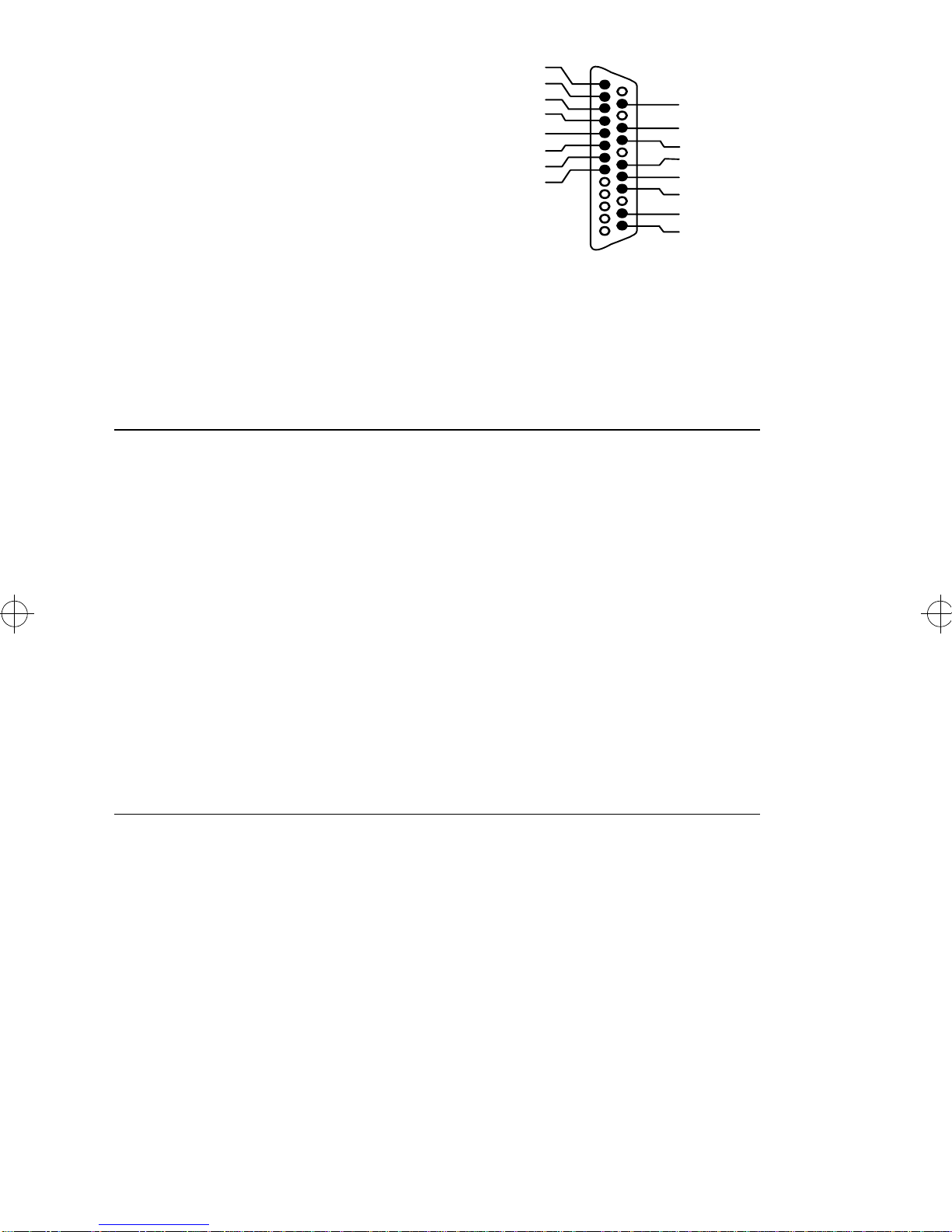
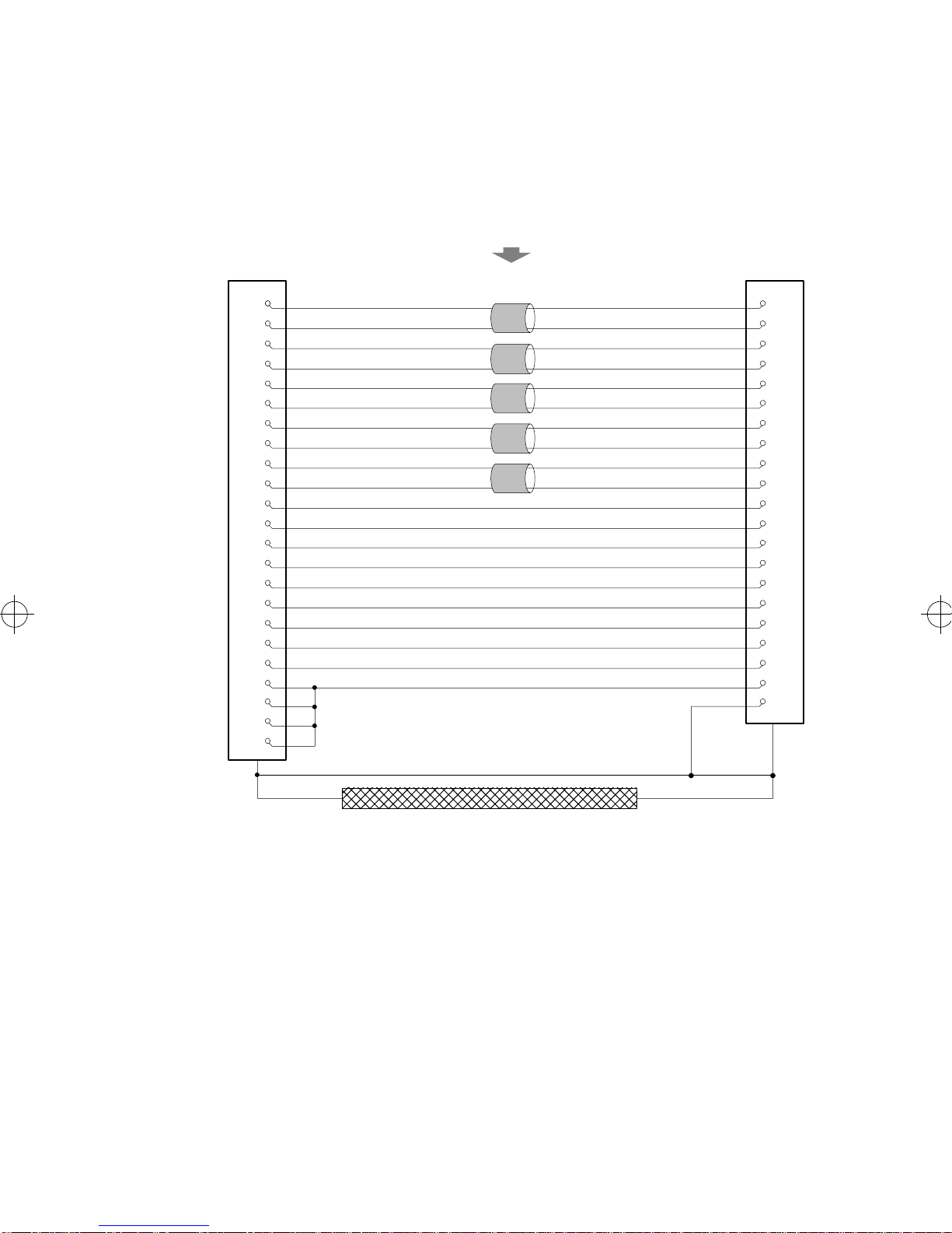
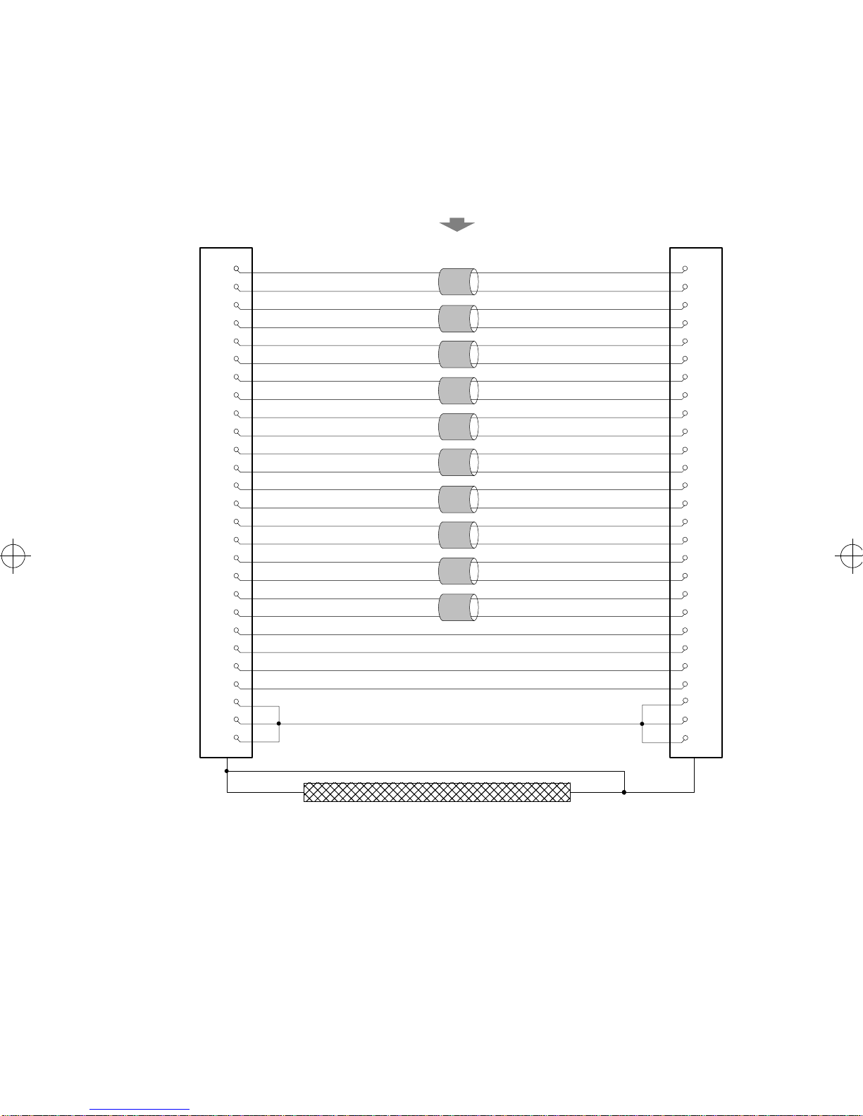
VHSI—V.24 Connections
The wiring diagram below shows the connections required to
construct a VHSI—V.24 cable. For the additional information
required to construct your own cables, see “Cable Construction
Information,” on page 21.
Figure 3. VHSI—V.24 Connections
7
VHSI
V.24
23
35
DRAIN WIRE
1
BRAID
724
9 5
11 6
12 2
13 8
15 15
16 17
18 22
20 3
21 18
25 4
30 20
33 21
34 25
1
2
3
19
5
17
6
10
23
35
24
28
8
14
26
32
203086-1.FM5 Page 11 Friday, February 28, 1997 10:35 AM
12 EiconCard P92 Installation Guide
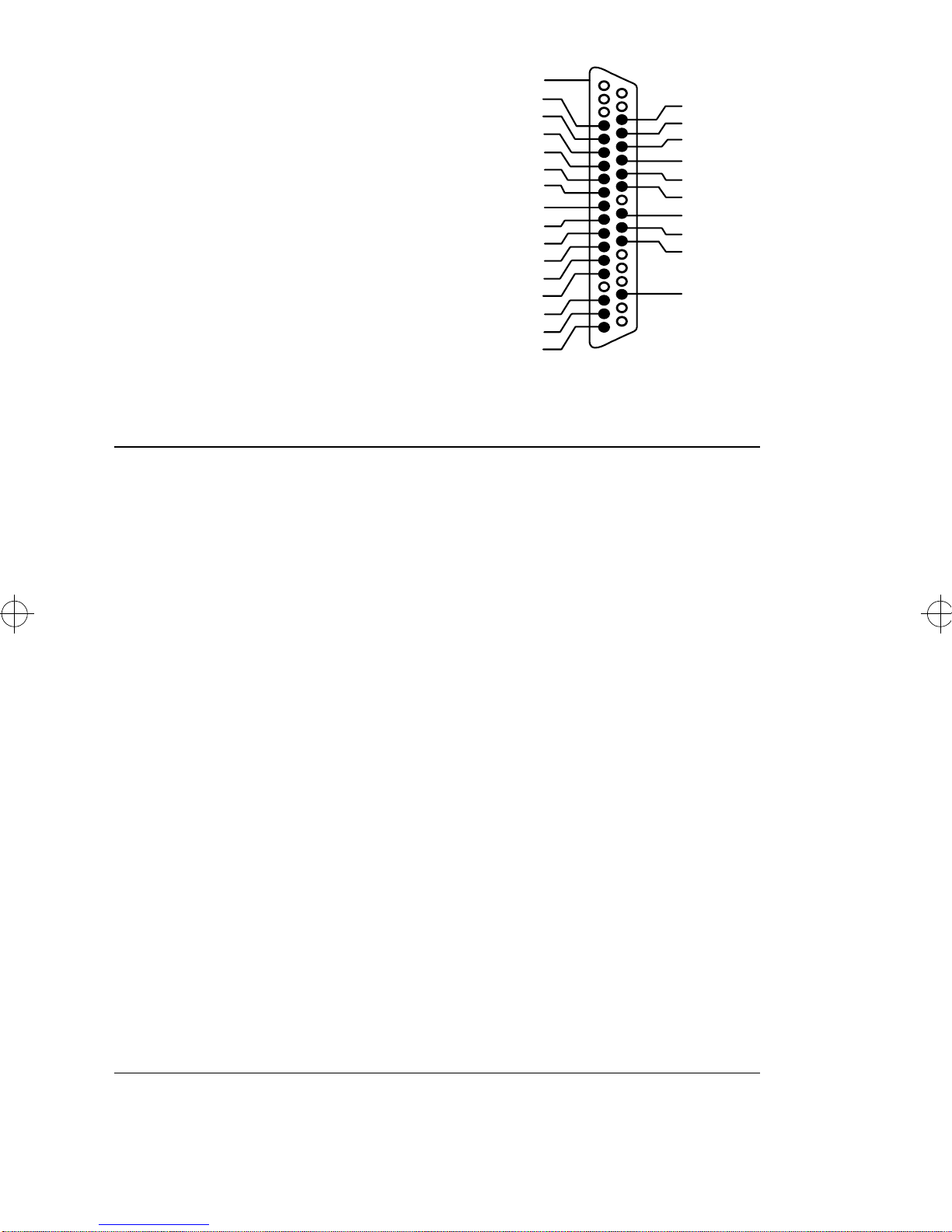
The V.35 Interface
A pin-out diagram for the V.35
interface is shown in Figure 4. The
signal definitions and names are
listed in Table 5.
Figure 4. V.35 Interface
PGND
RXD+
RTS
RI
DCD
SGND
TXD+
CTS
DSR
DTR
CLK+
TEST
RLB
TI
RCLK+
TXD-
RXD-
CLK-
RCLK- TCLK+
TCLK-
A
NN MM
B
Table 5. V.35 Interface Signals
Pin #
Signal Name Direction CCITT #
A PGND Protective Ground Common 101
B SGND Signal Ground Common 102
C RTS Request to Send Output 105
D CTS Clear to Send Input 106
E DSR Data Set Ready Input 107
F DCD Data Carrier Detect Input 109
H DTR Data Terminal Ready Output 108
J RI Ring Indicator Input 125
L TEST Local Loopback Activation Output 141
N RLB Remote Loopback Output 140
P TXD+ Transmit Data Output 103A
R RXD+ Receive Data Input 104A
S TXD- Transmit Data Output 103B
T RXD- Receive Data Input 104B
U CLK+ Transmit Clock (DTE) Output 113A
V RCLK+ Receive Clock (DCE) Input 115A
W CLK- Transmit Clock (DTE) Output 113B
X RCLK- Receive Clock (DCE) Input 115B
Y TCLK+ Transmit Clock (DCE) Input 114A
AA TCLK- Transmit Clock (DCE) Output 114B
NN TI Test Indicator Input 142
203086-1.FM5 Page 12 Friday, February 28, 1997 10:35 AM
EiconCard P92 Installation Guide 13
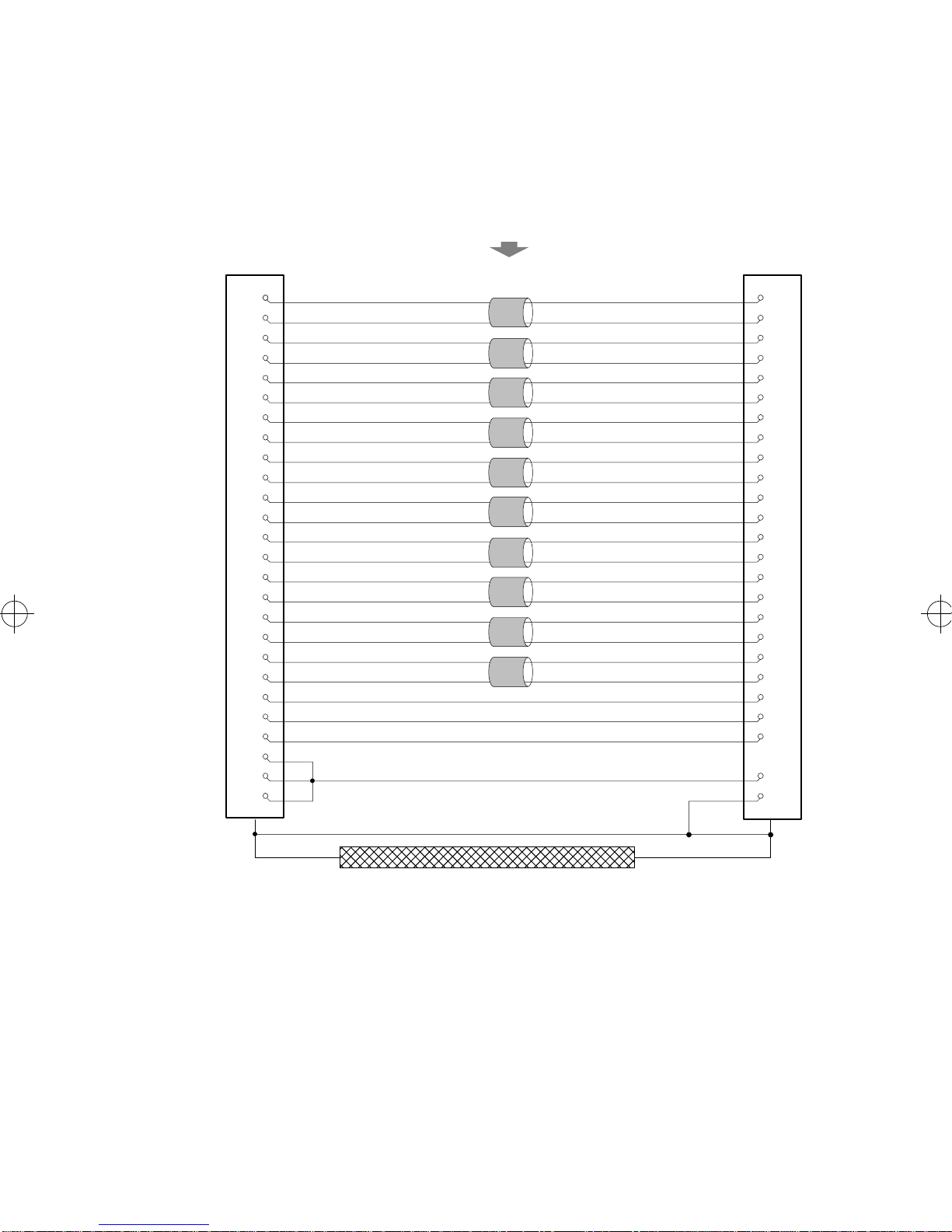
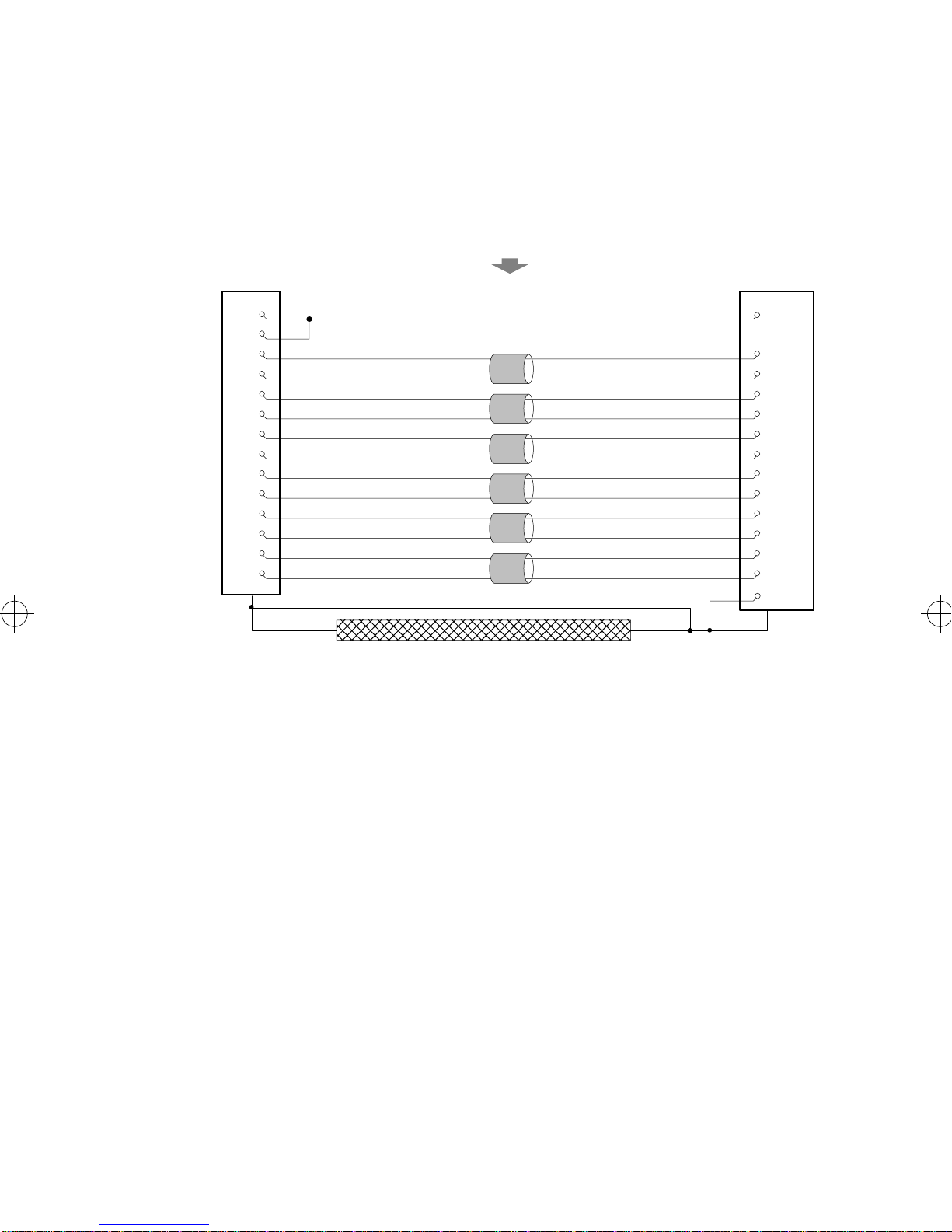
VHSI—V.35 Connections
The wiring diagram below shows the connections required to
construct a VHSI—V.35 cable. For the additional information
required to construct your own cables, see “Cable Construction
Information,” on page 21.
Figure 5. VHSI—V.35 Connections
VHSI
V.35
DRAIN WIRE
5
23
6
24
10
18
8
U
26
W
9
D
11 E
13 F
18 J
21 L
25
C
30
H
33
34
36
BRAID
N
NN
B
A
Y
AA
R
T
V
X
P
S
TWISTED PAIRS
(MANDATORY)
1
3
19
14
32
203086-1.FM5 Page 13 Friday, February 28, 1997 10:35 AM
14 EiconCard P92 Installation Guide
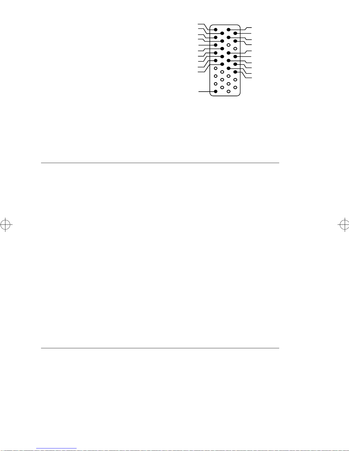
The EIA-530 Interface
A pin-out diagram for the EIA-530
interface is shown in Figure 6. The
signal definitions and names are
listed in Table 6.
Figure 6. EIA-530 Interface
TRXC+
RTXC+
DTR+
CLK+
RXD-
RTS-
DCD-
TXD-
TRXC-
RTXC-
CTS-
DSR-
DTR-
TEST
RLB
TI
CLK-
PGND
RXD+
RTS+
1
DCD+
SGND
TXD+
CTS+
DSR+
25
13
14
Table 6. EIA-530 Interface Signals
Pin #
Signal Name Direction CCITT # EIA #
1 PGND Protective Ground Common 101 -
2 TXD+ Transmit Data Output 103A BA(A)
3 RXD+ Receive Data Input 104A BB(A)
4 RTS+ Request to Send Output 105A CA(A)
5 CTS+ Clear to Send Input 106A CB(A)
6 DSR+ Data Set Ready Input 107A CC(A)
7 SGND Signal Ground Common 102B AB
8 DCD+ Data Carrier Detect Input 109A CF(A)
9 RTXC- Receive Clock (DCE) Input 115B DD(B)
10 DCD- Data Carrier Detect Input 109B CF(B)
11 CLK- Transmit Clock (DTE) Output 113B DA(B)
12 TRXC- Transmit Clock (DCE) Output 114B DB(B)
13 CTS- Clear to Send Output 106B CB(B)
14 TXD- Transmit Data Output 103B BA(B)
15 TRXC+ Transmit Clock (DCE) Input 114A DB(A)
16 RXD- Receive Data Input 104B BB(B)
17 RTXC+ Receive Clock (DCE) Input 115A DD(A)
18 TEST Local Loopback Output 141A LL
19 RTS- Request to Send Output 105B CA(B)
20 DTR+ Data Terminal Ready Output 108A CD(A)
21 RLB Remote Loopback Output 140A RL
22 DSR- Data Set Ready Input 107B CC(B)
23 DTR- Data Terminal Ready Output 108B CD(B)
24 CLK+ Transmit Clock (DTE) Output 113A DA(A)
25 TI Test Indicator Input 142A TM
203086-1.FM5 Page 14 Friday, February 28, 1997 10:35 AM
EiconCard P92 Installation Guide 15
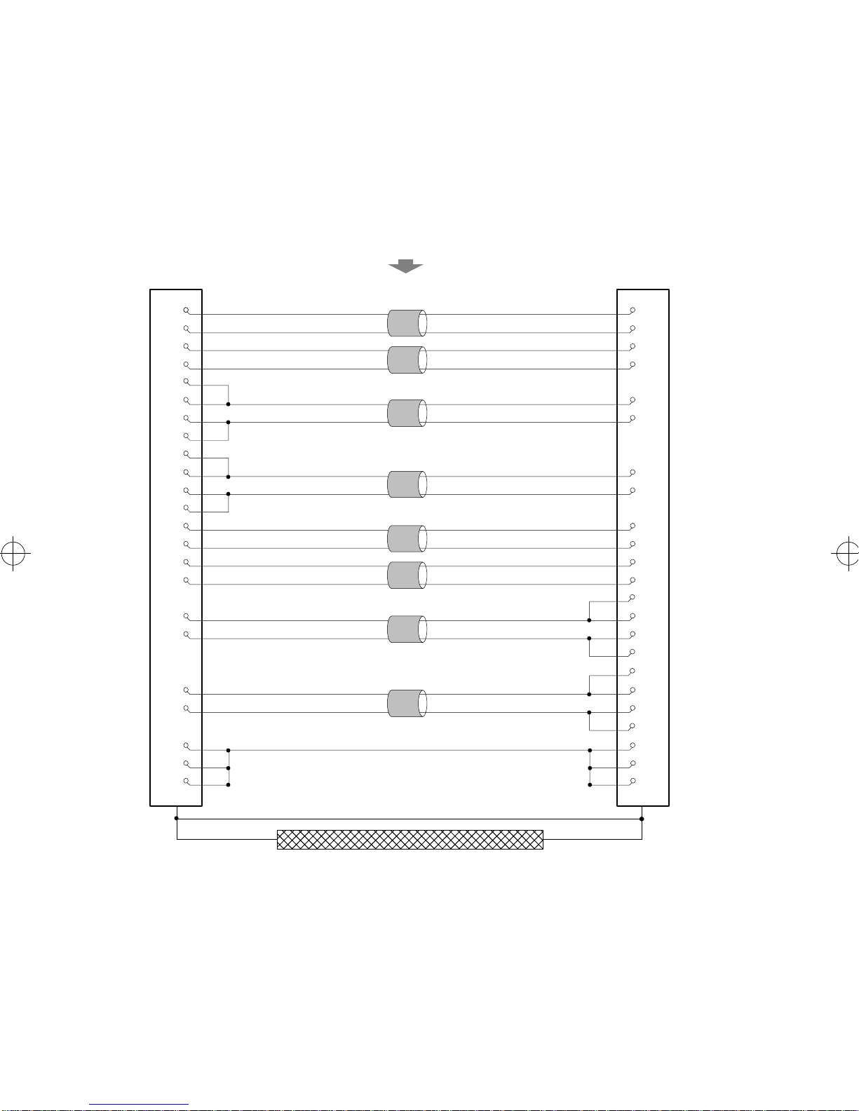
VHSI—EIA-530 Connections
The wiring diagram below shows the connections required to
construct a VHSI—EIA-530 cable. For the additional information
required to construct your own cables, see “Cable Construction
Information,” on page 21.
Figure 7. VHSI—EIA-530 Connections
VHSI
EIA-530
DRAIN WIRE
4
22
5
23
6
24
7
25
8 17
26 9
9 5
27 13
11 6
29 22
12 20
30 23
13 8
31
17
35
21 21
33
34
BRAID
10
24
11
18
25
2
14
15
12
3
16
4
19
TWISTEDPAIRS
(MANDATORY)
7
1
2
19 1
203086-1.FM5 Page 15 Friday, February 28, 1997 10:35 AM
16 EiconCard P92 Installation Guide
The V.36/RS-449 Interface
A pin-out diagram for the V.36/
RS-449 interface is shown in
Figure 8. The signal definitions and
names are listed in Table 7.
Fig. 8. V.36/RS-449 Interface
PGND
RXD+
RTS+
1
RI
DCD+
GND
TXD+
TRXC+
RTXC+
CTS+
DSR+
DTR+
CLK+
RXD-
RTS-
DCD-
TXD-
TRXC-
RTXC-
CTS-
DSR-
DTR-
TEST
RLB
TI
CLK-
37
19
20
Table 7. V.36/RS-449 Interface Signals
Pin #
Signal Name Direction CCITT #
Case PGND Protective Ground Common 101
4 TXD+ Transmit Data Output 103A
5 TRXC+ Transmit Clock (DCE) Input 114A
6 RXD+ Receive Data Input 104A
7 RTS+ Request to Send Output 105A
8 RTXC+ Receive Clock (DCE) Input 115A
9 CTS+ Clear to Send Input 106A
10 TEST Local Loopback Activation Output 141A
11 DSR+ Data Set Ready Input 107A
12 DTR+ Data Terminal Ready Output 108A
13 DCD+ Data Carrier Detect Input 109A
14 RLB Remote Loopback Output 140A
15 RI Ring Indicator Input 125A
17 CLK+ Transmit Clock (DTE) Output 113A
18 TI Test Indicator Input 142A
19 GND DTE Common Return Common 102A/B
22 TXD- Transmit Data Output 103B
23 TRXC- Transmit Clock (DCE) Output 114B
24 RXD- Receive Data Input 104B
25 RTS- Request to Send Output 105B
26 RTXC- Receive Clock (DCE) Input 115B
27 CTS- Clear to Send Output 106B
29 DSR- Data Set Ready Input 107B
30 DTR- Data Terminal Ready Output 108B
31 DCD- Data Carrier Detect Input 109B
35 CLK- Transmit Clock (DTE) Output 113B
203086-1.FM5 Page 16 Friday, February 28, 1997 10:35 AM
EiconCard P92 Installation Guide 17
VHSI—V.36/RS-449 Connections
The wiring diagram below shows the connections required to
construct a VHSI—V.36/RS-449 cable. For the additional
information required to construct your own cables, see “Cable
Construction Information,” on page 21.
Figure 9. VHSI—V.36/RS-449 Connections
VHSI
V.36 / RS-449
DRAIN WIRE
4
22
5
23
6
24
7
25
8 8
26 26
9 9
27 27
11 11
29 29
12 12
30 30
13 13
31
17
35
18
21 10
33
34
20
BRAID
31
17
35
15
14
18
4
22
5
23
6
24
7
25
TWISTEDPAIRS
(MANDATORY)
19
1
2
19 37
203086-1.FM5 Page 17 Friday, February 28, 1997 10:35 AM
18 EiconCard P92 Installation Guide
The X.21 Interface
A pin-out diagram for the X.21
interface is shown in Figure 10.
The signal definitions and names
are listed in Table 8.
Figure 10. X.21 Interface
PGND
1
T(A)
C(A)
R(A)
I(A)
S(A)
B(A)
SGND
T(B)
C(B)
R(B)
I(B)
S(B)
B(B)
PGND
15
8
9
Table 8. X.21 Interface Signals
Pin #
Signal Name Direction CCITT #
1/15 PGND Protective Ground Common 101
2 T(A) Transmit Data (+) Output 103A
3 C(A) Control Signal (+) Output 105A
4 R(A) Receive Data (+) Input 104A
5 I(A) Indication (+) Input 109A
6 S(A) Signal Element Timing (+) Input 115A
7 B(A) Byte Timing (+) Input 114A
8 SGND Signal Ground Common 102
9 T(B) Transmit Data (-) Output 103B
10 C(B) Control Signal (-) Output 105B
11 R(B) Receive Data (-) Input 104B
12 I(B) Indication (-) Input 109B
13 S(B) Signal Element Timing (-) Input 115B
14 B(B) Byte Timing (-) Input 114B
203086-1.FM5 Page 18 Friday, February 28, 1997 10:35 AM
EiconCard P92 Installation Guide 19
VHSI—X.21 Connections
The wiring diagram below shows the connections required to
construct a VHSI—X.21 cable. For the additional information
required to construct your own cables, see “Cable Construction
Information,” on page 21.
Figure 11. VHSI—X.21 Connections
VHSI
X.21
1
19
4
22
5
23
6
24
8
26
11
29 12
12 3
30 10
8
1
9
7
14
4
11
6
13
5
TWISTED PAIRS
(MANDATORY)
2
DRAIN WIRE
BRAID
203086-1.FM5 Page 19 Friday, February 28, 1997 10:35 AM
20 EiconCard P92 Installation Guide
Back-to-Back Connections
The wiring diagram below shows the connections required to
construct a back-to-back VHSI—VHSI cable. Back-to-back
operations are conducted through the V.36 interface. For the
additional information required to construct your own cables, see
“Cable Construction Information,” on page 21.
Figure 12. VHSI—VHSI Connections
VHSI
VHSI
DRAIN WIRE
4
22
6
24
26
23
5
8
13
27 31
25
11 12
29 30
12 11
30 29
7
13
31
BRAID
9
27
25
5
6
24
4
22
17
35
TWISTEDPAIRS
(MANDATORY)
19
7
9
17
35 8
26
23
1
1
219
2
203086-1.FM5 Page 20 Friday, February 28, 1997 10:35 AM
Table of contents


