EIJKELKAMP 09.06 User manual

1
09.06 RAINFALL SIMULATOR
M1.09.06.E© March 2005
OPERATING INSTRUCTIONS
A
B
C
Contents
On these operating instructions ....................................................................................................................... 2
1 Description.................................................................................................................................................. 2
1.1 Rainfall simulator .............................................................................................................................. 2
1.2 Accessories....................................................................................................................................... 3
2 Technical specifications ............................................................................................................................... 4
3 Safety instructions ...................................................................................................................................... 4
4 Calibration .................................................................................................................................................. 4
5 Installation .................................................................................................................................................. 6
6 The use .................................................................................................................................................... 6
7 Application .................................................................................................................................................. 6
8 Troubleshooting........................................................................................................................................... 6
9 Maintenance ............................................................................................................................................... 7
www.eijkelkamp.com
P.O. Box 4, 6987 ZG Giesbeek, NL
T+31 313 880200
F+31 313 880299

2
On these operating instructions
If the text follows a mark (as shown on the left), this means that an important instruction
follows.
If the text follows a mark (as shown on the left), this means that an important warning
follows relating to danger to the user or damage to the apparatus.The user is always
responsible for its own personal protection.
1 Description
With the rainfall simulator, one measures the runoff and soil loss generated by a standardised rainshower on a
plot with standard surface area. The duration, intensity and kinetic energy of the shower are such that a high
sensitivity of the test results for differences in soil properties is obtained.
1.1 Rainfall simulator
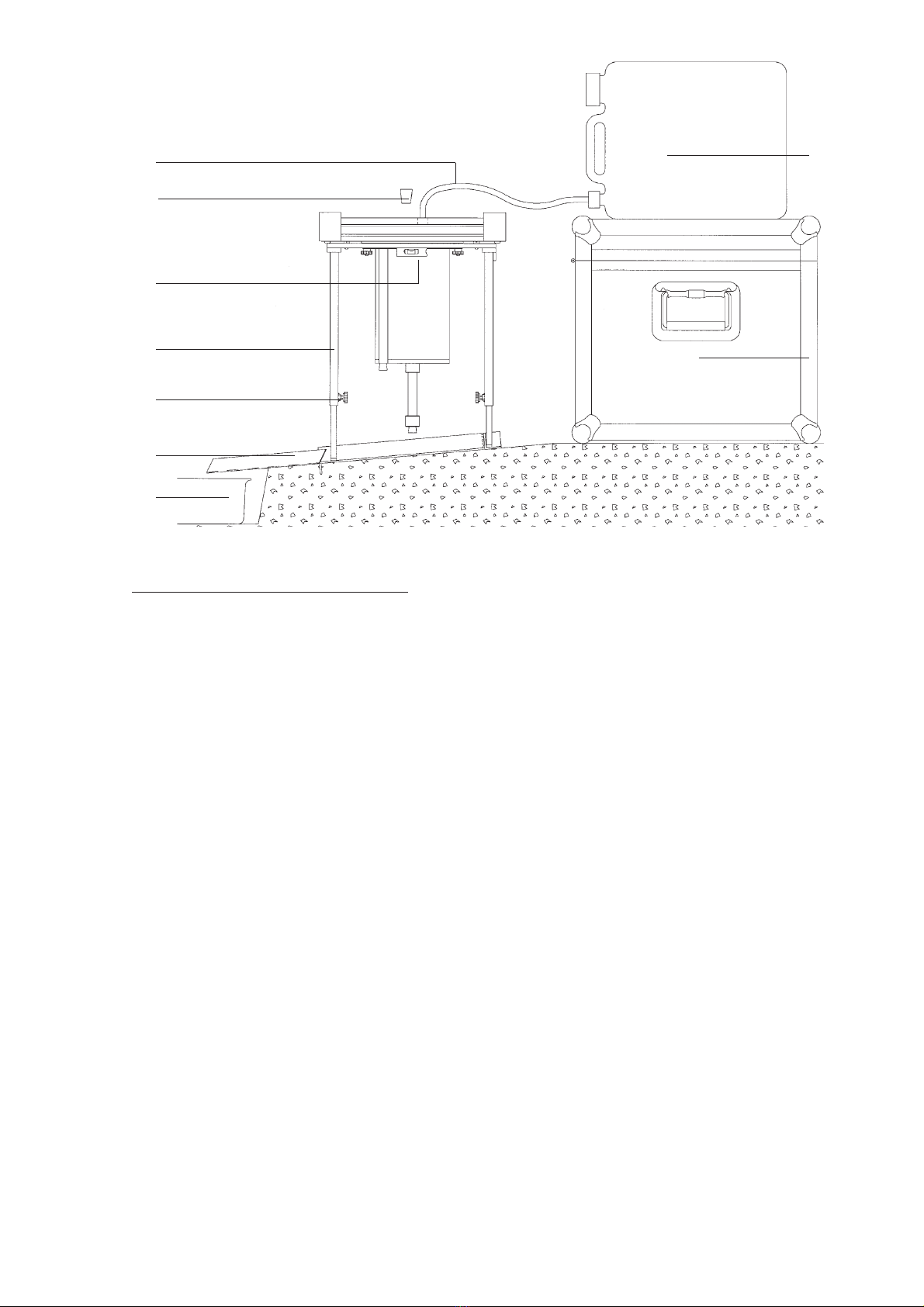
Essentially the rainfall simulator consists of three parts (see figure page 1):
A sprinkler (A) with a built-in pressure regulator for the production of the standard rain shower.
An adjustable support (B) for the sprinkler.
An aluminium ground frame (C), which is placed on the soil and prevents the lateral movement of water
from the test plot to the surrounding soil.
!
14
1
2
3
4
5
6
7
8
12
11
10
9
h

3
Sprinkler
The sprinkler (A) consists of a calibrated cylindrical reservoir (3) with a capacity of approximately 2300 ml, which is
in open connection with the sprinkling head. The waterlevel can be read on the reading pipe (10) which is closed
using a plug (9). Water is released from the sprinkling head through 49 capillaries (14). The pressure head and the
length and the inner diameter of the capillaries determine the release rate. The pressure head on the capillaries can
be increased or decreased by moving the aeration tube (2) upward or downward. The magnitude of this pressure
head regulation is sufficient to correct for influence of the viscosity of the water used on the discharge rate of the
capillaries. It is meant to control the intensity of the required standard shower. The lower ends of the capillaries are
fitted with a short piece of tubing (7). The inner and outer diameters of this tubing control the drop size and the
drop frequency. The sprinkler can be filled through the filling opening, which is normally closed with a plug (8).
Adjustable support
The adjustable support (B) is used for positioning and levelling the sprinkler. Two levels (16) and four knobs (18)
are used to level the support (B) on which the sprinkler is placed. The stainless steel adjustable legs (17) are
positioned on the ground frame (C).
Ground frame
The aluminium ground frame (C) is fixed on the soil using four large nails. The frame is meant to prevent the
lateral movement of water from the testplot to the surrounding soil.
A gutter (19) is installed on the down stream site of the plot for the collection of the runoff and sediment in
the sample collection box (20).
1.2 Accessories
Soil wetting jar
The soil-wetting jar, a plastic box with perforated lid, is used to wet the plot area before sampling.
Water storage tank
With use of a tube, the water storage tank (21) with contents of 20 liter can be connected to the sprinklers’
filling opening. By doing so, the sprinkler can be filled with water.
Sample collection box
Sample material is collected in the plastic sample box with contents of 2 liter.
Sample bucket
The plastic sample box is used to store and transport the sample material.
Transport case
The rainfall simulator and accessories can be stored or transported in the aluminium transport case (22). The
transport case is equipped with two grips, a hinge, and two locks on which the yellow brass padlock can be
fitted.
2 Technical specifications

4
Transport case Outside dimensions: 60 x 48 x 40 cm
Sprinkler Dimensions: 330 x 330 mm
Capillair Length: 10 mm ± 1 mm
Diameter: 0.6 mm ±0.08 mm
Material: Glass
Adjustable support Two waterlevels included, dimension: 305 x 305 mm
Ground frame Aluminium Dimension: 345 x 320 mm
Soil wetting jar Diameter: 14 cm, height: 5.5 cm
Sample collection box Contents: 2 liter
Sample bucket Contents: 1.2 liter
Magnitude of rain simulation 18 mm
Duration of rain simulation 3 min.
Intensity of rain simulation 6 mm/min
Fall height of drops average 400 mm
Diameter of drops 5.9 mm
Mass of drops 0.106 g
Number of capillary tubes 49
Kinetic energy of rain 4 J m-2 mm-1
Kinetic energy of rain shower 72 J m-2
Surface area of test plot 0.0625 m2
Slope of test plot Max. 40%
3 Safety instructions
Adjustment of the adjustable support has to be done before placing the sprinkler.
Only use the water storage tank (21) for transporting clean water.
4 Calibration
To gain representative measurements the required discharge rate is 375 ml per minute. The discharge rate is
related to the water-temperature. Therefore and because of possible clogged capillaries it’s necessary to check
if all capillaries are clear and to calibrate the sprinkler before use on the plot field. Follow the next procedure:
A plot can only be used once. Therefore do not calibrate or test the sprinkler on the plot.
1. Install the ground frame (C) using the four nails.
2. Install the adjustable support (B) on the ground frame (C). Use the two levels (16) and four knobs (18) to
level the support (B).
3. Close the aeration pipe (2) with a plug (1).
4. The sprinkler is placed upside down on the support.
5. Remove the plug (8) out of the filling opening.
6. Use the water storage tank (21) to fill the sprinkler with water. Connect the water storage tank tube (15) to
the water storage tank (21). Install the water storage tank (21) uphill on top of the transport case (22),
above the sprinkler.
7. Connect the tube (15) to the sprinklers’ filling opening as soon as the water starts to flow. If the water
doesn’t flow, suck the tube while holding the end of the tube below the water storage tanks till water starts
to flow.
8. The tube can be disconnected, as the sprinkler is filled and all the air has escaped through the capillaries.
The waterflow can be stopped by moving the tube above the water storage tank (21).
9. After filling the sprinkler, note the water temperature and put the plug (8) in the filling opening.
10.Turn the sprinkler around to its sprinkling position on the support.
!
!
5
11.Adjust the rainfall intensity using the aeration pipe (2). The distance (h, see figure page 2) between the reservoir
and the upper side of the aeration pipe has to be set depending on the measured water temperature. For a
rough indication of the correct setting, the following formula can be used.
h = 100 mm – 0.65 * temperature (°C)
Value 100 mm is the starting position of the aeration tube at the beginning of the calibration (closest to the
required 375 ml/min). Value 0.65 is an average factor for the correction of the temperature, 1 degree
difference equals approx. 4 ml/min in the final result.
The formula has to do with the viscosity of the water. The viscosity of the water depends on the
temperature of the water, so this can influence the intensity of the shower. Before use, you always have to
calibrate to 375 ml/minute. At 10 °C the viscosity is higher, so the aeration pipe must be placed a little bit
higher (>h). At 40 °C, the water has a lower viscosity, so therefore the pipe must be placed a little bit lower.
At the Wageningen University and Research Centre they tested with the following results:
Water temp. Shower h*
10 °C 350 ml/min-1 10 cm
20 °C 375 ml/min-1 9 cm
40 °C 450 ml/min-1 8 cm
h* = top reservoir (3) - top aeration pipe (2)
In practice you better ignore the formula. One should always test and calibrate in order to get 375 ml/min
(all depending on the temperature of the water).
12.Note the water level in the reservoir.
13.Check if the stopwatch works properly and reset.
14.Removing the plug (1) from the aeration pipe (2) starts the simulation. Start the stopwatch.
15.After three minutes, stop the simulation by placing the plug (1) on the aeration pipe (2).
16.Note the water level in the reservoir. If the water level has decreased 375 ml in 1 minute, the sprinkler is
calibrated correctly (outflow = 375 ml/min). Note the distance (h) at this setting. If not calibrated correctly,
repeat step 11-16 and re-adjust the aeration pipe (2). If the distance (h) is increased, the quantity of
sprinkled water per minute will increase.
15
8
16
17
18
19
20
21
22

6
5 Installation
1. Select the soil plot area.
Leave the soil plot unimpaired.
2. Install the ground frame (C) using the four nails. A waterproof connection between the soil and the ground
frame (C) can be made using clay.
3. Fill the soil wetting jar with water and place the lid.
4. At the bottom of the slope, a small trench is made, in which the sample collection box for the collection of
runoff and soil-loss is placed.
5. Install the gutter so that all of the runoff and soil-loss will flow in the sample collection box. Clay can be
used to provide a waterproof connection between the gutter and the soil plot. Be carefull no added clay will
rinse in the sample collection box (20).
6. Install the adjustable support on the ground frame. Use the two levels (16) and four knobs (18) to install the
support level to the desired height.
6 The use
1. If not already done, fill the sprinkler and turn the sprinkler around to its sprinkling position on the support
(B).
2. Ascertain that the ground frame (C), gutter (19) and sample collection box (20) are in place.
3. Note the water level in the reservoir (3).
4. Check if the stopwatch works properly and reset.
5. Removing the plug (1) from the aeration pipe (2) starts the simulation. Start the stopwatch.
6. During the simulation, move the sprinkling head sideways in all horizontal directions, to make sure that the
drops emerging from the capillaries are equally and randomly distributed over the test plot. This can be
done by hand, as the sprinkling head slides easily on the upper rim of the support over predetermined
distances.
7. After three minutes, place the plug (1) in the aeration pipe (2) to stop the simulation.
8. Sediment left behind in the gutter (19) is added to the contents of the sample collection box (20) with the
aid of a wiper.
9. Put al the material left in the sample collection box (20) in the sample bucket. Now the material can be
transported easily to the laboratory, where the amounts of runoff and sediment are determined by weighing
and drying.
10.Note the water level in the reservoir (3).
11.Before storage or transportation, all parts have to be clean.
7 Application
The rainfall-simulator can be used in the field as well as in the laboratory.
The results obtained allow to compare different soil types and crusts on:
1. Erodibility
2. Runnoff (as a percentage of total simulated rain)
8 Troubleshooting
In case of windy circumstances, it is possible the wind affects the simulation. To prevent this, in most cases
it is sufficient to place yourself between the frame and the wind direction.

7
9 Maintenance
Cleaning the sprinkler has to be done thoroughly since clogged up capillaries may cause the simulation to be
useless. Clean the capillaries thoroughly with the supplied 0.5-mm drill or a needle.
Before storage or transportation, all parts have to be clean.
For replacing the round sealing (4), remove the four nuts (11) and the reservoir (3), replace the round sealing
(4) and reasseble the sprinkler using the four nuts (11).
For replacing sealing (5), remove the eight screws (12), the reservoir and assembled sprinkler part. Replace
the sealing. Reassemble the sprinkler using the eight screws (12).
For replacing sealing (6) remove the eight screws (13) and the assembled sprinkler part. Replace the sealing.
Reassemble the sprinkler using the eight screws (13).
Nothing in this publication may be reproduced and/or made public by means of print, photocopy, microfilm or any other means without
previous written permission from Eijkelkamp Agrisearch Equipment.
Technical data can be amended without prior notification.
Eijkelkamp Agrisearch Equipment is not responsible for (personal) damage due to (improper) use of the product.
Eijkelkamp Agrisearch Equipment is interested in your reactions and remarks about its products and operating instructions.
Table of contents
Popular Irrigation System manuals by other brands


Tyco Fire Product
Tyco Fire Product CENTRAL Optima Design & installation guide

Tyco Fire Product
Tyco Fire Product SIN S3244 manual

Nelson
Nelson RainTrain2 instruction manual

Viking
Viking MICROFAST VK325 Technical data

Perrot
Perrot RollcarT-V-2 Operating manual / spare parts list

DIG
DIG GE2050 installation instructions


