Eircom Advantage 1500 User manual

eircom advantage 1500
System Installation

Advantage 1500 System Installation
3
Specifications subject to change without notice. Facilities described may or may not be
supported by your network.This documentation refers to software version 53.708 Revision 1.
DM 834

Advantage 1500 System Installation
4
Table of Contents
2.
Advantage 1500 System Installation................................... 6
2.1 Control Unit Specification .....................................................................................6
2.1.1
Physical Dimensions...............................................................................................................6
2.1.2
Weight.....................................................................................................................................7
2.1.3
Operating Voltage ...................................................................................................................7
2.1.4
Enviromental Specification .....................................................................................................7
2.2
Installing the Control Unit ..............................................................................7
2.2.1
Location ..................................................................................................................................7
2.2.2
Equipment...............................................................................................................................7
2.2.3
Removing the Access cover ...................................................................................................8
2.2.4
Exposed Access Area.............................................................................................................8
2.2.5
Wall mounting the unit ............................................................................................................9
2.3
Wiring Connections .....................................................................................10
2.3.1
Terminal Connectors in the Access Area ............................................................................10
2.3.2
Cage clamp connectors ........................................................................................................11
2.3.3
Wiring the Extensions ...........................................................................................................11
2.3.4
Function LED’s in the access area .......................................................................................12
2.4
Installing the System Phones and DSS Module ..........................................13
2.4.1
Connecting the DSS Module ................................................................................................13
Screws 13
Advantage Executive Phone to DSS Connect Cord ................. 13
2.4.2
Programming the Function Keys ..........................................................................................14
2.5
Analogue extensions...................................................................................15
2.5.1
Connecting Analogue Phones ..............................................................................................15
2.5.2
Calling Line Identity (CLI) .....................................................................................................15
2.5.3
Recall recognition .................................................................................................................15
2.5.4
Analogue Extension electrical characteristics ......................................................................15
2.6
Internal/External (S/T) ISDN basic access Interface ...................................16
2.7
Connecting to the DECT Interface (not supported) .....................................17
2.8
Connecting ISDN lines ................................................................................17
2.9
Installing Modules and Ancillary Equipment................................................18
2.9.1
Replacing the NAND voice card by an Applications card.....................................................19
2.9.2
Installing the Battery Back-Up Module .................................................................................20
3.9.3
Installing the Analogue (FSK) CLI Module ...........................................................................21
3.9.4
Installing the analogue Modem Module................................................................................22
2.10
Music-on-Hold, external source or internal melody .....................................23
2.11
Door Phone.................................................................................................24
2.12
Connecting the Central Bell ........................................................................26
2.13
Powering Up the System.............................................................................26
2.14
IMPORTANT SAFETY NOTICES ...............................................................27
2.15
Ethernet LAN Communication and IP addresses ........................................28
2.15.1
Connecting to the Ethernet Port - .........................................................................................28
2.15.2
IP Configuration ....................................................................................................................28
2.15.3
IP Connection Testing ..........................................................................................................29
2.16
Call Logging ................................................................................................30
2.16.1
Call Logging over the ethernet port ......................................................................................30
2.16.2
Call Logging over the serial port ...........................................................................................31
2.16.3
Call Logging format table......................................................................................................32
2.16.4
Logging Incoming Calls ........................................................................................................33
2.16.5
Logging Outgoing Calls ........................................................................................................33

Advantage 1500 System Installation
5
2.16.6
Logging Voice Mail Calls ......................................................................................................33
2.16.7
Logging Transfer Calls..........................................................................................................33
2.16.8
Logging Externally Diverted Calls.........................................................................................34
2.16.9
Logging Auto-attendant Calls ...............................................................................................34
2.16.10 Logging Internet Calls...........................................................................................................34
2.16.11 Logging Time From Network Calls .......................................................................................34
2.16.12 Logging Remote Access Calls.............................................................................................35
2.16.13 Logging Software Download Calls.......................................................................................35
2.16.14 Logging 3-Party Conference Calls.......................................................................................35
2.16.15 Roaming PIN .......................................................................................................................35
2.16.16 Advice Of Charge (AOC) .....................................................................................................35
2.17
Data Call and Diagnostic Logging...............................................................36
2.17.1
ISP Call logging ....................................................................................................................36
2.17.2
Website Access logging........................................................................................................36
2.17.3
Streaming Diagnostic Logging..............................................................................................37
2.17.4
Buffered Diagnostic Logging.................................................................................................37
Advantage 1500 System Installation
6
2. Advantage 1500 System Installation
Important: Only qualified service personnel should carry out installation of the system
Please refer to the Safety notices (2.14) before installation.
2.1 Control Unit Specification
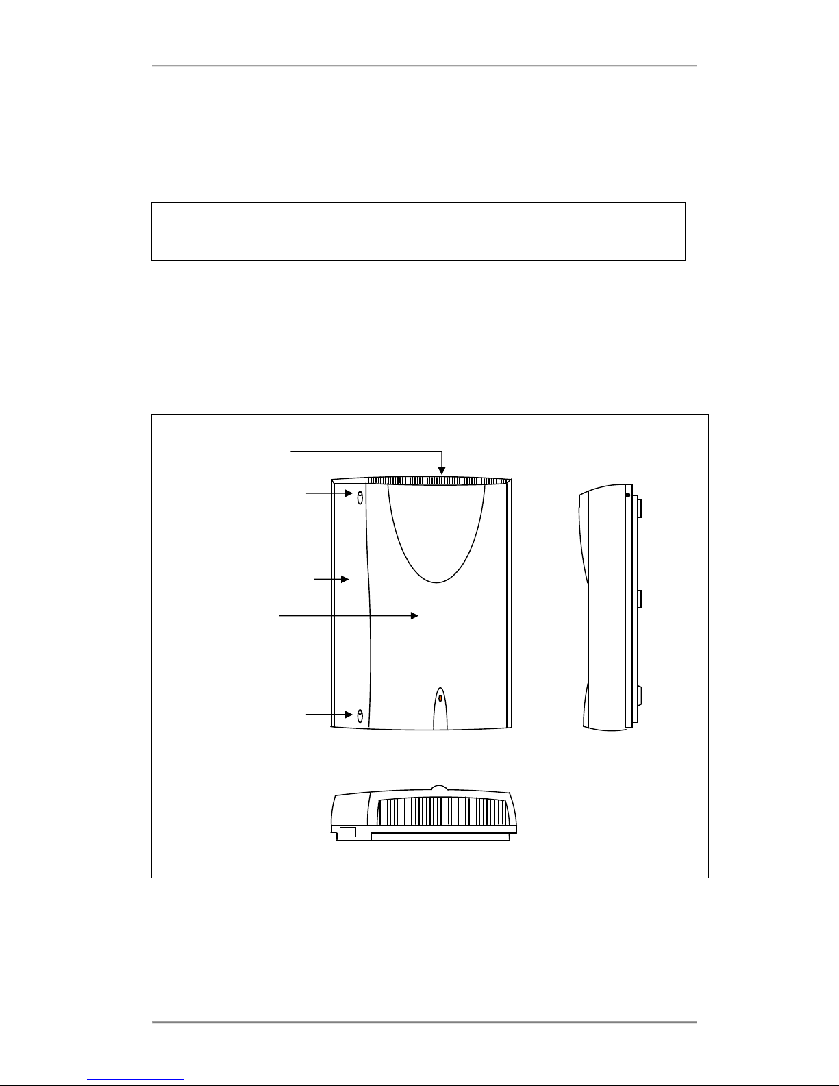
The control unit comprises a printed circuit board (PCB) housed within a 3-part enclosure
which is constructed from robust ABS plastic. The three enclosure parts consist of the Access
Cover, Top Cover and Base. The access cover may not be opened without the use of a tool.
The access cover encloses the connection terminals to which the installer has to have access
for the correct installation of the system.
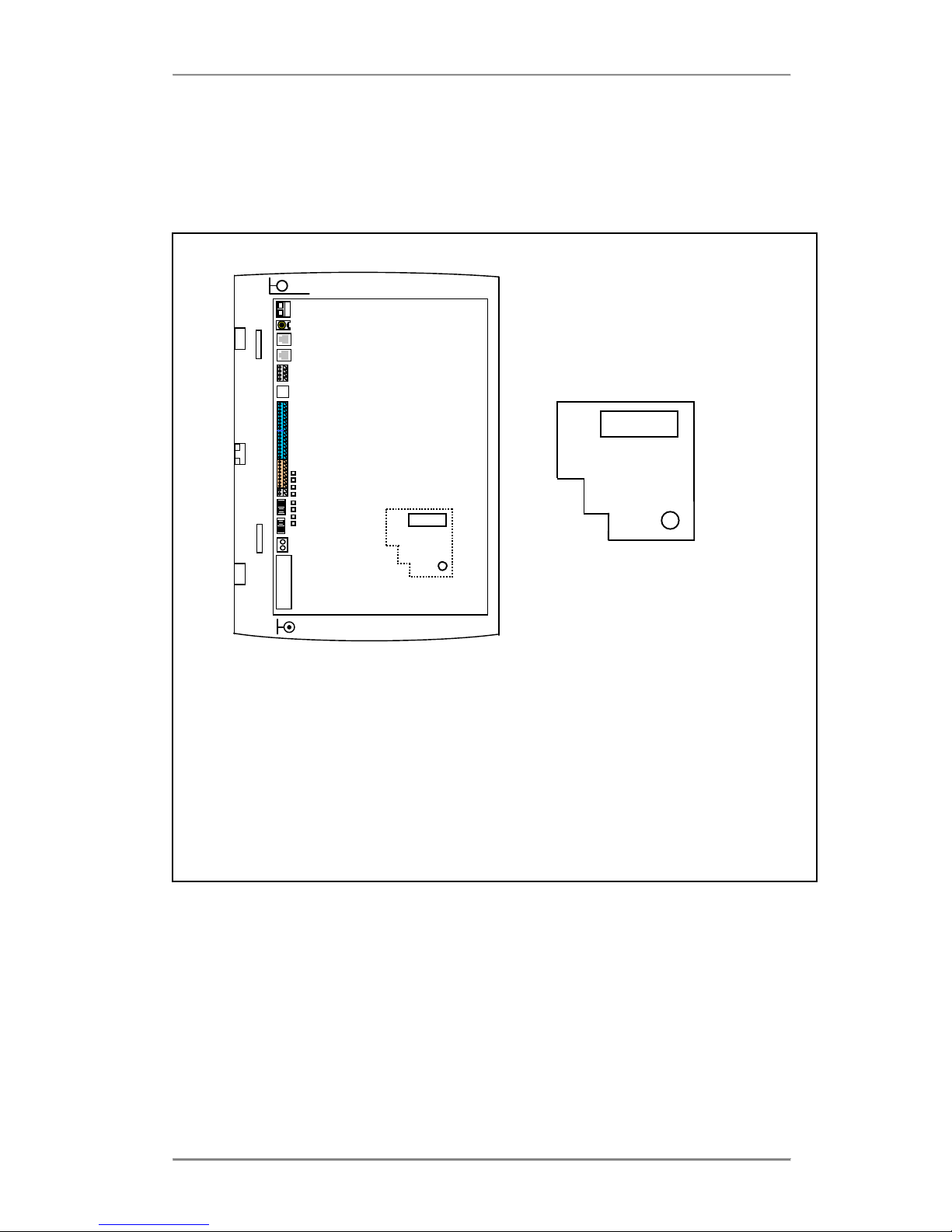
2.1.1 Physical Dimensions
The physical dimensions of the Advantage 1500 control unit are as follows:
354mm (H) x262mm (W) x 85mm (D)
Access Cover
Top Cover
Power
LED
i:BOX
Access Cover
Screw
Ventilation Grill
Access Cover
Screw

Advantage 1500 System Installation
7
2.1.2 Weight
The weight of the Advantage 1500 control unit is approximately 3.0 Kg.
2.1.3 Operating Voltage
The operating voltage and maximum power consumption of the Advantage 1500 control unit is
as follows:
Mains voltage 220 V ±10% @ 50Hz
Max power consumption 33W
2.1.4 Enviromental Specification
Specification
Value
Operating temperature
- 5C to +40C
Humidity
10% to 90% Non-condensing
Maximum AC V/A
46 VA
Maximum input power
33 W
Maximum input current at 230 VAC
0.2 A
Maximum input current at 180 VAC
0.25 A
Power Factor
0.7
Extreme working conditions
- 5C to +50C
Storage temperature
-20C to + 70C
Storage Humidity
10% to 90% Non-condensing
2.2 Installing the Control Unit
2.2.1 Location
Find a location which is:
easily accessible, sufficiently spacious and well lit to allow you to wire the system.
isolated from plumbing or electrical wiring
within 2m of the nearest power point
within convenient reach of the NTU (ISDN line socket) or analogue lines
not exposed to extremes of temperature, humidity, dust, chemicals or direct sunlight.
it is especially important that you allow at least 300mm clearance from the left side of the
mounted unit to allow for unhinging the access cover.
2.2.2 Equipment
Make sure you have the correct tools:
Wall-mounting template (supplied)
2 support screws, 1 fixing screw and rawl plugs (they are supplied in the access area)
Drill and chuck-key
6mm drill bit
Flat head screwdriver
Wire stripper
Snips and Cable Cleats
Advantage 1500 System Installation
8
1.5m Male-Male RJ45 ISDN Line Cords (supplied)
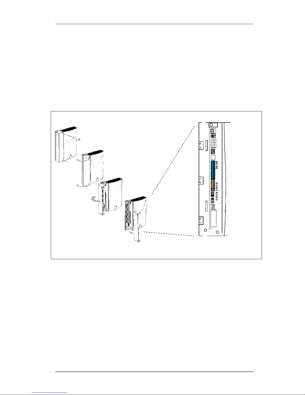
2.2.3 Removing the Access cover
Removal of the access cover exposes the Access Area. This houses the terminals for the
connection of all the devices supported by the Advantage 1500.
To remove the cover:
1. Unscrew the top and bottom screws.
2. Rotate the cover through 90°in the direction shown in the picture below.
3. Lift the cover away from the unit.
Exposed Access area
2.2.4 Exposed Access Area
1. Plastic Breakouts.
Plastic breakout points are provided on the edge of the access area as shown. These
areas are indicated by indents in the plastic and provide space for the wires to enter the
control unit. To create the breakout points simply grip the indented area with a pliers and
bend firmly until the plastic gives way.
2. Cable Ties supports.
There are 2 cable tie supports provided in the access area. All exposed wiring can be neatly
bundled using cable ties attached to the cable tie supports to help secure and consolidate
the wiring connections.
3. Control Unit fixing screw position.
The control unit fixing screw position provides space for the fixing screw to fix the contol
unit to the wall for wall mounting
1
1
2
2
3
4
4
Advantage 1500 System Installation
9
4. Top cover screws.
These 2 screws if removed will allow access to the main control board.
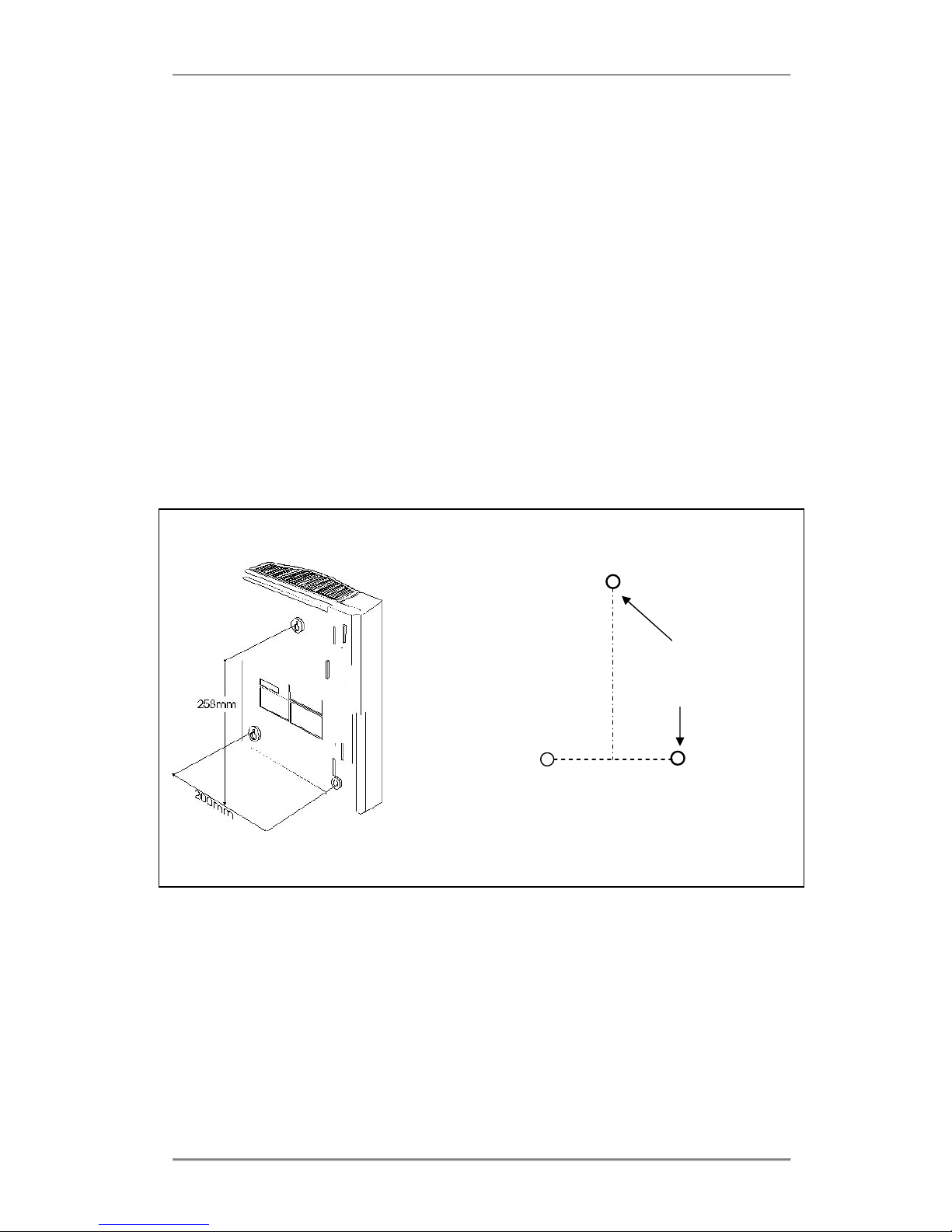
2.2.5 Wall mounting the unit
Follow the steps below to mount the Advantage 1500 on the wall. Note that the mounting
screws and rawl plugs are located inside the access area.
1. Mark on the wall the location of the three screw holes using the supplied template.
2. Drill holes and insert rawl plugs.
3. With the Access Cover removed (see previous section), the supporting and the fixing screw
holes are exposed.
4. Insert the two support screws into the support holes and screw down, leaving a 5mm
clearance from the surface of the wall.
5. Place the keyhole slots of the system over the supporting screws.
6. Insert the remaining screw into the fixing hole, via the access area and screw down. DO
NOT OVER-TIGHTEN as this may damage the plastic housing!
The system is now ready for wiring.
Template showing screw hole positions
Fixing Screw
via access
cover
Supporting screw
holes for the key
hole slots
Advantage 1500 System Installation
10
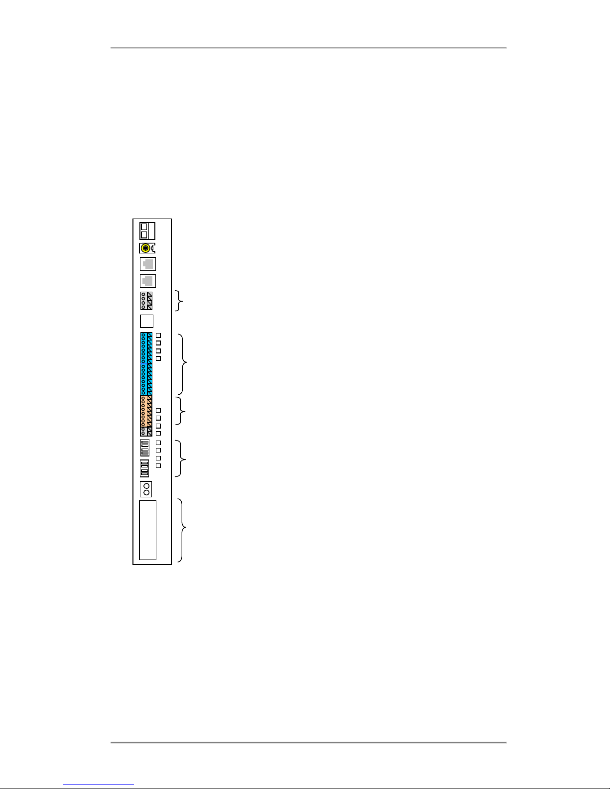
Battery Back-up port
External music-on-hold port
Ethernet LAN port
Ethernet WAN port ( to ADSL ), redundant
2 Relay ports for Doorphone operation
2-wire DSL interface, redundant
Analogue ports ( 8 a/b extensions) Numbered 15-22 by default
Digital ports ( 4 digital extensions) Numbered 11-14 by default
Central Bell
4 PSTN analogue line ports L1 to L4
Protective Earth, screw terminal
3 RJ45 connectors with the following functions :
- T1 is permanently configured for the connection of an ISDN BRI Interface
- S/T is switchable to be a public T interface or an internal So Bus.
- DECT is a non-powered So interface for connection to a DECT base station,
redundant
2.3 Wiring Connections
2.3.1 Terminal Connectors in the Access Area
The following diagram illustrates the terminal layout of the Advantage 1500. All terminal
connectors are located within the access area.
The terminal blocks use the following types of connectors:
oCage clamp connectors are used for the connection of back-up battery, relay driven
devices, analogue / system phone extensions, So-Bus Interface and central bell.
oRJ-45 connectors are used for the connection of the ISDN Lines, So-Bus Interface,
Ethernet LAN ports and 2-wire DSL (redundant)
oPhono-Jack connectors are used for the connection of the external Music-on-Hold.
oKrone IDC connectors are used for the connection of the analogue PSTN lines
oScrew terminals are used for the connection of a protective Earth.

Advantage 1500 System Installation
11
2.3.2 Cage clamp connectors
To connect the wires to the cage clamp connectors, follow the steps below:
1. Insert a non-conducting tool into the groove of cantilever (note that no tool is supplied with
the system)
2. Push cantilever in the direction shown Insert bared wire into the aperture
3. Release cantilever.
2.3.3 Wiring the Extensions
Prepare the wires of the cables and connect them to the appropriate extension terminal blocks
as described above.
Wall-mount the extension telephone sockets. Route the extension cable to the Advantage 1500
system observing good building wiring practice by maintaining at least 50mm clearance
between the extension cable and mains power cable, line or other building cable.
Advantage system phones and analogue telephones are connected to the system using 2 wires
which should be connect to the a and b terminals.
Advantage 1500 System Installation
12
2.3.4 Function LED’s in the access area
There are 12 function LED’s located in the access area which provide visual indications of the
state of the T interfaces, the PSTN lines, the ethernet connectivity and the ADSL functionality.
LED No.
Name
Function
LD1400
SYS LAN
LNK
This LED will light if the system detects the presence of an ethernet
connection to the LAN port when a DSL module is not connected.
LD1401
SYS LAN
COL
This LED will light if the system detects a data collision on the
ethernet connection to the LAN port when a DSL module is not
connected.
LD1402
DSL LAN
LNK
This LED will light if the system detects the presence of an ethernet
connection to the LAN port when a DSL module is connected
LD1403
DSL WAN
LNK
This LED will light if the system detects the presence of an ethernet
connection to the WAN port when a DSL module is connected
LD1605
Future functionality
LD1604
This LED will light if the system detects the presence of an ISDN line
connected to the T2 interface
LD1603
This LED will light if the system detects the presence of an ISDN line
connected to the T1 interface
LD1602
Future functionality
LD7004
This LED will light if the system detects the presence of an PSTN line
connected to the L1 interface.
LD7003
This LED will light if the system detects the presence of an PSTN line
connected to the L2 interface.
LD7002
This LED will light if the system detects the presence of an PSTN line
connected to the L3 interface.
LD7001
This LED will light if the system detects the presence of an PSTN line
connected to the L4 interface.
LD1400 LD1401 LD1402 LD1403 LD1605 LD1604 LD1603 LD1602
LD7004 LD7003 LD7002 LD7001
DSL Operation
Analogue Lines
T2 T1 L4 L3 L2 L1

Advantage 1500 System Installation
13
2.4 Installing the System Phones and DSS Module
The Advantage digital key sets, either the Executive or the Standard version, may be
connected to the digital extension ports using single pair cabling. The system phone line cord is
terminated with a male RJ11 plug with pin-out designations as illustrated in the above diagram.
The Advantage Executive and Standard phones can be desk or wall mounted. For desk
mounting the plinth can be fixed to the base in two ways to give high or low viewing angle. The
plinth is fixed to the base of the phone by sliding the tabs on the plinth into the slots on the
phone base.
The Executive and the Standard phone can be wall mounted. To wall mount either system
phone, the plinth is discarded and the phone is fixed using the two screw slots on the base. Fix
the two wall mounting screws 104 mm apart for the Executive phone, 70 mm for the Standard
phone, using the rawl plugs provided.
2.4.1 Connecting the DSS Module
The desktop Executive key set may be equipped with a DSS module for display of the status of
all 12 system extensions.
To install the DSS module, position the DSS module to the right of the Advantage Executive
and turn both upside down. Use the screws supplied with the DSS module to attach the flange
on the DSS module to the lip beneath the cover of the Advantage Executive.
Plug the short cable with an RJ11 plug at each end (Executive phone to DSS connect cord),
supplied with the DSS module, into the “phone” socket on the DSS and then plug the other end
of this cable into the Advantage Executive “line” socket. Connect the RJ11 plug on the line
Advantage Executive Phone to DSS Connect
Cord
Handset Cord
Screws
Line Cord

Advantage 1500 System Installation
14
cord coming from the Advantage control unit into the “line” socket on the bottom of the DSS
module.
The DSS keys, numbered 11 to 34 and 41 to 64, automatically act as direct station select
keys for all extensions connected to the control unit.
2.4.2 Programming the Function Keys
Keys associated with unavailable extensions may be programmed for other functions using the
“Redefine Keys” option on the associated Advantage 1500 key set. Select “Menus”, “Phone
Settings”, “Define Function Key”, “Redefine Keys” and scroll down to, or press, the key to be
defined; its associated led flashes. Select the function to be associated with the key from the
list of options available. Alternatvely the user can program the function keys form Browser
based programming

Advantage 1500 System Installation
15
2.5 Analogue extensions
The Advantage 1500 provides 8 analogue ports in the access area numbered 15 – 22. Plain,
ordinary telephones (Pots) and other approved analogue devices may be connected to the a/b
ports using single pair cabling. Each port is overload and short circuit protected which provides
an additional level of protection when connecting the analogue devices.
2.5.1 Connecting Analogue Phones
The single a, b pair is connected to the analogue terminals ( 15 – 22 ) of the system. All wires
should be inserted securely into the cage clamp terminals ensuring that no exposed copper
wire is visible in the access area. Cable tie supports on the access area can be used to secure
the wiring cables.
2.5.2 Calling Line Identity (CLI)
The Advantage 1500 supports the transmission of CLI (Calling Line Identification) information
to the 8 analogue extensions. To avail of the CLI feature for incoming calls on analogue lines
please ensure that the analogue CLI module is installed on the system.
2.5.3 Recall recognition
Most analogue telephones will have a Recall button ( R ) included on the telephone. This button
is used to generate a hold signal which must be correctly interpreted by the PBX. The
Advantage 1500 recognises the Recall signal timings on most commercially available analogue
telphones and by default supports a range from 90 to 120 msec (approx)
2.5.4 Analogue Extension electrical characteristics
The electrical characteristics of the analogue extensions on the Advantage 1500 are listed
below.
Analogue extension electrical characterstics
On-Hook Voltage 48 Volts
Off-Hook Voltage 8 Volts
Ringing Voltage 64 V (RMS) on 48 V DC
Ringing frequency 25 Hz
Busy Tone Timing 500 ms ON 500 ms OFF
The Advantage 1500 supports high impedance connections to the analogue extension ports
allowing substantially long cable lengths to be used. To provide for an extra long cable
connection on one of the ports, extension 15 accomodates more than twice the impedance of
the other ports as shown in the table below.
Extension
Impedance
Extension Cable Length (*
)
15
1200 Ohms 7 Km
16
504 Ohms 3 Km
17
504 Ohms 3 Km
18
504 Ohms 3 Km
19
504 Ohms 3 Km
20
504 Ohms 3 Km
21
504 Ohms 3 Km
22
504 Ohms 3 Km
(*) These figures assume that 0.5 mm copper conductor cable is being used to connect the
Advantage 1500 System Installation
16
analogue extensions.
2.6 Internal/External (S/T) ISDN basic access Interface
The Advantage 1500 offers one RJ-45 connector permanently configured as T (Line) interface,
and a second RJ45 connector that can be configured by the user as either a T or an internal So
Bus (S Interface).
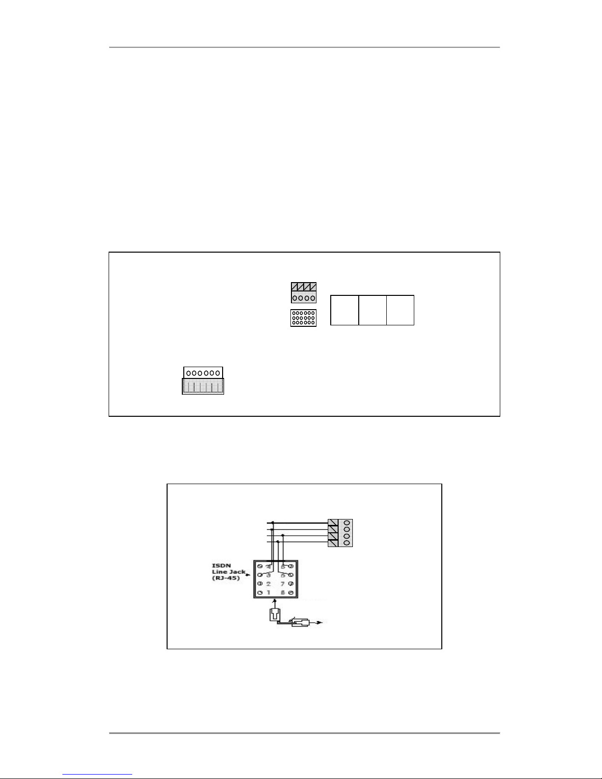
For your convenience, the system provides two connectors that allow the connection of the So-
Bus: an RJ-45 connector and a cage clamp connector. You may connect to one or the other
depending on the type of cabling you wish to route.
Configuration of the So-Bus takes place by moving the plastic shunt on the JP39 Jumper to the
lower position on the pins as shown below. (This switches the Transmit and Receive pair
positions on the connector as well as inserting/removing the 40 Volts DC Power Feed for the
Terminals on the S-Bus).
So Bus Connectors
Cage clamp
RJ45
JP39 DECT S/T T1
JP39
T Shunt position on top for T interface
S Shunt position below for So Interface
The S-bus option, if required, must be enabled in Browser Based Programming.
The So-Bus is a 4-wire bus to which up to 8 ISDN terminals may be connected and operates
only in Point to Multipoint mode.
So Bus wiring to the cage clamp connector
Male-Male RJ45 Cable
To connect the So-Bus, just plug the male RJ-45 cable connector into the RJ-45 terminal
connector of the access area marked S/T.
Rx Pin 3
Tx Pin 4
Tx Pin 5
Rx Pin 6
Advantage 1500 System Installation
17
If you are connecting to the So-Bus via the cage clamp connector, then check the diagram
above for pin connections.
2.7 Connecting to the DECT Interface (not supported)
Previous revisions of the Advantage 1500 provided an RJ45 connector for connecting a DECT
basestation unit to the system. The DECT base station connected using a standard ISDN cable
to the socket labelled DECT on the Advantage unit.
DECT S/T T1
Note: 1. 100 Ohm Terminating resistors should be used on the base station side of the
ISDN Cable connection
2. The DECT interface is a non-powered internal So Bus interface.
For more information on using the DECT base station please refer to the Netvox C308 user
guide.
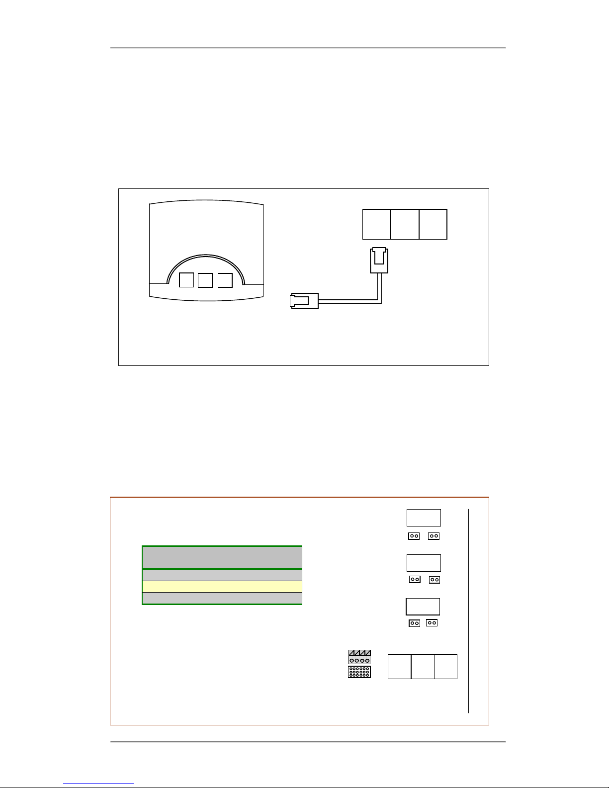
2.8 Connecting ISDN lines
The system allows the connection of up to 2 ISDN lines (T-Interfaces), one of them being
configurable as an internal So-Bus as explained above. A Male-Male RJ45 cable is needed to
connect each ISDN line. The system may be configured to operate in either Point to Point
mode or in Point to Multipoint mode.
T Interface
Jumpers
T1
JP100 & JP101
S/T
JP200 & JP201
DECT
JP300 & JP301
JP301 JP300
JP201 JP200
DECT S/T T1
JP101 JP100
100 Ohm terminating resistors are inserted
onto the receive legs of each RJ45
interface. By removing the relevant jumper
these resistors can be disconnected from
the interface.

Advantage 1500 System Installation
18
Note: If the Advantage 1500 is to be connected in a Point to Multipoint configuration, it MUST
be installed as the last terminal on the bus, otherwise you may need to adjust the jumpers
above.
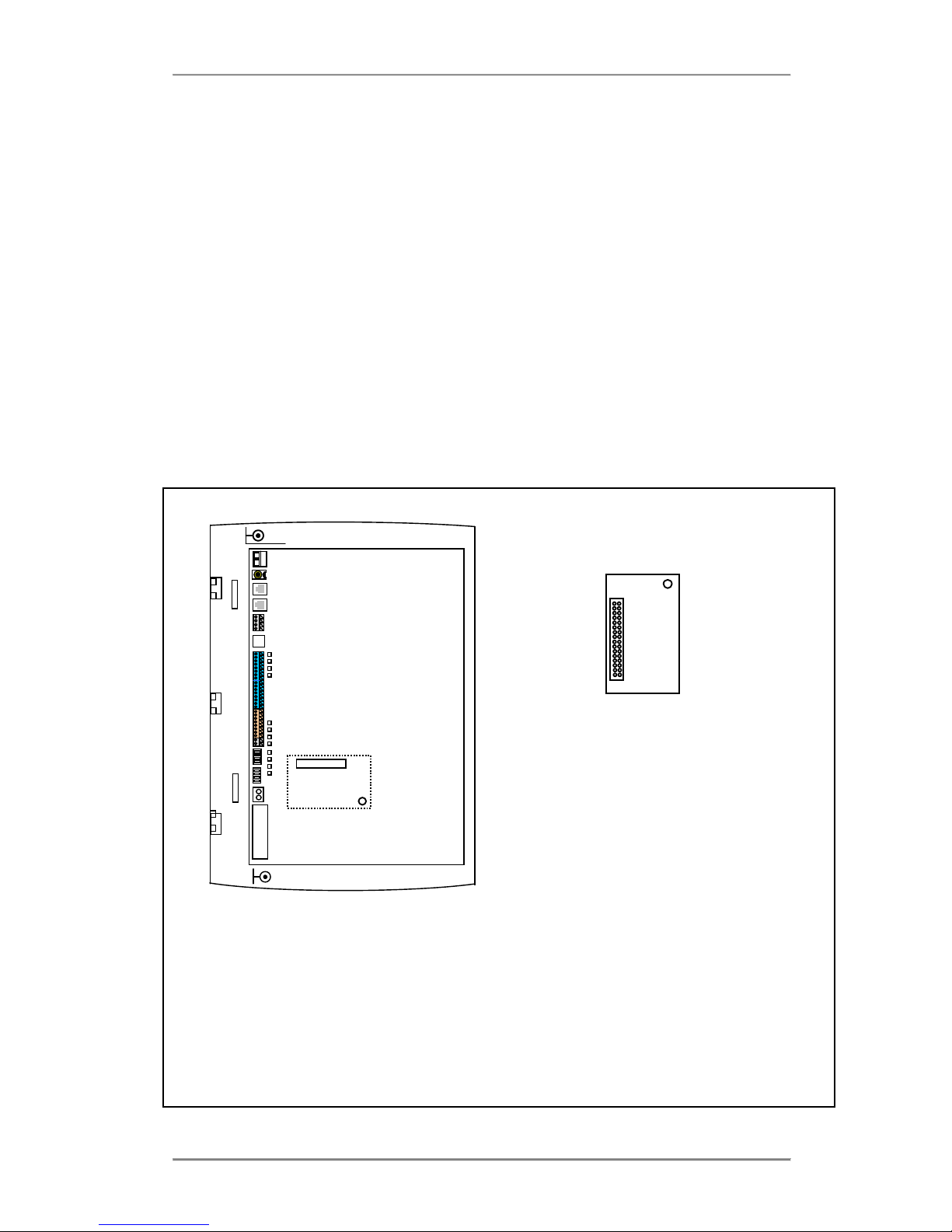
2.9 Installing Modules and Ancillary Equipment
The Advantage 1500 provides for up to 5 plug-in modules to be connected to the motherboard.
These plug-in modules interface to the mother board via edge pin connectors. Each connector
slots into corresponding sockets on the motherboard and is secured by mounting pillars that
insert into holes located on each plug-in module.
Plug
-
in Module
Supporting
Pillars
Connecto
r
No. of Pins
Battery Back
-
up (BBU) charging
Module
3
CN902
12 Pin
ADSL Module (previous only)
2
CN1806
64 Pin
Analogue CLI Module
1
HD7003
36 Pin
NAND voice may be rep
laced by
Applications Module
1
CN1807
32 Pin
Analogue Modem Module
1
CN1505
24 Pin
1. 2.
Inserting the plug-in Modules
Analogue Modem
Module
BBU Charging Module
Appllications
Module
CLI Module
Supporting
Pillar
Advantage 1500 System Installation
19
1. Ensure that the unit is unplugged from the power socket and observe the anti-static
precautions.
2. Align the holes on the plug-in module over the support pillars making sure that the pin
connectors match up with the slots on the main board (1).
3. Press slowly and firmly into place until the module is secured (2).
2.9.1 Replacing the NAND voice card by an Applications card
The Advantage 1500 comes equipped with a NAND voice card (two channels). This may be
replaced by an Applications card for IP functionality and extended Automated Attendant
functionality.
The Advantage 1500 Applications card module alos offers integrated Voice Mail, but has a
more extensive auto attendant solution, capable of storing up to 20 hours of voice in ADPCM
format. It provides up to 22 mailboxes, and up to 8 Voice channels so that up to 8 messages
may be recorded or played simultaneously. It may also be used for call record, music on hold in
wav format and VoIP compression and echo cancellation. The Applications Card software is
downloadable just like the Advantage 1500 system code, allowing the user to upgrade the
software and upload additional applications remotely if required.
Applications card
CN 1807
H 20
To install the Applications card -
•Observe anti-static precautions
•Power down the system
•Remove the control unit main cover
•Remove the NAND voice card that was delivered with the system
•Align the applications card over the mounting pillar H 20 at the lower end of the unit
ensuring that the pins of the 32 way connector line up directly over the 32 pin socket (
CN1807 ).
•Slowly and firmly press down on the applications card until it clicks into place.

Advantage 1500 System Installation
20
2.9.2 Installing the Battery Back-Up Module
For battery backup operation during power cuts, the system may be equipped with an optional
Battery Back-up module (BBU). This comprises a plug-in Battery Back Up Charging module
and an external 12 V battery. During normal operation the BBU module will trickle charge the
battery ensuring that the optimal voltage will be available if the main power supply gets cut.
The system can operate under full load conditions on battery back-up mode for approximateky
2 hours.
Battery Back-Up Charging Module
H2 CN902
H4 H3
External battery housing for Battery
Backup operation
To install the Battery Back Up unit -
•Observe anti-static precautions
•Power down the system
•Remove the control unit main cover
•Mount the Battery Back Up Charging card on the 3 mounting pillars ( H2, H3 & H4 )
above the power supply ensuring that the pins of the 12 way connector line up
•If required, wall-mount the external battery enclosure using the template supplied
•Terminate the interconnecting cable; system end first on the terminals marked B++, B--
•Replace covers
•Power up the system
•Check operation with and without mains power.
Note: The external housing for the battery contains a fuse which is accessable by unscrewing
the plastic screw cap.
Important: Please refer to the Safety Notices ( 2.13 )
Advantage 1500 System Installation
21
3.9.3 Installing the Analogue (FSK) CLI Module
Each Advantage 1500 unit is equipped with an analogue CLI (Calling Line Identity ) module.
This module detects the FSK CLI information presented by the exchange on the PSTN line and
passes this information on to the analogue and digital extensions of the system.
Analogue FSK CLI Module
HD 7003
Small Pillar H17
To Re-install the analogue CLI module –
•Observe the anti-static precautions
•Power down the system
•Remove the control unit main cover
•Align the hole on the analogue modem module over the mounting pillar (Small pillar
H17 ), ensuring that the 36-pin header on the main board ( HD7003 ) lines up with the
connector on the analogue CLI module.
•Press slowly and firmly until the module is secured.
Table of contents
Other Eircom Cordless Telephone manuals


 user manual")


