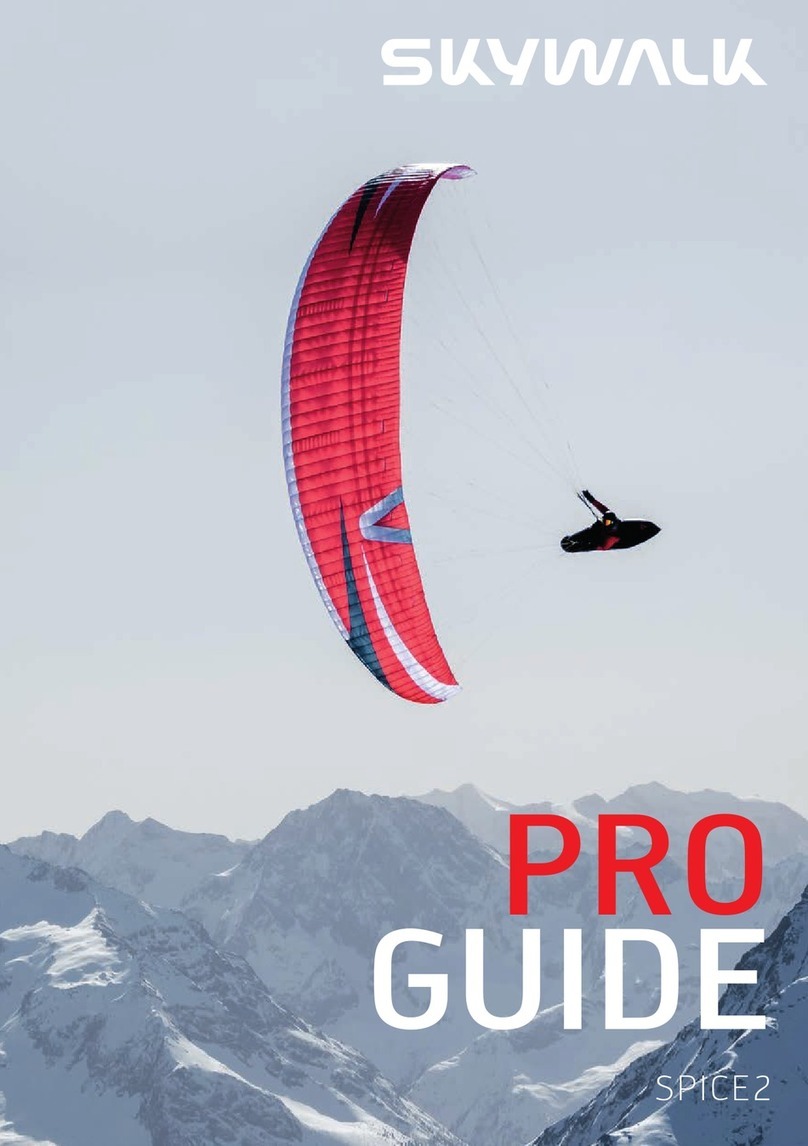
Eiri KY PIK-20 E Technical specifications

PIK-20
E
Flight
manual
FLIGHT
MANUAL
for
ELF-LAUNCHING
AILPLANE
PIK-20
E
V
EIRI
KY
J
Kisällinkatu
8
F-15170
Lahti
17

ILMAILUHALLITU
Lentotu.vallisuusosasto
N:0
......................................

PIK-20
E
Flight
manual
A
FLIGHT
MANUAL
for
ELF-LAUNCHING
AILPLANE
PIK-20
E
SERIAL
NO:
REGISTRATION:
This
sailplane
must
be
operated
in
omplian e
with
this
Manual.
THIS
MANUAL
MUST
BE
KEPT
IN
THE
SAILPLANE
AT
ALL
TIMES.
Approved
by
National
Board
of
Aviation,
Finland
EIRI
KY
y
Kisällinkatu
8
F-15170
Lahti
17
page
i
EDITION
2
JANUARY
1980
ENGLI H

PIK
-20
E
Flight
manual
------------------------------------
x
I
FLIGHT
MANUAL
Page
TABLE
OF
CONTENTS
1.
TECHNICAL
DATA
1-1
1.1
Main
te hni al
data
I-
1
1.2
Wing
I-
1
1.3
Horizontal
stabilizer
and
elevator
1-2
1.4
Verti al
stabilizer
and
rudder
I-
2
1.5
Fuselage
I-
2
1.6
Engine
1-
3
1.7
Propeller
I-
3
1.8
Weights
and
loads
1-3
2.
SAILPLANE
DESCRIPTION
I-
3
2.1
General
des ription
I-
3
2.2
Flight
ontrol
and
flap
system
I-
4
2.3
Dive
brake
ontrol
I-
4
2.4
Engine
ontrols
I-
5
2.5
Engine
retra ting
system
I-
5
2.6
Landing
gear
ontrol
I-
5
2.7
Other
ontrols
I-
5
2.8
Fuel
system
I-
6
2.9
Ele tri al
system
I-
6
2.10
Water
ballast
system
I-
6
3.
LIMITATIONS
I-
8
3.1
Airspeed
limits
I-
8
3.2
Flight
load
fa tors
I-
9
3.3
Operating
limits
I-
9
3.4
Weight
and
C.
of
G.
limits
1-10
3.5
Rated
load
in
aero
tow
1-10
3.6
Powerplant
limitations
1-10
3.7
Maximum
rosswind
1-10
4.
MARKINGS
1-11
4.1
Pla ards
1-11
EIRI
KY
---------------------------------------------------------
'
Kisällinkatu
8
F-15170
Lahti
17
page
ii

PIK
-20
E
Flight
manual
-----------------------------------
x
4.2
Symbols
of
the
Controls
1-13
4.3
Flight
Instrument
Markings
1-15
5.
NORMAL
PROCEDURES
1-17
5.1
Normal
pro edures he k
lists
1-17
5.2
Amplified
normal
pro edures,
general
I-23
5.3 Refueling
I-23
5.4
Water
ballast
filling
instru tions
I-23
5.5 Daily
he k
I-24
5.6 Before
starting
the
engine
I-24
5.7
Starting
the
engine
I-25
5.8
Warm-up
and
taxiing
I-25
5.9
Ground
test
I-26
5.10 Before
takeoff
I-26
5.11
Takeoff
I-26
5.12
Takeoff
in
aerotow
I-28
5.13
Takeoff
in
win htow
I-28
5.14
Climb
I-29
5.15 Cruising
I-29
5.16
Stopping
and
retra ting
the
engine
in
the
air
I-30
5.17
Glide
1-31
5.18 Restarting
the engine
in
the
air
1-31
5.19 Stalls
I-32
5.20
Approa h
and
landing
I-33
5.21
Stopping
the
engine
on
the
ground
I-34
5.22
Outlanding
I-34
5.23
Aerobati s
I-34
5.24 Cloud
flying
I-35
5.25
Flying
in
the
rain
I-35
5.26 Flying
in
i ing
and
low
temperature
onditions
I-36
5.27
Flying
at
high
altitudes
I-36
6.
WEIGHT
AND
BALANCE
I-37
6.1
Preflight
he k
I-37
6.2
Cal ulations
for
a tual
C.
of
G.
lo ation
I-39
EIRI
KY
____
___
y
Kisällinkatu
8
sf
-
15170
Lahti
17
page
Hi

PIK-20
E
Flight
manual
'x
6.3 Sample
Problem:
A tual
weight
and
C.
of
G.
in
flight
1-40
6.4
Weight
and
Balan e
Re ord
1-41
7.
PERFORMANCE
>
‘
42
7.1
Performan e
in
glide
with
engine
retra ted
I-42
7.2
Performan e
with
extended
powerplant
I-43
7.3
Use
of
flaps
1-49
7.4
M Cready
urves
l-
52
7.5
The
use
of
the
water
ballast
1-53
7.6
Pitot
stati
system
alibration
1-54
8.
EMERGENCY
PROCEDURES
1-55
8.1
Engine
failure
155
8.2
Fires
'-55
8.3
Jettisoning
the
anopy
1-56
8.4
Jumping
with
a
para hute
1-57
V
EIRI
KY
------------
---------------------------------------------
J
Kisällinkatu
8
F-15170
Lahti
17
page
iv

PIK-20
E
Flight
manual
A
LOG
OF
REVISION
Any
revision
of
the
present
Manual
must
be
re orded
in
the
following
table.
The
new
amended
text
in
the
revised
page
will
be
indi ated
by
a
bla k
verti al
line
in
the
left
hand
margin
and
the
Revision
No.
and
date
will
be
shown
on
the
bottom
of
the
page.
Rev.
No.
Revised
Pages
Des ription
of
Revision
Date
Signed
Edition
2
All
pages
New
Edition
(Repla es
previous
edition
dated
November
1978)
Rev.
1
I-6,
I-8,
1-13,
I-48
New
Fuel
tank.
S/N:s
20215,
20221
and
up
Jan
80
EIRI
Rev.
2
I-9,
1-11,
1-21,
I-28
Tow
hook
at
station
1850
for
win h-
and
aerotow
operation
S/N:s
20215,
20221
and
up
Jan
80
EIRI
Rev.
3
I-7
Assembly
of
starter
emergen y
relay
S/N:s
20213,
20214,
20217
and
up.
Jan
80
EIRI
Rev.
4
I-3,
I-6,
1-10
Change
in
water
tank
volume
S/N:s
20247
and
up
Jan
80
EIRI
EIRI
KY
------------
-----------------
'
Kisällinkatu
8
F-15170
Lahti
17
page
v

PIK-20
E
Flight
manual
FIG
1:
THREE
VIEW
PIK-20E
-5k-
references
for
the
^
control
surface
movements
V
EIRI
KY
_______
___________________________
y
Kisällinkatu
8
F-15170
Lahti
17
page
vi

PIK-20
E
Flight
manual
1.
TECHNICAL
DATA
1.1
Main
technical
data
—
Span
—
Lenght
—
Height
1.2
Wing
—
Wing
area
—
Aspe t
ratio
—
Dihedral
angle
—
Sweep-ba k
angle
(quarter hord
line)
—
Angle
of
in iden e
—
Root
hord
—
Mean
hord
—
Tip
hord
—
Mean
aerodynami
—
Root
profile
—
Tip
profile
—
Flap
area
15
m
(49.2
ft)
6.53
m
(21.4
ft)
1.47
m
(4.8
ft)
10.0
m
2
(107.6
sqft)
22.5
3°
1.36°
1
°
0.90
m
(2.95
ft)
0.65
m
(2.13
ft)
0.36
m
(1.18
ft)
(MAC)
0.70
m
(2.30
ft)
FX
67-K-170
FX
67-
K-
150
2
x
0.80
m
2
hord
—
Flap
movements
—
Aileron
movements
+
16°
flap
flap
root
46
±2.5
mm
16°
±
1°
down
aileron
root
30
±1.8
mm
0°
±1°
flap
root
0
±2.5
mm
aileron
root
0
±
1.8
mm
-12°
±1°
up
flap
root
35
±
2.5
mm
aileron
root
22.5
±
1.8
mm
flap
root
38,0
±5°mm
(13°.;.
2
‘
)up
aileron
root
O/l
+36
24,5
vs
mm
(12.5°.;.
2
‘
flap
root
36,0
*2
6
mm
(down
aileron
root
23,5
'umm
EIRI
KY
J
Kisällinkatu
8
F-15170
Lahti
17
page
1-1

PIK-20
E
Flight
manual
A
0°
flap
(12°
r
2
)up
flap
root
aileron
root
_
♦
5.0
35,0
2.5
mm
22,5
18
mm
(11°.*
r
2
)down
flap
root
aileron
root
_
.
*50
31.0
2
s
mm
21.0
i
s
mm
12°
flap
(11°.v")up
flap
root
32,0
*
2
5
6
°mm
aileron
root
21,0
*i
3
8
6
mm
(9,5°
V
2
(down
flap
root
27,0
*2
5
5°mm
aileron
root
18,0
*i
3
8
6
mm
1.3
Horizontal
stabilizer
and
elevator
—
Area
—
Span
—
Aspe t
ratio
—
Angle
of
in iden e
—
Profile
—
Elevator
movements
1.25
m
2
(13.45
sqft)
2.4
m
(7.87
ft)
4.6
-
2
°
FX
71-L-150/20
Up
and
down
20°
±
1°
(47
±2.5
mm)
1.4
Vertical
stabilizer
and
rudder
-
Area
1.02
m
z
(10.98
sqft)
-Height
1.2
m
(3.94
ft)
-Profile
FX
71-L-150/30
—
Rudder
movements
Right
and
left
33°
±2°
(179
±11
mm)
(Control
surfa e
movement
referen es,
see
three
view
on
page
vi.)
1.5
Fuselage
—
Height
at
the
o kpit
-
Width
—
Main
wheel
—
Tail
wheel
0.86
m
(2.62
ft)
0.60
m
(1.97
ft)
5.00-5
100
x
36
mm
(4.0
x
1.5
in)
EIRI
KY
V
Kisällinkatu
8
F-15170
Lahti
17
page
I-2

PIK-20
E
Flight
manual
A
1.6
Engine
—
Engine
Manufa turer:
Rotax
GmbH,
Gunskir hen,
Austria
—
Engine
Model:
Rotax
501
—
Engine
Type:
Retra table
air ooled
2-stroke
500
m
2- ylinder
engine
with
1:2
toothed
belt
transmission
to
the
propeller
—
Power
Rating:
31.7
kW
(43
hp)
at
6200
rpm
1.7
Propeller
—
Propeller
Manufa turer:
1.
Propellerwerk
Hoffman
GmbH,
Rosenheim,
Federal
Republik
of
Germany
2.
Lentokonekorjaamo
E
Pankkonen,
Järvenpää,
Finland
-
Propeller
Model:
1.
Ho
11*
127B
87
2.
EP
P127/87
—
Propeller
Diameter:
1270
mm
(50
in)
—
Propeller
Type:
2
blade,
wooden,
fixed
pit h
1.8
Weights
and
loads
—
Empty
weight
—
Gross
weight
—
Maximum
water
ballast
—
Wing
loading
2.
SAILPLANE
DESCRIPTION
2.1
General
description
The
PIK-20
E
is
a
single
seat
unlimited
15
m
lass
Utility
Category
sail
plane
with
self
laun hing
apability.
It
is
designed
in
a ordan e
with
OSTIV-
Airworthiness
Requirements
For
Sailplanes
1976
and
German
LFSM
issue
1975.
The
whole
sailplane
is
made
of
epoxy
resin
laminates.
The
shoulder
onfiguration
wing
and
the
ontrol
surfa es
are
of
rigid
sandwi h
stru -
EIRI
KY
-------
J
approx.
300
kg
(660
lbs)
470
kg
(1036
lbs)
80
kg
(176
lbs)
36.
.
.47
kg/m
2
(7.37.
.
.9.63
Ibs/sqft)
Kisällinkatu
8
F-15170
Lahti
17
page
1-3
Revision
4.21.1.-80

^PIK
-20
E
Flight
manual
------------------------------------
^
ture,
PVC-foam
between
epoxy
laminates.
The
wing
spar
aps
are
ma
de
of
arbon
fibre.
The
fuselage
is
made
of
epoxy
laminates
stiffened
with
seven
ribs
in
the
fuselage
and
two
in
the
fin.
The
o kpit
area
is
reinfor ed
with
a
double
bottom
and
two
arbon
fibre
beams.
The
engine
opening
is
stiffened
with
two
large
diameter
beams.
The
retra table
engine
is
situated
behind
the
wing
in
the
fuselage.
The
ret
ra table
main
landing
wheel
is
equipped
with
a
drum
brake.
The
stee
rable
tail
wheel
is
lo ated
under
the
verti al
stabilizer.
The
whole
trailing-edge
flap
(flaperon)
is
utilized
as
aileron
and
flap
ontrol.
Aileron
neutral
position
travels
with
flap
setting
up
12°
to
down
16°.
Flaps
may
be
used
to
improve
performan e
while
thermalling
and
gliding
and
during
landing
as
landing flaps.
The
"T"-
onfiguration
tail
unit
has
on
ventional
elevator
and
rudder
surfa es.
2.2
Flight
control
and
flap
system
The
primary
flight
ontrol
surfa es
(ailerons,
elevator
and
rudder)
are
onne ted
to
a
onventional
ontrol
sti k
and
rudder
pedal
arrange
ment.
The
elevator
trim
is
ontrolled
by
a
green
knob
lo ated
on
the
left
side
onsole.
It
is
onne ted
to
the
elevator
ontrol
system
by
a
spring.
The
trim
is
also
onne ted
to
the
flap
defle tion
so
that
you
have
to
trim
the
sailplane
only
on e
at
your
weight
to
fly
with
0°
flaps
at
100
km/h.
After
that
you
trim
the
sailplane
by
moving
the
flap
ontrol
arm,
and
you
will
then
automati ally
have
the
optimum
flap
defle tion
for
any
speed
(see
7.3.1).
The
positive
range
is
optimized
for
ir ling
and
the
negative
range
for
ruising.
For
landing,
the
sailplane
has
to
be
trim
med
on e
again.
The
bla k
trailing
edge
flaps
ontrol
arm
is
lo ated
to
the
left
of
pilot's
seat.
The
markings
for
flap
defle tion
are
on
the
side
panel.
Full
negati
ve
position
is
forward.
2.3
Dive
brake
control
The
blue
dive
brake
ontrol
is
situated
together
with
the
flap
ontrol
on
EIRI
ky
---------
---------------------------
J
Kisällinkatu
8
F-15170
Lahti
17
page
I
-4

PIK-20
E
Flight
manual
A
the
left
side
panel
of
the
pilot's
seat.
The
over enter
lo king
system
is
in
both
wings.
The
dive
brakes
are
losed
in
the
forward
position.
2.4
Engine
controls
Choke,
de ompression
and
throttle
are
situated
on
the
left
of
the
instru
ment
panel.
Below
them
are
the
fuses
for
alternator,
fuel
pump,
radio
and
other
instruments.
Next
to
the
throttle
is
the
start
button
and
below
it
swit hes
for
main
power,
ignition
and
fuel
pump.
2.5
Engine
retracting
system
The
powerplant
is
retra table
into
the
fuselage
through
a
1.4
m
(4.6
ft)
long
opening
whi h
is
losed
with
two
doors.
The
engine
retra ting
sys
tem
is
operated
with
a
rank
on
the
right
o kpit
wall.
Retra ting
needs
15
turns
and
is
balan ed
with
a
gas
spring.
Engine
doors,
propeller
bra
ke
and
engine
lo king
are
operated
with
the
same
lever
behind
retra
ting
rank
on
the
right
wall.
The
doors
are
losed
and
the
lo king
is
on
in
the
forward
position.
The
propeller
brake
is
on,
the
lo king
off
and
the
doors
open
in
the
rear
position.
2.6 Landing
gear
control
The
retra table
main
landing
gear
is
operated
by
means
of
lever
lo ated
on
the
right
side
of
the
o kpit.
It
is
lightened
by
a
spring.
In
the
forward
position
the
main
wheel
is
down
—
in
the
rear
position
up.
The
wheel
brake
handle
is
atta hed
to
the
ontrol
sti k.
2.7
Other
controls
The
yellow
tow
oupling
release
knob
is
lo ated
uppermost
on
the
left
side
auxiliary
panel.
The
tow
oupling
hook
is
lo ated
on
the
underside
of
the
fuselage
below
the
instrument
panel
or
below
the
fuel
tank.
Win h
tow
an
be
made
only
with
the
rear
tow
hook.
The
water
ballast
draining
knob
is
lo ated
just
under
the
release
knob.
The
forward
posi
tion
is
losed
—
the
rear
position
open.
The
ventilation
knob
is
lo ated
under
the
water
ballast
knob.
The
forward
position
is
losed
—
the
rear
position
open.
EIRI
KY
y
Kisällinkatu
8
F-15170
Lahti
17
page
1-5

PIK-20
E
Flight
manual
The
anopy
is
hinged
to
the
fuselage
nose
one
and
an
be
opened
by
pushing
the
both
white
levers
forward
at
both
sides
of
the
frame.
Jettisoning
o urs
by
pushing
the
anopy
levers
forward
and
by
pulling
the
red
knob
right
in
the
instrument
panel
and
lifting
the
anopy.
The
grey
oloured
pedal
adjustment
knob
is
lo ated
in
front
of
the
ontrol
sti k
on
the
right,
below
the
instrument
panel.
The
seat
ba k
ad
justment
knob
is
on
the
left
side
of
the
o kpit.
The
ne k
rest
,
if
fitted,
an
be
adjusted
by
lifting
the
support
rod
and
moving
the
ne k
rest
to
desired
position.
2.8
Fuel
system
The
29
litres
(7.7
gal
U.S.)
apa ity
fuel
tank
is
situated
behind
the
ba krest.
1
litre
(0,25
gal
U.S.)
of
unusable
fuel
is
in luded.
Filling
ope
ning
is
on
the
left
side
of
the
fuselage
between
the
rear
anopy
frame
and
wing.
The
fuel
tank
vent
is
in
the
ap
on
the
left
side
of
the
fusela
ge.
A umulated
water
and
sediment
an
be
drained
and
he ked
by
using
the
sampler
up
when
draining
the
fuel
tank
daily
prior
to
first
flight.
The
drain
valve
is
situated
on
the
left
side
of
the
fuselage.
The
in
line
fuel
filter
is
situated
after
the
fuel
o k
in
the
baggage
ompart
ment.
The
ele tri al
auxiliary
pump
is
situated
down
in
the
engine
om
partment.
The
engine
has
an
impulse
driven
primary
fuel
pump.
2.9
Electrical
system
PIK-20
E
is
equipped
with
12
V
ele tri al
system
onsisting
of
12
Ah
bat
tery
in
the
engine
ompartment
or
below
the
instrument
panel
and
an
alternator.
The
power
is
re tified
and
regularized
with
a
Tympanium-
type
re tifier.
The
engine
has
an
0.4
hp
ele tri al
starter.
2.10
Water
ballast
system
The
40
litre
nylon
reinfor ed
plasti
bags
are
filled
through
the
draining
hole
on
the
underside
of
the
fuselage
behind
the
geardoors.
Notel:
1
mis
the
maximum
filling
height
(distan e
from
the
funnel
to
the
wing).
Higher
pressure
than
this,
0.1
Bar
(kp/ m
2
),
an
ause
seri
ous
damages
to
the
wing.
No
pressurized
filling
system
is
allowed.
EIRI
KY
Kisällinkatu
8
F-15170
Lahti
17
page
I
-6
Revision
1.21.8.-79
Revision
4.21.1.-80

PIK-20
E
Flight
manual
FIG
2.1:
ELECTRICAL
SYSTEM
i
t//~l
V
EIRI
KY
_____
______
y
Kisällinkatu
8
F-15170
Lahti
17
page
1-7
Revision
3.21.8.-79

PIK-20
E
Flight
manual
FIG
2.2:
FUEL
SYSTEM
Carburettors
Fuel
return
line
Engine
fuel
pump
Fuel
pump
Fuel
filter
drive
line
Fuel
o k
Filler
opening
with
vent
ap
Fuel
quantity
gauge
Fuel
feed
line
Fuel
tank
Ele tri
fuel
pump
Finger
strainer
3.
LIMITATIONS
3.1
Airspeed
limits
(I.A. .)
Never ex eed
(V
NE
)
In
rough
air
(V
B
)x)
Maneuvering
(V
A
)
In
aerotow
(V
T
)
xx)
In
win h
tow
(V
w
)
xx)
With
engine extended
Extending
and
retra ting
the
engine
EIRI
KY
---------------
Kisällinkatu
8
F-15170
Lahti
17
280
km/h
(174
mph,
151
kts)
215
km/h
(135
mph,
116
kts)
190
km/h
(118
mph,
103
kts)
190
km/h
(118
mph,
103
kts)
125
km/h
(
78
mph,
67
kts)
195
km/h
(121
mph,
105
kts)
135
km/h
(
84
mph,
73
kts)
Revision
1.21.8.-79
page
I-8

PIK-20
E
Flight
manual
>v
x)
Rough
air
means
su h
movements
of
air
as
in
eg.
leewave
rotors,
thunder
louds,
visible
whirlwinds
or
when
overflying
mountain
rests,
xx)
Aerotow
and
win htow
are
allowed
only
if
the
original
tow
hook
kit
is
installed.
Win htow
is
allowed
only
with
the
tow
hook
at
rear
station
1850
mm
(72,8
in).
3.1.1
Maximum
airspeed
for
deflected
flaps
0
+
16
+
12
.
.
.
+
2
0
...
-
12
km/h
155
215 280
V
mph
96
134
174
kts
84
116
151
+
16
flap
defle tion
is
only
for
landing
and
for
takeoff
on
soft
fields.
Note!
All
the
speeds
given
in
this
manual
are
indi ated
airspeeds
(I.A.S.)
assuming
zero
instrument
error.
3.2
Flight
load
factors
—
Flap
setting
—
Maximum
positive
—
Maximum
negative
3.3
Operating
limits
—
Minimum
equipment
list:
airspeed
indi ator,
altimeter,
magneti
ompass,
ball
type
slip
indi ator,
ta hometer,
fuel
quantity
indi ator,
ylinder
head
temperature
indi ator,
safety
belts,
seat
ushion,
hour
meter
and
mirror
for
he king
the
propeller
position.
—
Cloud
flying,
provided
that
the
following
instruments
installed:
mini
mum
equipment
and
turn
and
slip
indi ator,
variometer.
—
Approved
aerobati s:
Looping,
stall
turn,
steep
turn,
lazy
eight,
handelle
and
spin.
Flap
defle tions
from
neutral
to
12°
up
allowed.
—
During
aerobati s
the
engine
must
be
retra ted.
+
16°
+
12°
...
-
12°
+
4
+
5,3
0
-2,65
EIRI
KY
J
Kisällinkatu
8
F-15170
Lahti
17
page
I-
9
Revision
2.21.8.-79

PIK-20
E
Flight
manual
A
—
No
snapped
figures
approved.
—
A elerometer
mandatory
for
aerobati s.
—
Aerobati
maneuvres
with
water
ballast
are
prohibited.
3.4
Weight
and
C.G.
limits
—
Empty
weight
—
Maximum
gross
weight
|
—
Maximum
water
ballast
—
Pilot
and
para hute
—
Maximum
balan e
weight
in
nose
—
Maximum
balan e
weight
fitted
to
the
tail
wheel
spring
—
Max.
load
in
luggage
ompartment
—
Max.
load
in
rear
battery
ompartment
at
station
3.73
m
55
approx.
300
kg
470
kg
80
kg
110
kg
10
kg
3
kg
15
kg
11
kg
—
Maximum
weight
of
nonlifting
parts
(take-off
weight
without
wings)
328
kg
—
C.G.
limits
aft
datum
minimum
2.267
m
maximum
2.443
m
(19.
.
.44
%
MAC)
Datum:
Verti al
plane
2.113
m
(83.19
in)
forward
of
the
tube
forward
surfa e.
(660
lbs)
(1036
lbs)
(176
lbs)
(120.
.
.240
lbs)
(22
lbs)
(6.6
lbs)
(33
lbs)
(24
lbs)
(723
lbs)
(89.25
in)
(96.18
in)
first
wing
fitting
3.5
Rated
load
in
tow
6000
N
(1320
lbs)
3.6
Powerplant
limitations
3.6.1
Rotational
speed
—
max
rpm
6800
—
max
ontinuous
rpm
6000
3.6.2
Cylinder
head
temperatures
—
max
temperature
250°
C
(480°F)
3.7.
Maximum
crosswind
is
10
kts.
EIRI
KY
-----------------------
----------------------------------
y
Kisällinkatu
8
F-15170
Lahti
17
page
1-10
Revision
4.21.1.-80

4.
MARKINGS
PIK-20
E
Flight
manual
4.1
Placards
4.1.1
In
full
view
of
the
pilot
Maximum
airspeed
In
alm
weather
(V
NE
)
In
rough
air
(V
B
)
Maneuvering
(V
A
)
In
aero
tow
(V
T
)
|
In
win h
tow
(V
w
)
With
engine extended
Extending/retra ting
the
engine
280
km/h
174
mph
151
kts
215km/h
134
mph
116
kts
190
km/h
118
mph
103
kts
190
km/h
118
mph
103
kts
125
km/h
78
mph
67
kts
195
km/h
121
mph
105
kts
135
km/h
84
mph
73
kts
Weights
Gross
weight
470
kg
(1036
lbs)
in luding
water
ballast.
If
the
pilot's
weight
with
the
para hute
is
below
70
kg
(154
lbs)
ballast
weight
must
be
installed
in
the
nose
(see
Flight
Manual
and
Weight
and
Balan e
Da
ta
Sheet).
Operational
limitations
This
sailplane
must
be
operated
in
omplian e
with
the
operating
limits
as
stated
in
the
form
of
markings,
pla ards
and
in
the
PIK-20
E
Flight
Manual.
All
aerobati
maneuvers
in luding
spins
must
be
a omplished
in
a ordan e
with
the
PIK-20
E
Flight
Manual.
NO
SMOKING.
4.1.2
In
full
view
of
the
pilot
Maximum
airspeed
with
defle ted
flaps
<Sf
+
16
+
12
.
.
.
+
2
o
km/h
155
215
280
V
mph
96
134 174
kts
84
116
151
EIRI
KY
__________________________________ y
Kisällinkatu
8
F-15170
Lahti
17
page
1-11
Revision
2.21.8.-79

PIK-20
E
Flight
manual
A
4.1.3
In
full
view
of
the
pilot
Pre-flight
he k
Loading
and
ballast
................................................. he ked
Barograph
(if
installed)
............................................
on
Para hute
................................................................
se ured
Seat
and
rudder
pedals
..........................................adjusted
Safety
bareness
......................................................
fastened
Canopy
....................................................................lo ked
Main
swit h
..............................................................
on
Engine
and
engine
gauges
.
...................................... tested
and
he ked
Flight
instruments
.................................................... he ked
Flaps
.........................................................................
set
Trim
.........................................................................
set
Airbrakes
.................................................................. losed
and
lo ked
Controls
....................................................................free
Choke
........................................................................
off
Fuel
o k
...............................
(in
tow:
off)
..............
on
Ele tri al
fuel
pump
.............
(in
tow:
off)
..............
on
Tow
rope
(in
tow)
....................................................
oupled
Before
landing
Engine
......................................................................
retra ted
Water
ballast
............................................................drained
Landing
gear
............................................................
down
Flaps
..........................................................................12°.
.
.16°
down
Trim
..........................................................................set
for
landing
4.1.4
Other
placards
Adja ent
to
tow
oupling
............
Above
the
main
wheel
................
Adja ent
to
stati
pressure
entry
on
fuselage
skin
...........................
Adja ent
to
oxygen
ontrol
valve
(if
installed)
.................................
On
fuselage
nose
(inside)
............
RATED
LOAD
6000
N
(1320
lbs)
2.5
bar
(35
psi)
STATIC
PRESSURE
KEEP
CLEAR
DURATION
TABLE
BALLAST
EIRI
KY
J
Kisällinkatu
8
F-15170
Lahti
17
page
1-12
Other manuals for PIK-20 E
1
Table of contents
Other Eiri KY Aircraft manuals
Popular Aircraft manuals by other brands

Freewing
Freewing Go 2.5 user guide

Cirrus
Cirrus SR22T Pilot operating handbook

Pelegrin
Pelegrin Tarragon Pilot's operating handbook and flight manual
GRAVITY
GRAVITY X rocket manual

Diamond Aircraft
Diamond Aircraft DV 20 E 2022 Airplane Maintenance Manual
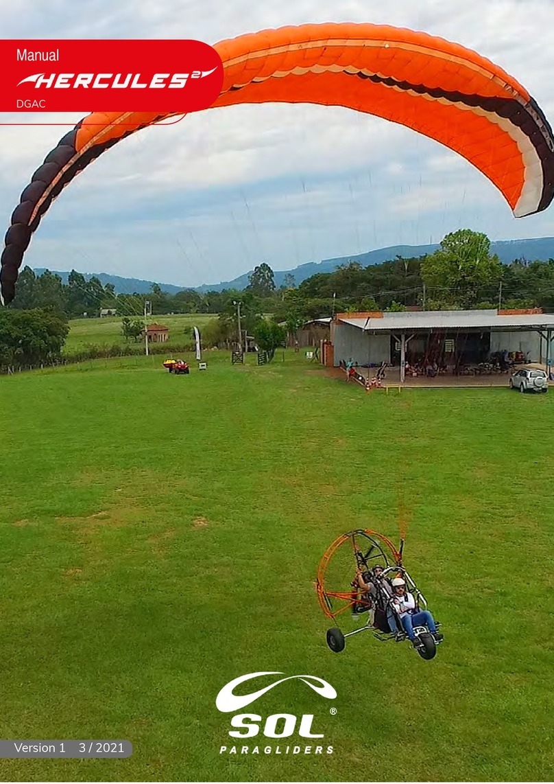
SOL paragliders
SOL paragliders Hercules 2 240 manual

