EIS 13503 Operating manual

Electrónica Integral de Sonido
EIS
Pupitre de llamadas
Intercom microphone base
USER AND INSTALLATION MANUAL
MANUAL DE USO E INSTALACION
2
12
E
ENG

EIS
2
1. Descripción general
Ø
Ø
Ø
Ø
Posibilidad de realizar llamadas
individuales, de grupo o
generales, así como llamadas a
un conjunto de zonas (función
"suma de zonas").
Selección de diversas
señales de "din-don" tanto
para indicar el inicio como
el final de un aviso.
Activación de las señales acústicas de alarma por teclado y desde
entrada externa
Ajuste por programa (sin de potenciómetros) de los niveles de
señal de micrófono, "din-don" y señales de alarma
...
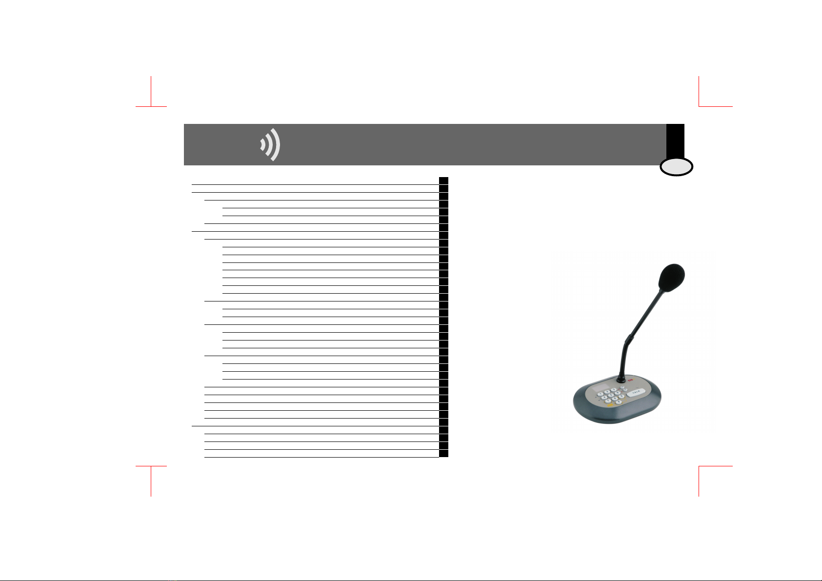
El pupitre 13503 ofrece la posibilidad de emitir avisos desde una
consola a cualquier zona de una instalación de Nueva Serie 100
ó Serie 400. Está destinado a instalaciones en comercios,
oficinas, salas de espera, etc.
Su versatilidad permite la instalación de uno o varios pupitres
combinada con uno o varios mandos. Dispone de generador de
señales acústicas, tanto para "din-don" de llamadas como para
señales de alarma.
Destaca por su diseño ergonómico y compacto
orientado sobre todo al usuario. De fácil manejo e
instalación, requiriere una mínima intervención por
parte del instalador eléctrico.
Este manual incluye las instrucciones de instala- ción y
manejo del pupitre. Entre las múltiples prestaciones
que ofrece cabe destacar:
E
1Descripción general 2
2Manual de instalación 3
2.1. Instalación con mandos de la Nueva Serie 100 3
2.1.1. Instalaciones de llamada general 3
2.1.2. Instalaciones de llamadas por zonas 3
2.2. Instalación con mandos de la Serie 400 3
3Manual de uso 4
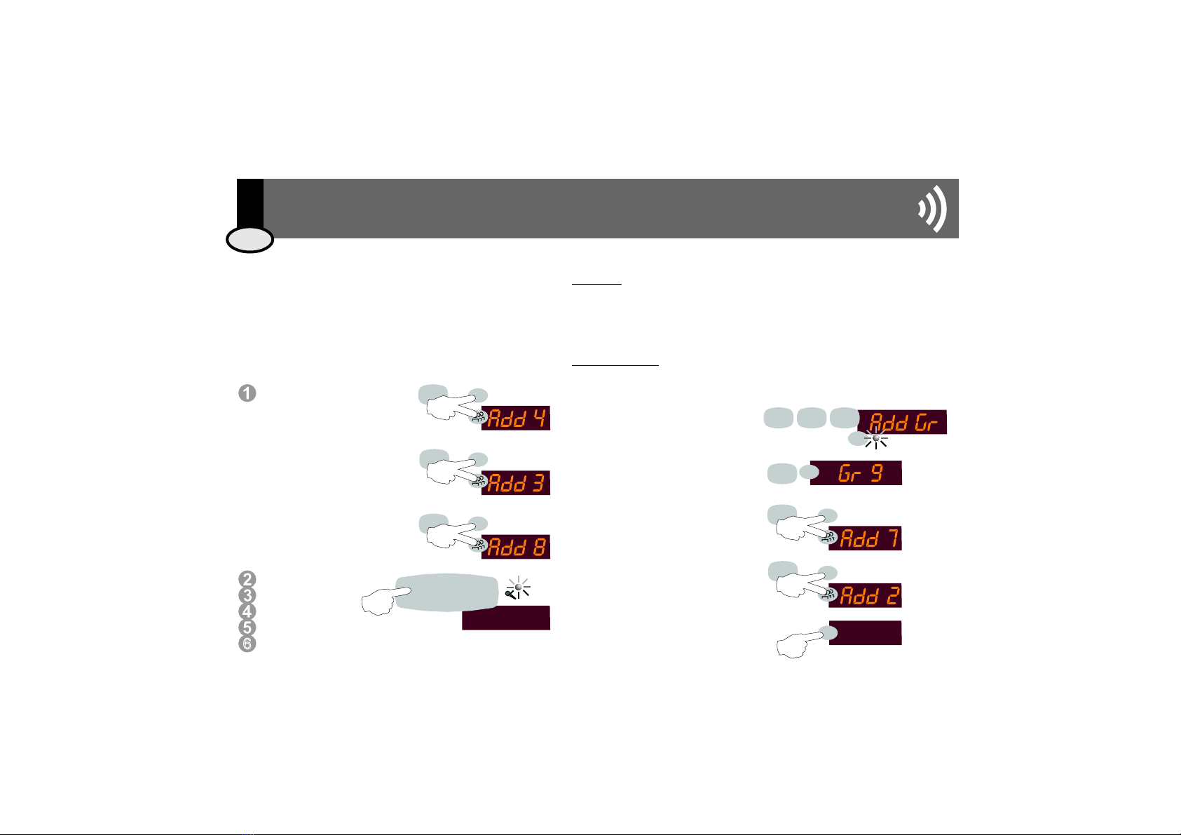
3.1. Realizar una llamada 4
3.1.1. Llamada general 4
3.1.2. Llamada individual 4
3.1.3. Llamada de grupo 4
3.1.4. Llamada a un conjunto de zonas: función "suma de zonas" (sólo Nueva Serie 100) 5
3.1.5. Programación de grupos 5
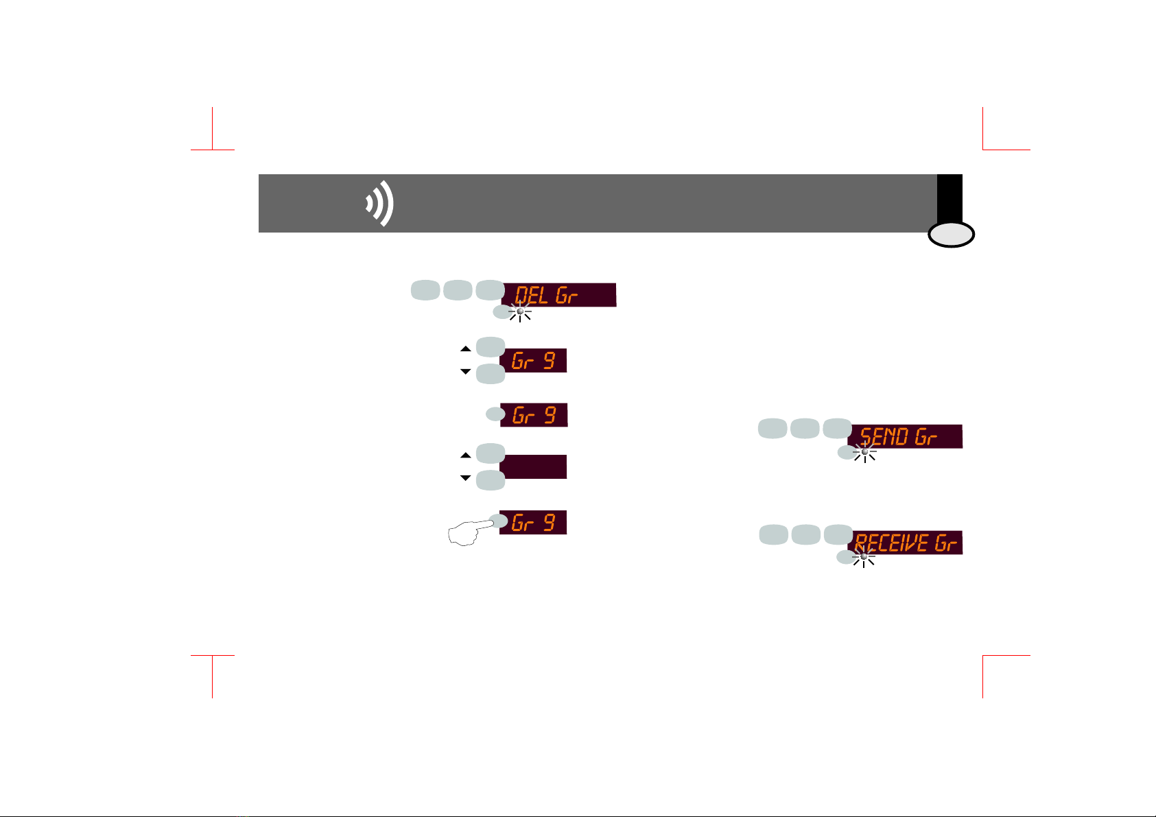
3.1.6. Borrado de grupos (sólo Nueva Serie 100) 6
3.1.7. Transferir la programación de grupos entre varios pupitres (sólo Nueva Serie 100) 6
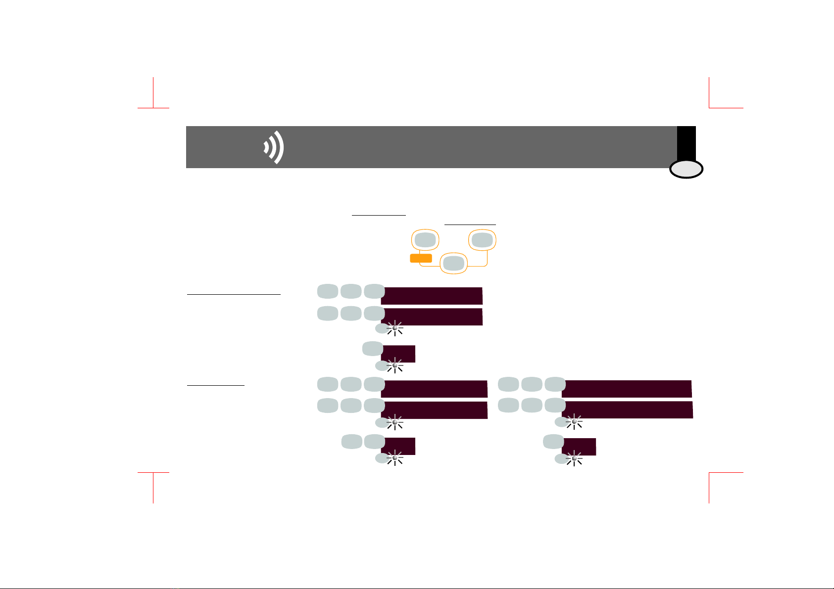
3.2. Ajustar el nivel de señal de micrófono 7
3.2.1. Opción de programación 7
3.2.2. Ajuste "on-line" 7
3.3. Selección de la señal de "din-don" 7
3.3.1. "din-don" inicial 7
3.3.2. "din-don" final 7
3.3.3. Ajuste del nivel de señal "din-don" 7
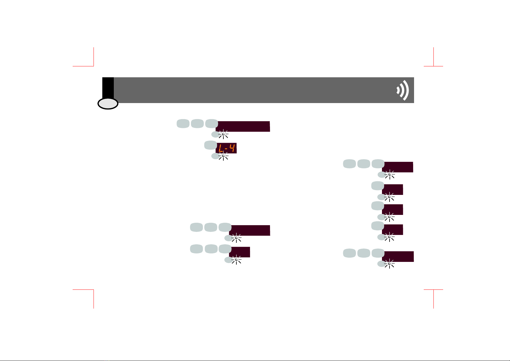
3.4. Generador de Alarmas 8
3.4.1. Alarma activable por teclado (tipo 1) y alarma activable por entrada externa (tipo 2) 8
3.4.2. Selección de las señales acústicas de alarma 8
3.4.3. Dirección de destino de las señales de alarma 8
3.5. Ajuste de la luminosidad del display 9
3.6. Asignación manual de la dirección de zona del Pupitre de Llamadas 13503 (sólo Serie 400) 9
3.7. Selección manual del tipo de instalación 9
3.8. Reset de fábrica 9
3.9 Guía rápida de programación 10
4Características técnicas 11
E100/1 Esquema de instalación Nueva Serie 100 22
E100/2 Esquema de instalación Nueva Serie 100 con extensión de zonas (2 canales) 23
E100/3 Esquema de instalación Nueva Serie 100 con extensión de zonas (4 canales) 24
E400 Esquema de instalación Serie 400 25

2. Manual de instalación
3EIS
2.1 Instalación con mandos de la Nueva Serie 100
2.2 Instalación con mandos de la
Serie 400
R
R
R
Ver esquema de conexionado E 100/1 para la instalación de un
pupitre 13503 con emisión de llamadas generales en
instalaciones de 2 o 4 canales. En ambos casos el conexionado es
idéntico, utilizando el módulo de conexión de línea 12701,
diferenciándose tan sólo en el conexionado de los canales de
música ambiental
Las instalaciones de 2 canales pueden realizarse con los mandos
32191 (2 canales) y 32196 (1 canal + sintonizador FM). Las de 4
canales con el mando 32195
Pueden coexistir en la misma instalación varios pupitres
conectados a uno o varios mandos
2.1.1. Instalaciones de llamada general 2.1.2. Instalaciones de llamadas por zonas
R
R
R
Para la emisión de avisos por zonas en instalaciones de 2 y 4 canales ver
esquemas E 100/2 y E 100/3 respectivamente. Observar que la
conexión del pupitre 13503 con el conector de línea 12701 y el módulo
de extensión de zonas 13504 es idéntica en ambos casos, variando tan
sólo el conexionado de los canales de música ambiental
En la Nueva Serie 100 el número de zona asignado a cada mando
viene definido por el cable que se conecta a su regleta 9. De esta forma,
la zona nº1 es la conectada al cable Z1, la zona nº2 es la conectada al
cable Z2, la nº8 al cable Z8, la nº14 al cable Z14, etc.
Pueden coexistir en la misma instalación varios pupitres conectados a
uno o varios mandos
La primera vez que se suministra alimentación
al pupitre 13503 debe definirse el tipo de
instalación al que está conectado: marcar 1
para Nueva Serie 100 (esquema E100/1),
marcar 2 para Nueva Serie 100 con extensión
de llamadas por zonas (esquemas E100/2 y
E100/3), marcar 3 para Serie 400 (esquema
E400. La opción escogida podrá cambiarse
siempre que se desee (ver 3.7).
En los esquemas se muestran sólo las conexiones en las que está implicado el
módulo de pupitre (13503) y el módulo de extensión de zonas (13504). Para ver
conexiones con otros elementos de la instalación ver CC-1003 Esquemas de
Conexiones
R
R
R
R
El pupitre de llamadas 13503 se conecta a mandos de la serie 400
(compactos o modulares) a través del módulo conector de línea 12701
tal y como se observa en el esquema E 400.
Alternativamente puede conectarse al módulo central 41491 o 41492
El número identificativo de zona es el definido para cada mando. Por
su parte, el número identificativo del pupitre se programa en el mismo
pupitre (ver 3.6)
Pueden coexistir en la misma instalación varios pupitres conectados a
uno o varios mandos
E
SERIE
2
3
1
PRG
PRG
PRG
2
1
3

3.1.1. Llamada general 3.1.2. Llamada individual 3.1.3. Llamada de grupo
Una llamada general es un aviso a la
dirección nº 0, la cual será recibida
por todos los mandos de la
instalación (excepto los que tengan
activada la función "no molesten")
Mantener pulsada la tecla TALK. La operación de llamada se mantendrá mientras se mantenga
pulsada esta tecla, y finalizará cuando se libere la misma
Mientras se genera la señal "din-don" de inicio el led de llamada se mantendrá en ROJO
Si existe alguna incidencia por la que no se ha podido iniciar la llamada (por ejemplo, el canal
de avisos está ocupado en ese momento, no existe el número de zona al que va dirigido el
mensaje, etc.) en el display aparecerá la indicación de ERROR.
Cuando el led de llamada se activa en VERDE, puede comenzarse a hablar. El micrófono y el
canal de avisos se mantendrán abiertos mientras se mantenga pulsada la tecla TALK
Al liberar la tecla TALK se genera la señal "din-don final" y posteriormente finaliza la operación
Marcar la
dirección 0
Una llamada individual es un aviso que será
recibido por una única zona. La selección de
la misma se realiza utilizando para ello su
"dirección individual de zona".
Esta operación no es posible en instalaciones
de Nueva Serie 100 que sólo admitan
llamada general (ver 2.1.1)
Una llamada de grupo es un aviso que será recibido por un
grupo de zonas. La selección del mismo se realiza
utilizando para ello su "dirección de grupo".
Esta operación no es posible en instalaciones de Nueva
Serie 100 que sólo admitan llamada general (ver 2.1.1). En
el resto los grupos se definen en la opción correspondiente
de programación (ver 3.1.5)
Marcar la
dirección de
zona (por ejemplo,
zona 48)
Marcar la dirección de grupo (por
ejemplo, grupo 3) seguida de la
tecla de GRUPO. El led
correspondiente quedará activado
T A L K
6
T A L K
T A L K
0
8
43
EIS
4
3. Manual de uso
3.1. Realizar una llamada
(rojo)
(rojo)
(verde)
E

2 - 7
3.1.5. Programación de grupos
3.1.4. Llamada a un conjunto de zonas:
función "suma de zonas"
(sólo Nueva Serie 100)
Serie 400
Nueva Serie 100
En instalaciones de Serie 400, cada mando tiene la posibilidad de tener asignado
uno o varios códigos de grupo. Para ello deben definirse en los propios mandos
en sus correspondientes Menús de Configuración e Instalación según el modelo
(ver CC-1023 Manual de Uso e Instalación de la Serie 400)
En instalaciones de Nueva Serie 100 que admitan llamadas por zonas (ver
2.1.2) la definición de grupos de zonas debe hacerse en el mismo pupitre. Se
admite un máximo de 10 grupos
de 10 zonas cada uno
Para crear un grupo pulsar 921
seguida de la tecla PRG
Seleccionar un grupo ertre 1 y 10
(por ejemplo 9) y pulsar la tecla PRG
Seleccionar el número de zona que se
desea añadir al grupo (por ejemplo,
zona 7). Para confirmar mantener
pulsadas las teclas PRG y GRUPO
durante 1sg
Repetir el proceso tantas veces como
zonas se quieran añadir hasta un
máximo de 10
Para grabar la programación,
mantener pulsada PRG durante 1sg
En instalaciones de Nueva Serie 100 que admitan llamadas
individuales (ver 2.1.2) puede realizarse llamadas a un conjunto
de zonas. A diferencia de la llamada de grupo, esta operación
NO ALMACENA EN MEMORIA el conjunto de zonas al que se
realiza la llamada
Marcar la dirección de
zona (por ejemplo, zona 4)
Para añadir nuevas zonas,
mantener pulsadas
simultáneamente las teclas
PRG y GRUPO durante 1sg.
Marcar otra dirección de zona
(por ejemplo, zona 3)
Repetir el proceso tantas veces
como zonas se quieran añadir
hasta un máximo de 10
Seguir el mismo
procedimiento de
manejo de la tecla
TALK descrito en el
resto de operaciones de llamada
descrito en los apartados 3.1.1, 3.1.2 y 3.1.3
3
8
4
PRG
PRG
PRG
1s
1s
1s
9
PRG
7
PRG
1s
2
PRG
1s
6
921
PRG
1s
EIS
53. Manual de uso
3.1. Realizar una llamada
PRG
PRG
3 - 4 - 8
T A L K
E

EIS
6
3. Manual de uso
on
3.1.6. Borrado de grupos (sólo Nueva Serie 100) 3.1.7. Transferir la programación de grupos
entre varios pupitres
(sólo Nueva Serie 100)
Para borrar un grupo pulsar
922 seguida de la tecla PRG
Con las teclas INC y DEC nos
movemos entre todos los grupos
definidos hasta el momento.
Para borrar todos ellos
seleccionar la opción ALL. Para
borrar sólo uno, seleccionar el
grupo deseado (por ejemplo, el
grupo número 9)
Pulsar PRG
Con las teclas INC y DEC nos
movemos entre la confirmación
(ON) o cancelación (OFF) del
proceso de borrado. Si estamos
seguros que deseamos borrar
este grupo, seleccionar la
opción ON manteniendo
pulsada la tecla PRG durante
1sg
En instalaciones de Nueva Serie 100 con extensión de zonas (ver
2.1.2) donde coexistan varios pupitres, la programación de los
grupos puede transferirse de un pupitre a otro evitando así tener que
repetir el proceso de grabación de los grupos en todos los pupitres.
Para ello, previamente debe haberse grabado la programación de
grupos (ver 3.1.5) en un pupitre cualquiera.
En dicho pupitre,
activar la opción 932
seguida de la tecla
PRG. Este pupitre
queda en modo de
TRANSMISION durante
1 minuto.
Seguidamente, para
cada uno de los
pupitres restantes ativar
el modo de
RECEPCION, pulsando
931 seguida de la tecla
PRG.
Cuando finaliza la recepción de datos se indica el número de grupos
recibidos, o bien una indicación de ERROR si el proceso no se ha
completado satisfactoriamente.
PRG
9
9
9
22
2
1s
1
4
1
4
PRG
3
31
3.1. Realizar una llamada
PRG
PRG
PRG
PRG
PRG
PRG
E

73. Manual de uso
3.3. Selección de la señal "din-don"
El pupitre tiene la posibilidad de generar una señal acústica indicativa del comienzo
de un aviso (din-don de inicio) y otra para indicar la finalización del mismo (din-don
final)
Pulsar 902 seguida de la
tecla PRG
Definir el tipo de señal acústica
(0=ninguna, 1, 2, 3)
Pulsar PRG para confirmar
Pulsar 901 seguida de la tecla
PRG
Marcar el nivel deseado entre los
valores 0 (mínimo) y 50 (máximo)
Pulsar PRG para confirmar
Pulsar 903 seguida de la
tecla PRG
Definir el tipo de señal acústica
(0=ninguna, 1, 2, 3)
Pulsar PRG para confirmar
FIRST TONE
2
9
2
2
0
END TONE
2
9
2
3
0
TONE LEVEL
29
9
9
2
0
1
3.2. Ajustar el nivel de señal de
micrófono
Existen dos maneras alternativas de ajustar el nivel de señal de
micrófono con el que el pupitre emitirá los avisos a los mandos
conectados a la instalación
Pulsar 911 seguida
de la tecla PRG
Marcar el nivel
deseado entre los
valores 0 (mínimo) y
99 (máximo)
Pulsar PRG para confirmar
Mientras se está realizando una
operación de llamada (ver
3.1.1, 3.1.2, 3.1.3) puede
ajustarse el nivel de salida de
señal de micrófono con las teclas
INC y DEC a la vez que se está
transmitiendo el mensaje hablado.
Una vez finalizado el mensaje, el nivel de emisión de
avisos quedará grabado en la memoria de
programación del pupitre
MIC LEVEL
52
59
911
2
5
1
4
3.2.1. Opción de programación
3.3.1. "din-don" inicial
3.3.2. "din-don" final
3.3.3. Ajuste del nivel de
señal "din-don"
3.2.2. Ajuste "on-line"
EIS
PRG
PRG
PRG
PRG
PRG
PRG
PRG
PRG
PRG
PRG
PRG
PRG
PRG
PRG
PRG
PRG
E

EIS 8
3. Manual de uso
3.4. Generador de Alarmas
3.4.1. Alarma activable por teclado (tipo 1) y alarma activable por entrada externa (tipo 2)
3.4.3. Dirección de destino de las
señales de alarma (sólo Serie 400)
El pupitre tiene la posibilidad de actuar como elemento generador de una señal acústica de
alarma que se transmitirá a toda la instalación o a los grupos de seleccionadas para ello.
Distingue dos tipos diferenciados de alarma: la se activa en el mismo teclado
del pupitre, manteniendo pulsadas simultáneamente las teclas 7, 9 y 0; la se
activa a través de una señal externa conectada como se
aprecia en los esquemas de conexión (2.1.2 para instalaciones
de la Nueva Serie 100 y 2.2 para instalaciones de la Serie 400)
alarma tipo 1
alarma tipo 2
En ambos casos el pupitre genera una señal
acústica característica para cada tipo de alarma
(ver 3.4.2) y la enviará a la dirección de grupo
progamada (ver 3.4.3). Por defecto la señal de
alarma se envía a todos los mandos como si fuera
una llamada general (dirección = 0).
En cualquiera de los dos casos el estado de
alarma finaliza al pulsar la tecla TALK
0
9
7
Alarm
Tipos de señales acústica
Ajuste del nivel
Para seleccionar la señal acústica
indicativa de la alarma tipo 1 ó 2
pulsar respectivamente 942 ó 945
seguida de la tecla PRG
Definir el tipo de señal acústica (1, 2, 3) o
marcar 0 para desabilitar el tipo de alarma 1
Pulsar PRG para confirmar
Para ajustar el nivel de la señal
acústica de alarma tipo 1 ó 2 pulsar
respectivamente 941 ó 944 seguida
de la tecla PRG.
Marcar el nivel deseado entre los valores 0
(mínimo) y 50 (máximo)
Pulsar PRG para confirmar
Para seleccionar la dirección a la que va dirigida la señal
de alarma tipo 1 ó 2 pulsar respectivamente 943 ó 946
seguida de la tecla PRG.
Definir el número de grupo (entre 0 y 250 para la Serie
400 y entre 0 y 10 para la Nueva Serie 100) a la cual irá
dirigida la señal de alarma.
Si se desea que la alarma vaya dirigida a todas las zonas,
marcar dirección 0
ALARM 1 TONE
ALARM 2 TONE
A- 1
9
9
2
4
4
1
5
3.4.2. Selección de las señales acústicas
de alarma
Pulsar PRG
para
confirmar
PRG
PRG
PRG
PRG
4
4
ALARM 1 LEVEL
ALARM 2 LEVEL
9
9
1
4
PRG
PRG
29
9
2
PRG
PRG
ALARM 1 ADDRESS
ALARM 2 address
9
9
4
4
3
6
PRG
PRG
0
0
PRG
PRG
E

EIS3.7. Selección manual del tipo de
instalación
La primera vez que se suministra alimentación al pupitre debe
definirse el tipo de instalación donde está conectado, esto es:
instalación de Serie 400, Nueva Serie 100 o Nueva Serie 100
con extensión de llamadas. Posteriormente puede cambiarse
manualmente este tipo de instalación:
SERIE
1
2
3
9
2
14
3.5. Ajuste de la luminosidad del display
Pulsar 912 seguida de la
tecla PRG
Definir el nivel de señal luminosa del
display entre los valores 1(mínimo),
2(medio), 3(alto) y 4 (máximo) y pulsar
PRG para confirmar
En la Serie 400 todos y cada uno de los dispositivos instalados se identifican por
una dirección de zona que debe ser única para cada uno de ellos y con un valor
comprendido entre 1 y 250 (ver CC-1023 Manual de Uso e Instalación Serie 400)
Cada vez que el pupitre se conecta a una instalación éste realiza un proceso
automático de asignación dinámica de una dirección que no esté utilizada en ese
momento. Sin embargo, si el usuario desea cambiar esta dirección puede realizar
el siguiente procedimiento:
light level
92
1
4
3.6. Asignación manual
de la dirección de zona del Pupitre de
Llamadas 13503 (sólo Serie 400)
3.8. Reset de fábrica
Para realizar un reset de los
datos de programación y
volver a la configuración
con la que el pupitre sale de
fábrica pulsar la
combinación 951 y
posteriormente la tecla PRG
RESET
951
93. Manual de uso EIS
Pulsar 913 seguida de la tecla PRG
Definir una dirección entre los valores 1
y 250 (por ejemplo, 192) y pulsar la
tecla PRG.
Pulsar 914 seguida de PRG
Para instalaciones de Nueva Serie 100
con sólo llamada general (ver esquema
E100/1) pulsar 1 seguido de PRG
Para instalaciones de Nueva Serie 100
con llamadas por zonas (ver esquemas
E100/2 y E100/3) pulsar 2 seguido de
PRG
Para instalaciones de Serie 400 (ver
esquema E400) pulsar 3 seguido de PRG
En este momento el pupitre comprobará que dicha dirección está libre y, si es
así, la tomará como propia. Si por el contrario esa dirección ya estuviese
ocupada por otro elemento de la instalación (un mando, interface de PC u otro
pupitre) reiniciará el procedimiento
PRG
PRG
PRG
PRG
ADDRESS
192
9
92
1
1
3
PRG
PRG
PRG
PRG
PRG
PRG
PRG
PRG
PRG
PRG
PRG
PRG
PRG
PRG
E
1
3

EIS 10
3. Manual de uso
3.9. Guía rápida de programación
valor
de fábrica
display valor
mínimo
valor
máximo
valor
de fábrica
display valor
mínimo
valor
máximo
PRG
FIRST TONE
PRG
END TONE
PRG
TONE LEVEL
1
1
100
25 050
103
103
4
250
400
ADRESS 249
light level
PRG
PRG
PRG
PRG
PRG
PRG
PRG
MIC LEVEL
SERIE
50 099
4
2
3
1
2
2
2
3
1
1
1
0
0
0
1
2
2
1
3
3
1
9
9
9
9
9
9
9
9
9
9
103
103
02500
02500
ALARM 1 TONE
ALARM 2 TONE
ALARM 1 ADDRESS
ALARM 2 address
RESET
ALARM 1 LEVEL
ALARM 2 LEVEL
25 050
25 050
PRG
PRG
PRG
PRG
PRG
PRG
PRG
2
5
1
1
4
3
6
4
4
5
4
4
4
4
9
9
9
9
9
9
9
PRG
4
1
9
E

EIS
11
E
13503 MIN NORMAL MAX NOTAS
Dimensiones 160x110x38 mm exterior (ancho x alto x fondo)
275 mm longitud micrófono
Alimentación 14 15 16 Vdc regleta 2
Consumo 31 65 105 mA regleta 2
Banda de paso micrófono 100 10000 Hz
Señal de avisos 33,5 Veff regleta 7
Impedancia de salida señal avisos 30 100 ohms regleta 7
Control salida 013,6 Vdc regleta 9
Control entrada 3,8 29 Vdc regleta 9
Impedancia de entrada control 22000 ohms regleta 9
Longitud cable hasta 127x1 2m
13504 MIN NORMAL MAX NOTAS
Dimensiones 45x45x43 mm exterior (ancho x alto x fondo)
45x45x36 mm hueco (ancho x alto x fondo)
45x45 mm frontal (ancho x alto)
Alimentación 13 15 16 Vdc regleta 2
Consumo 10 mA regleta 2
Control entrada 55,6 Vdc regleta Zin
Control salida 5Vdc regleta Zout
11,9 12 12,8 Vdc regletas Z1 .. Z10
Impedancia salida control 100 ohm regletas Z1 .. Z10
Longitud cable hasta 127x1 15 m
Longitud cable hasta otro 13504 150 m
4. Características técnicas

EIS
12
1. General Description
Ø
Ø
Ø
Ø
Ability for individual, group or
general intercom transmission
as well as transmission to a
set of zones (zone
combination function).
Ability to select the
announcing tone, both
for first and end tone of
intercom transmission.
Ability to activate audio alarm
signal on the keypad and via external input.
Ability to use program (without the need of manual control
device) to adjust levels of microphone signal, announcing tone,
and alarm.
...
Intercom Microphone Base 13503 provides the ability to
generate intercom calls from a console to any zone of a New
100 Series or 400 Series installation. It was designed for use in
existing installations in stores, offices, waiting rooms, etc.
Its versatility allows for the installation of one or several bases
combined with one or several control units. It is equipped with
an audio signal generator for both announcing tones as well
as for alarm signals.
Ergonomic and compact in design, it is specifically
made to be user-friendly. It is extremely easy to use
and install, requiring minor electrical installation
work only.
This manual contains installation and user instructions
for the base. Some of its many features include:
ENG
1GeneralDescription12
2InstallationManual13
2.1.InstallationwiththeNew100SeriesControlUnits13
2.1.1.GeneralPagingInstallations13
2.1.2.IndividualPagingInstallations13
2.2.Installationwiththe400SeriesControlUnits13
3UserManual14
3.1.Tomakeanannouncement14
3.1.1.GeneralPaging14
3.1.2.IndividualPagingInstallations14
3.1.3.GroupPaging14
3.1.4.Pagingtoasetofzones:the“zonecombination”function(New100Seriesonly)15
3.1.5.GroupProgramming15
3.1.6.DeletingGroups(theNew100Seriesonly)16
3.1.7.TransferringGroupProg.toseveralIntercomMicrophoneBases(New100Seriesonly)16
3.2.AdjustingtheMicrophoneSignalLevel17
3.2.1.ProgrammingOption17
3.2.2.On-lineAdjustment17
3.3.AnnouncingToneSelection17
3.3.1.Firsttone17
3.3.2.Endtone17
3.3.3.AdjustingAnnouncingToneVolumeLevel17
3.4.AlarmGenerator18
3.4.1.AlarmActivatedbyKeypad(type1)andAlarmActivatedbyExternalOutput(type2)18
3.4.2.SelectingtheAlarm’sAudioSignal18
3.4.3.DestinationAddressofAlarmSignals18
3.5.AdjustingDisplayLightLevel19
3.6.ManualAssignmentofZoneAddressforIntercomMicrophoneBase13503(Series400only)19
3.7.ManualSelectionofInstallationType19
3.8.FactoryReset19
3.9ProgrammingQuickGuide20
4Technicalcharacteristics21
E100/1InstallationDiagramfortheNew100Series22
E100/2InstallationDiagramfortheNew100SerieswithZoneExtension(2channels)23
E100/3InstallationDiagramfortheNew100SerieswithZoneExtension(4channels)24
E400SeriesInstallationDiagram25

2. Installation Manual
13 EIS
2.1 Installation with the New 100 Series Control Units
2.2 Installation with the 400 Series
Control Units
R
R
R
Refer to E100/1 for the installation of a 13503 intercom
microphone base for general intercom transmission in 2 or 4
channel installations. The wiring is identical in both cases, using
12701 line connection devices. The only difference is the
connection of the background music channels.
Installation of 2 channels is possible with control units 32191 (2
channels) and 32196 (1 channel + FM tuner). Four-channel
installation is possible by using control unit 32195.
Several microphone bases connected to one or more control units
can coexist in a single installation.
2.1.1. General Paging Installations 2.1.2. Individual Paging Installations
R
R
R
For intercom transmission by zones in 2 and 4 channel installations
see E 100/2 and E 100/3 respectively. Note that connection of base
13503 with line connector 12701 and zone extension module 13504
is identical in both cases. The only difference is the connection of the
background music channels.
In the New 100 Series, the number of zone assigned to each control
unit is defined by the cable that is connected to its connection terminal
9 so that zone number 1 is connected to cable Z1, zone number 2 is
connected to cable Z2, number 8 to cable Z8, number 14 to cable
Z14, etc.
Several bases can coexist in a single installation by connecting to one
or more control units.
R
R
R
R
Line connection device 12701 is used to connect intercom microphone
base 13503 to 400 Series control units (compact and modular), as
shown in diagram E400.
Connection can also be made to central unit 41491 or 41492.
The identifying number of each zone is defined by each control unit.
The microphone base identifying number is programmed at the base
itself (see 3.6.).
Several bases can coexist in a single installation by connecting to one or
more control units.
ENG
SERIE
2
3
1
PRG
PRG
PRG
2
1
3
The first time that Base 13503 is powered must
be defined the type of installation to which it is
connected: key 1 for New 100 Series (diagrams
E100/1), key 2 for New 100 Series with call
extension (diagrams E100/2 and E100/3), key
3 for the 400 Series (diagram E400). The type
of installation can be manually changed (see
3.7).
The diagrams only show the connections involving the base device
(13503) and the zone extension device (13504). To view connections
with other elements of the installation see CC-1003 Wiring Diagrams.

3.1.1. General Paging 3.1.2. Individual Paging 3.1.3. Group Paging
General intercom transmission is
transmission to address #0 and
which will be received by all control
units in the installation (except those
having the “do not disturb” function
activated).
Press the TALK button. The transmission lasts as long as the key is pressed and ends when the
key is released.
During the first tone the transmission LED will be red.
In the event there is an issue that hampers transmission (for example, the intercom channel is
busy at that time, the zone number directed to receive the transmission does not exist, etc.) the
ERROR message will appear on the display.
When the transmission LED turns GREEN, you may begin to talk. The microphone and the
intercom channel will be open as long as the TALK button is pressed.
As soon as the TALK button is released, the end tone sounds and the operation concludes.
Key
address
#0
Individual intercom transmission is
transmission that will be received by a single
zone. To select this kind of transmission, use
that “individual zone address”.
This operation is not possible in New 100
Series installations as these only allow for
general intercom transmission (see 2.1.1.)
Group intercom transmission is transmission that will be
received by a group of zones. To select this kind of
transmission, use that particular “group address”.
This operation is not possible in New 100 Series
installations as these only allow for general intercom
transmission (see 2.1.1.). In all other cases, groups are
defined in the corresponding programming option (see
3.1.5.).
Key in the
zone address
(for example,
zone 48).
Key in the group address (for
example, group 3) and then press
the GROUP button. The
corresponding LED will be activated.
T A L K
6
T A L K
T A L K
0
8
43
EIS
14
3. User Manual
3.1. To make an announcement
(red)
(red)
(green)
ENG

2 - 7
3.1.5. Group Programming
3.1.4. Paging to a set of Zones: the “zone
combination” function
(the New 100 Series only)
The 400 Series
The New 100 Series
In 400 Series installations each control unit has the ability of having one or more
group codes assigned. The codes must be defined in each control unit's
Configuration and Installation Menu, depending on the model (see CC-1034
User and Installation Manual for the 400 Series).
In New 100 Series installations that have the zone transmission feature (see
2.1.2.), the definition of groups of zones takes place at the microphone base
itself. A maximum of 10 groups of 10
zones each is permitted.
To create a group, key in 921 followed
by the PRG button.
Select a group between 1 and 10 (for
example, 9) and press the PRG button.
Select the zone number you wish to add
to the group (for example, zone 7). To
confirm, keep the PRG and GROUP
buttons pressed for 1 second.
Repeat the process for as many times
as necessary to add the desired number
of zones, up to a maximum of 10.
To store the programming into memory,
keep the PRG button pressed for 1
second.
Intercom transmission to a set of zones is possible in New 100
Series installations that allow for individual intercom transmission
(see 2.1.2.). In contrast to group intercom transmission, this
operation DOES NOT STORE IN MEMORY the set of zones to
which the transmission is addressed.
Key in the zone address (for
example, zone 4).
To add new zones,
simultaneously press the PRG
and GROUP buttons for 1
second.
Key the other zone address (for
example, zone 3).
Repeat the process for as many
times as necessary in order to
add the number of zones
desired, up to a maximum of 10.
Follow the same procedure
of pressing the TALK
button as described
in the rest of the
transmission operations in sections
3.1.1., 3.1.2. and 3.1.3.
3
8
4
PRG
PRG
PRG
1s
1s
1s
9
PRG
7
PRG
1s
2
PRG
1s
6
921
PRG
1s
EIS
15
PRG
PRG
3 - 4 - 8
T A L K
ENG
3. User Manual
3.1. To make an announcement

EIS
16
on
3.1.6. Deleting Groups (the New 100 Series only) 3.1.7. Transferring Group Programming to
several Intercom Microphone Bases
(the New 100 Series only)
To delete a group, key 922
followed by pressing the PRG
button.
Use the INC and DEC buttons to
move between all the groups
defined to date. To delete them
all, select the ALL option. To
delete just one, select that group
(for example, group #9).
Press the PRG button.
Use the INC and DEC buttons to
move between confirming (ON)
or canceling (OFF) the
operation to delete. If you are
certain you wish to delete this
group, select the ON option
while pressing the PRG button
for 1 second.
In New 100 Series installations with zone extension (see 2.1.2.)
where several microphone bases coexist, group programming may
be transferred from one base to another, thus avoiding the need to
repeat the process of programming the groups into each
microphone base.
To proceed, make sure the groups have been previously
programmed (see 3.1.5.) into any one of the microphone bases.
At that microphone
base, key in option
932 followed by
pressing the PRG
button. The base then
goes into SEND mode
for 1 minute.
Next, activate RECEIVE
mode by keying in 931
followed by pressing the
PRG button.
When the receipt of data is complete, the number of groups received
is indicated unless the legend ERROR appears, indicating that the the
process has not been completed satisfactorily.
PRG
9
9
9
22
2
1s
1
4
1
4
PRG
3
31
PRG
PRG
PRG
PRG
PRG
PRG
ENG
3. User Manual
3.1. To make an announcement

17
3.3. Announcing Tone Selection
It is possible for the microphone base to issue an audio signal that indicates the
beginning of an intercom transmission (first tone) and another to indicate its end (end
tone).
Key 902 followed by pressing the PRG
button.
Define the type of audio signal
(0=none, 1, 2, 3).
Press the PRG button to confirm.
Key 901 followed by pressing
the PRG button.
Key the desired sound level
between the values of 0
(minimum) and 50 (maximum).
Press the PRG button to confirm.
Key 903 followed by pressing the
PRG button.
Define the type of audio signal
(0=none, 1, 2, 3).
Press the PRG button to confirm.
FIRST TONE
2
9
2
2
0
END TONE
2
9
2
3
0
TONE LEVEL
29
9
9
2
0
1
3.2. Adjusting the Microphone
Signal Level
There are two alternate ways to adjust the microphone signal
level used by the base to transmit to the control units connected
to the installation.
Key 911 followed by
pressing the PRG
button.
Key the desired level
between 0 (minimum)
and 99 (maximum).
Press the PRG button
to confirm.
The microphone's output level
signal can be adjusted while
intercom transmission is taking
place (see 3.1.1., 3.1.2., 3.1.3.)
by using the INC and DEC buttons
while the spoken message is being
transmitted.
Once the transmission concludes, the transmission level
will be saved into the program memory of the
microphone base.
MIC LEVEL
52
59
911
2
5
1
4
3.2.1. Programming Option
3.3.1. First tone
3.3.2. End tone
3.3.3. Adjusting Announcing
Tone Volume Level
3.2.2. On-line Adjustment
EIS
PRG
PRG
PRG
PRG
PRG
PRG
PRG
PRG
PRG
PRG
PRG
PRG
PRG
PRG
PRG
PRG
ENG
3. User Manual

EIS 18
3.4. Alarm Generator
3.4.1. Alarm Activated by Keypad (type 1) and Alarm Activated by External Output (type 2)
3.4.3. Destination Address of Alarm
Signals (only 400 Series)
The microphone base has the feature of providing an audio alarm signal that can be
transmitted throughout the whole installation or to selected groups only.
There are two different types of alarm: type 1 alarm is activated at the microphone base key
pad by simultaneously pressing keys 7, 9 and 0; type 2 alarm is activated by means of an
external signal connected as shown in the wiring diagrams
(2.1.2. for New 100 Series installations and 2.2. for 400
Series installations).
In both options the microphone base generates a
characteristic audio signal for each type of alarm
(see 3.4.2.) and sends it to the group address
programmed (see 3.4.3.). By default the alarm
signal is transmitted to all control units, as if it
were a general transmission (address=0).
In both cases, the alarm signal is terminated when
the TALK button is pressed.
0
9
7
Alarm
Types of audio signal tone
Adjusting the volume level
To select type 1 or 2 audio alarm
signal tone, key in 942 or 945
respectively followed by the PRG
button.
Define the type of audio signal (1, 2, 3) or key
in 0 to deactivate type 1 alarm.
Press the PRG button to confirm.
To adjust type 1 or 2 audio alarm
signal volume level, key in 941 or
944 respectively followed by the
PRG button.
Key the desired sound level between the
values of 0 (minimum) and 50 (maximum).
Press the PRG button to confirm.
To select the address to receive a type 1 or 2 alarm signal,
key in 943 or 946 respectively followed by pressing the
PRG button.
Define the group number (between 0 and 250) for the 400
Series and between 0 and 10 for the New 100 Series)
which is to receive the alarm signal.
To have all areas receive the alarm key in address 0.
ALARM 1 TONE
ALARM 2 TONE
A- 1
9
9
2
4
4
1
5
3.4.2. Selecting the Alarm's Audio Signal
Press the
PRG button
to confirm.
PRG
PRG
PRG
PRG
4
4
ALARM 1 LEVEL
ALARM 2 LEVEL
9
9
1
4
PRG
PRG
29
9
2
PRG
PRG
ALARM 1 ADDRESS
ALARM 2 address
9
9
4
4
3
6
PRG
PRG
0
0
PRG
PRG
ENG
3. User Manual

EIS3.7. Manual Selection of
Installation Type
The first time that the microphone base is powered must be
defined the type of installation to which it is connected: 400
Series, New 100 Series or New 100 Series with call extension.
In any event, there is an option to allow for the manual selection
of this type of installation:
3.5. Adjusting Display Light Level
Key 912 followed by pressing the
PRG button.
Define the display light level by choosing
a value between 1 (minimum), 2
(medium), 3 (high) and 4 (maximum)
and press the PRG button to confirm.
Each and every Series 400 device installed is identified by a zone address that must
be unique to each one and have a value between 1 and 250 (see CC-1034 The
400 Series User and Installation Manual).
Each time the microphone base is connected to an installation, it initiates the
automatic process of assigning an address that is not being used at the time.
However, if the user wishes, the address can be changed by following these steps:
light level
92
1
4
3.6. Manual Assignment of Zone Address for
Intercom Microphone Base 13503
(Series 400 only)
3.8. Factory Reset
To reset programmed data
and return to the
microphone base's factory
configuration, key 951
followed by pressing the
PRG button.
RESET
951
19 EIS
Key 913 followed by pressing the PRG
button.
Define an address between the values
of 1 and 250 (for example, 192) and
press the PRG button.tecla PRG.
Key 914 followed by
pressing the PRG button.
Key 1 and then PRG for the New 100
Series, only general call (see E100/1
diagram)
Key 2 and then PRG for the New 100
Series with zone extension (see E100/2
and E100/3 diagrams)
Key 3 and then PRG for the 400 Series
(see E400 diagram)
The microphone base will then verify whether or not the address is available
and, if so, will take it as its own. If, however, the address has already been
assigned to another element in the installation (a control unit, a PC interface or
another base), it will restart the process.
PRG
PRG
PRG
PRG
ADDRESS
192
9
92
1
1
3
PRG
PRG
PRG
PRG
PRG
PRG
ENG
3. User Manual
SERIE
1
2
3
9
2
14
PRG
PRG
PRG
PRG
PRG
PRG
PRG
PRG
1
3

EIS 20
3.9. Programming Quick Guide
factory
setting
display minimum
value
maximum
value
factory
setting
display minimum
value
maximum
value
PRG
FIRST TONE
PRG
END TONE
PRG
TONE LEVEL
1
1
100
25 050
103
103
4
250
400
ADRESS 249
light level
PRG
PRG
PRG
PRG
PRG
PRG
PRG
MIC LEVEL
SERIE
50 099
4
2
3
1
2
2
2
3
1
1
1
0
0
0
1
2
2
1
3
3
1
9
9
9
9
9
9
9
9
9
9
103
103
02500
02500
ALARM 1 TONE
ALARM 2 TONE
ALARM 1 ADDRESS
ALARM 2 address
RESET
ALARM 1 LEVEL
ALARM 2 LEVEL
25 050
25 050
PRG
PRG
PRG
PRG
PRG
PRG
PRG
2
5
1
1
4
3
6
4
4
5
4
4
4
4
9
9
9
9
9
9
9
PRG
4
1
9
ENG
3. User Manual
Table of contents
Languages: