Eisys iMove-F User manual
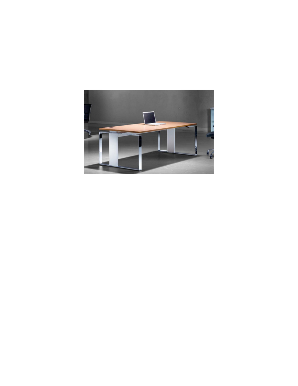
iMove-F Assembly Manual
(Motorized Version-M1/M2)
eisys, inc. 112 28th Street South • Birmingham, Alabama 35233 • 205.941.1942 • www.eisys-inc.com
eisysDESKING

Table of Contents
2
eisys, inc. 112 28th Street South • Birmingham, Alabama 35233 • 205.941.1942 • www.eisys-inc.com
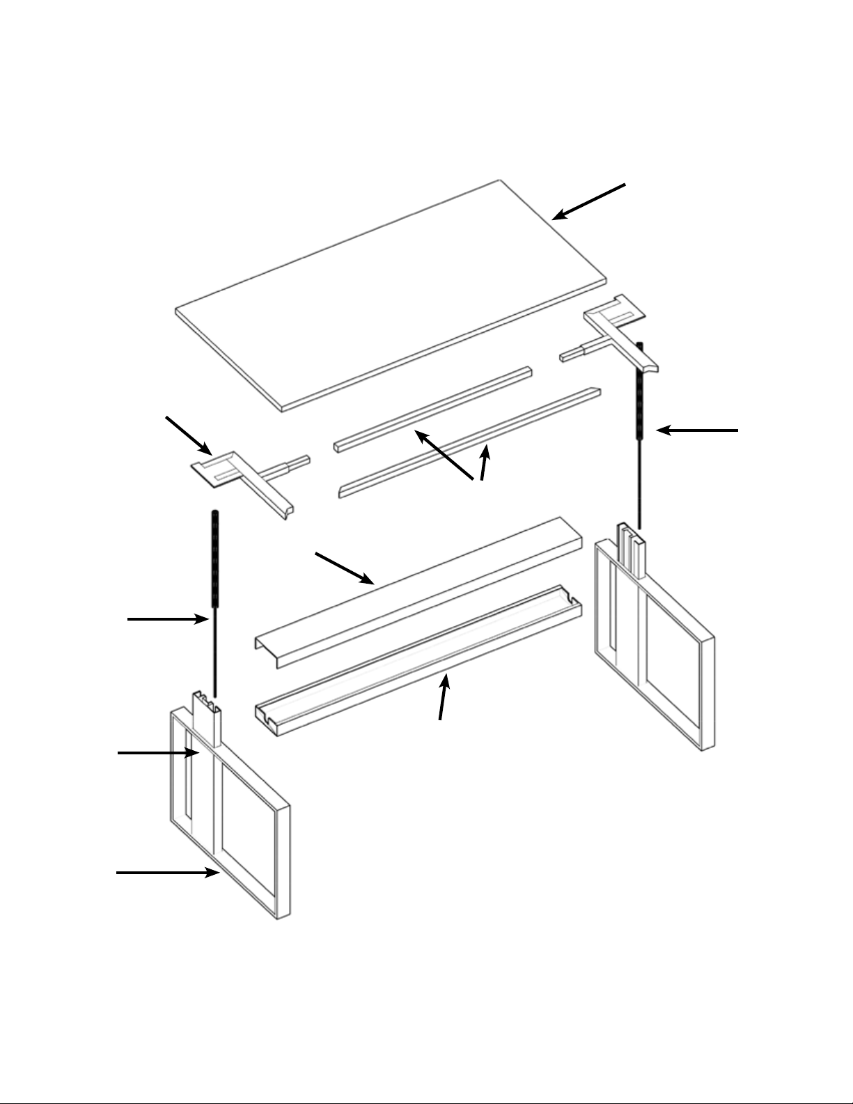
Exploded Desk Diagram
Hardward & Tools
Section 1: Basic Assembly of Desk
Shipped “KD” (knock down)
3
4
5
Section 2: Attaching the
Lowboard/Pedestal
Attaching Desk to Lowboard-
Pedestal
Section 3: Accessories
Section 4: Care & Maintenance
FAQ & Troubleshooting
Section 5: Contact Us
14
15
17
19
24
Unpack and Identify Parts
Assemble Cross Rail
to Columns
Connecting Desktop Supports
to Columns
Assemble Work Surface
Support Frame
Attach Work Surface to
Support Frame
Replace Cross Rail Cover
and Trim
Attach Control Panel
Leveling & Calibrating Desk
6
6
8
9
10
11
12
13
eisysDESKING
3
eisys, inc. 112 28th Street South • Birmingham, Alabama 35233 • 205.941.1942 • www.eisys-inc.com
Work Surface
Support Frame
Support Frame Spanners
Gas Cylinder
Gas Cylinder
Cross Rail Cover
Cross Rail
Leg
Foot
pic.1
eisysDESKING
4
eisys, inc. 112 28th Street South • Birmingham, Alabama 35233 • 205.941.1942 • www.eisys-inc.com
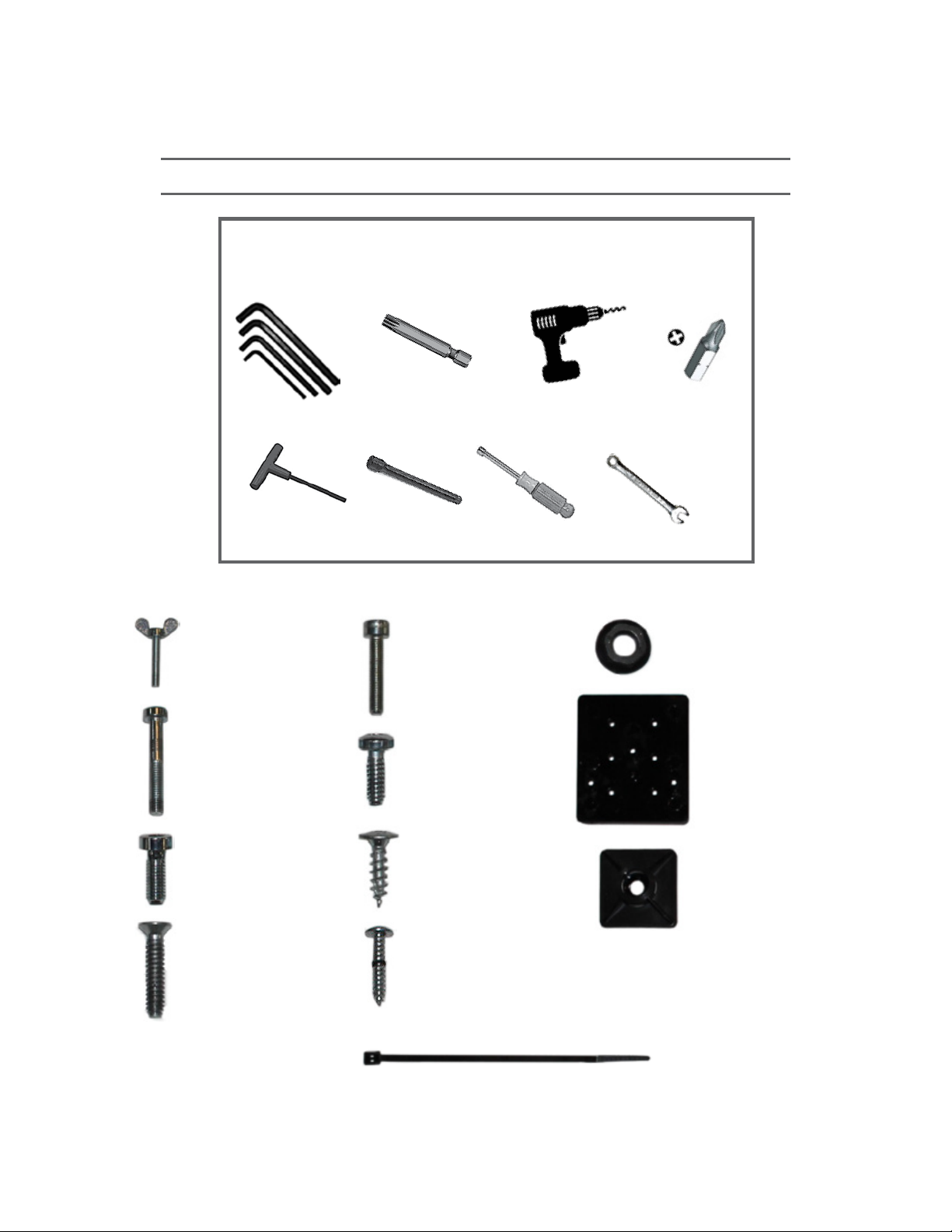
Tools and Hardware
Required and Recommended Tools
Metric Hex Wrenches
(3,4 & 5mm)
T25 Torx
Driver Bit
Cordless Driver
Drill
#1 Phillips
Driver Bit
6” 4mm T-Handle
Hex Driver
8” Driver
Extension
8mm Nut Driver or Box Wrench
Thumb Bolts—2 ea.
M6 x 1.0 x 40
Socket Cap Bolts—4 ea.
M6 x 1.0 x 16
Socket Cap Bolts—4 ea.
M5 x 25
Flat Head Screws—8 ea.
M5 x 20
Socket Cap Bolts—8 ea.
M5 x 16 TORX
Button Heads—8 ea.
20mm SPAX
Wood Screws—12 ea.
#4 x 16
Wood Screws—3 ea.
8mm Hex Nuts—8 ea.
4” Zip Ties—3ea.
Zip Tie Base—3ea.
Control Panel
Mounting Plate—1ea
eisysDESKING

5
eisys, inc. 112 28th Street South • Birmingham, Alabama 35233 • 205.941.1942 • www.eisys-inc.com
Section 1: Basic Assembly of Desk
Shipped “KD” (knock down)
-Motorized Version-M1/M2-
eisysDESKING
6
eisys, inc. 112 28th Street South • Birmingham, Alabama 35233 • 205.941.1942 • www.eisys-inc.com
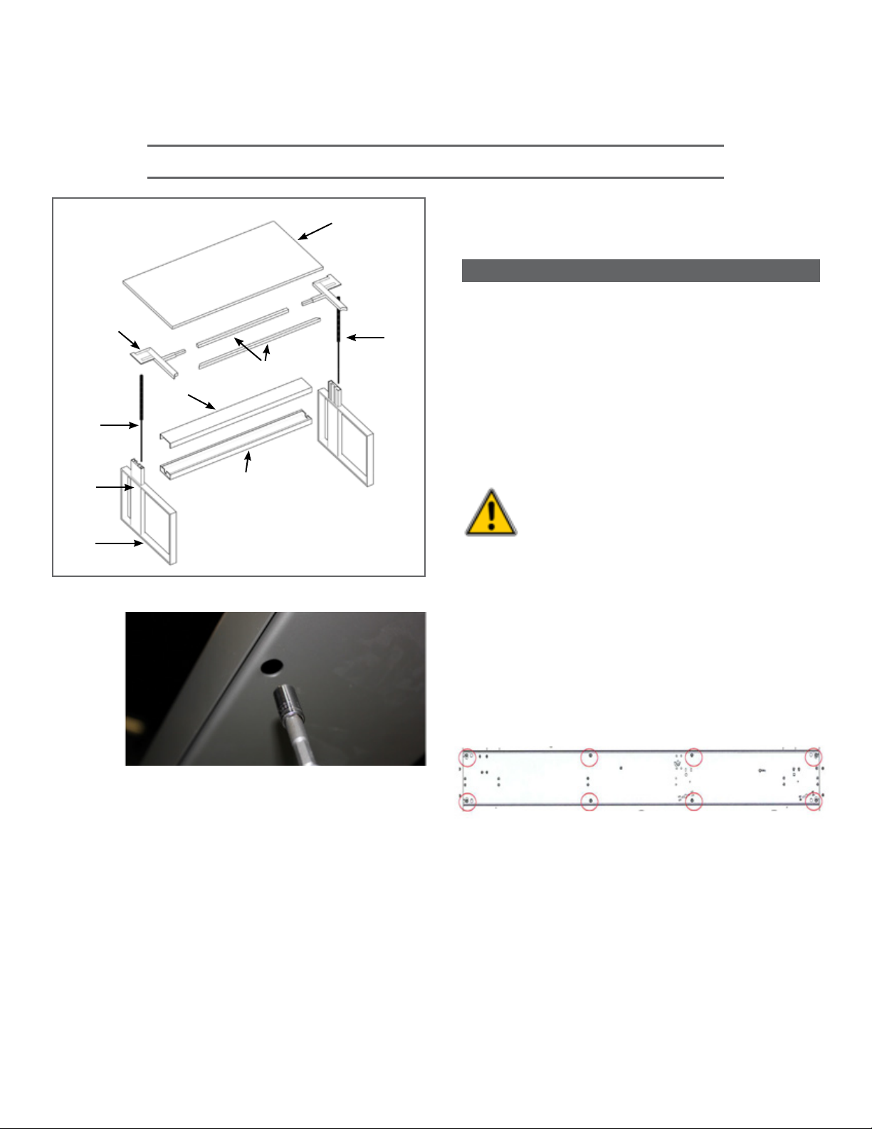
Basic Assembly of Desk Shipped “KD” (knock down)
Work Surface
Support Frame
Support Frame Spanners
Gas Cylinder
Gas Cylinder
Cross Rail Cover
Cross Rail
Leg
Foot
Use the 8mm nut driver or socket to remove
cross rail cover at indicated positions.
(pic.2-3 )
a.
pic.1
pic.2
cross rail as seen from below
pic.3
NOTE:
1.Not all desks will require two gas
cylinders. The number of gas cylinders will
depend on the size and weight of desk top.
2. If user is providing their own custom
top, determine the weight of the top and
contact eisys to order the appropriate
gas cylinders. (This step should have been
completed at order entry).
Use caution when working with
compressed gas cylinders.
An uncontrolled release could
cause severe damage and/or
personal injury.
1. Identify and uncrate ALL parts
(pic.1 )
2. Assembling Cross Rail to Columns (Legs)
eisysDESKING
7
eisys, inc. 112 28th Street South • Birmingham, Alabama 35233 • 205.941.1942 • www.eisys-inc.com
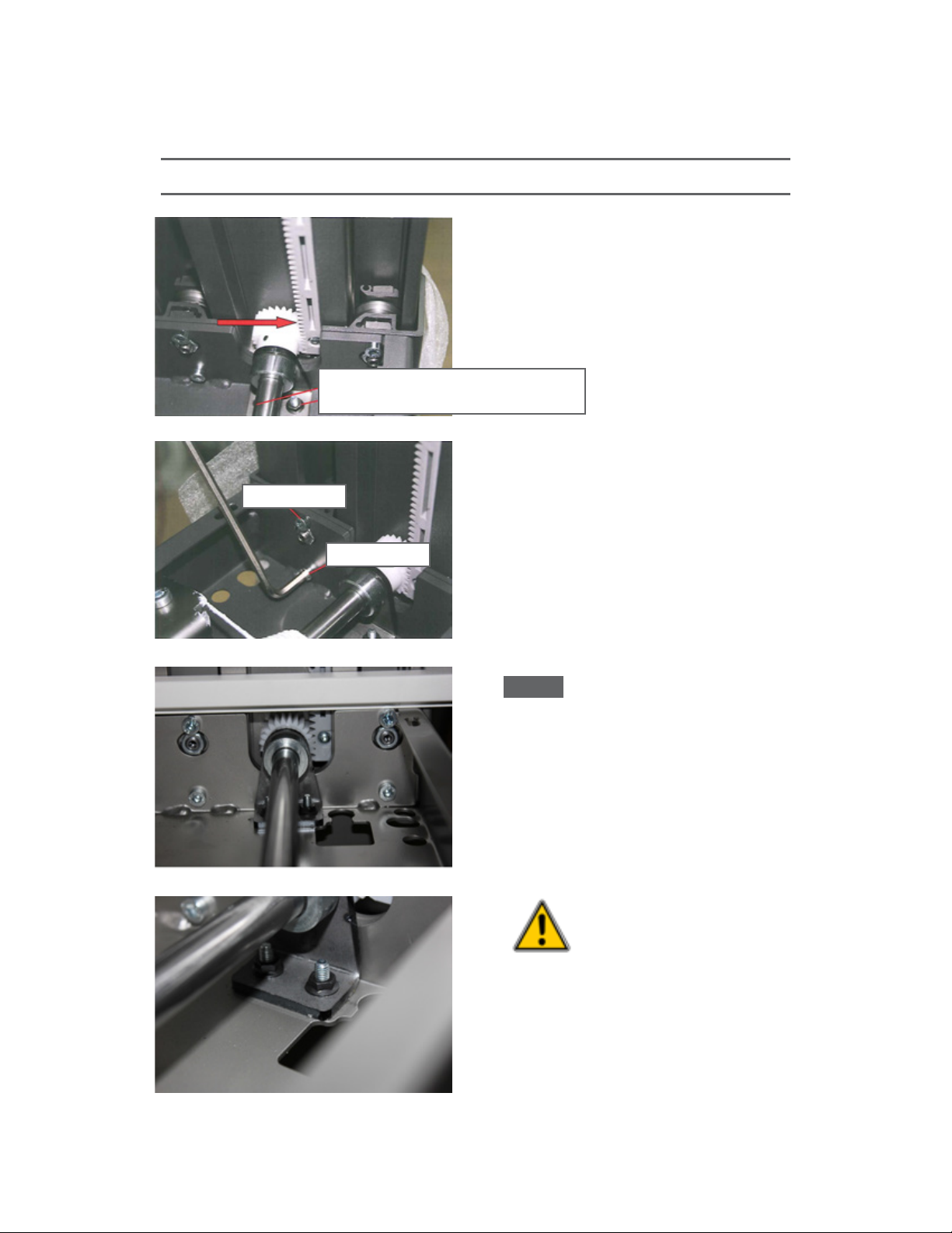
Using the 3mm & 8mm wrenches,
loosen/remove the two drive shaft support
bracket bolts at each end of cross rail.
(pic.5 & pic.6)
2.
With the “inner leg” FULLY extended join
the cross rail to the leg and carefully insert
the gear into the track. (pic.5) Make sure the
inner leg is FULLY extended and the gear is
properly engaged with the track.
*TIP: The screw head at the end of the
geared track should be aligned with the
approximate center of the drive shaft/gear
when the leg is at max height. (pic.7)
Once cross rail is secured to legs, make sure
the gear is seated with the geared track then
tighten shaft support bracket bolts. (pic.8)
d.
pic.5
pic.6
pic.7
screws for shaft support
screw from below cross rail
long bolt
short bolt
*TIP:
pic.8
Basic Assembly of Desk Shipped “KD” (knock down)
Assembling Cross Rail to Columns (Legs)
(continued)
c.
e.
CRITICAL!!! Make sure the
gears in both columns (legs)
are aligned at the exact same
position in each gear track per
above *TIP and picture 7.
eisysDESKING

8
eisys, inc. 112 28th Street South • Birmingham, Alabama 35233 • 205.941.1942 • www.eisys-inc.com
a. Use a T25 Driver and 4mm Hex Drive to
remove top cover plate from leg assembly.
(pic.9)
Install gas cylinders as shown (piston down)
(pic.10)
Screw the cylinder piston into bottom plate.
(hand tight)
Re-install supoort plate to column with four
torx-screws, each using the outermost holes.
(pic.9)
Screw in Allen screw. Screw in wing bolt by
hand until hand-tight. Wings must be
parallel to outside edge.
(pic.11)
DO NOT remove square nut at the end
of the cylinder. It should be screwed
down completely on the cylinder and be
UNDER the cover plate once assembled.
(pic.11)
pic.9
pic.10
Basic Assembly of Desk Shipped “KD” (knock down)
DO NOT attempt to operate
desk once the gas cylinders
are installed and before top
is attached. The force of the
cylinders without the weight
of the top could damage the
desk mechanism.
3. Connecting Desktop Supports to
Columns
b.
c.
pic.11
REAR
FRONT
Square Nut
Wing Bolt
Allen Screw
4 Screws
eisysDESKING

9
eisys, inc. 112 28th Street South • Birmingham, Alabama 35233 • 205.941.1942 • www.eisys-inc.com
Assemble Work Surface Support Frame
4.
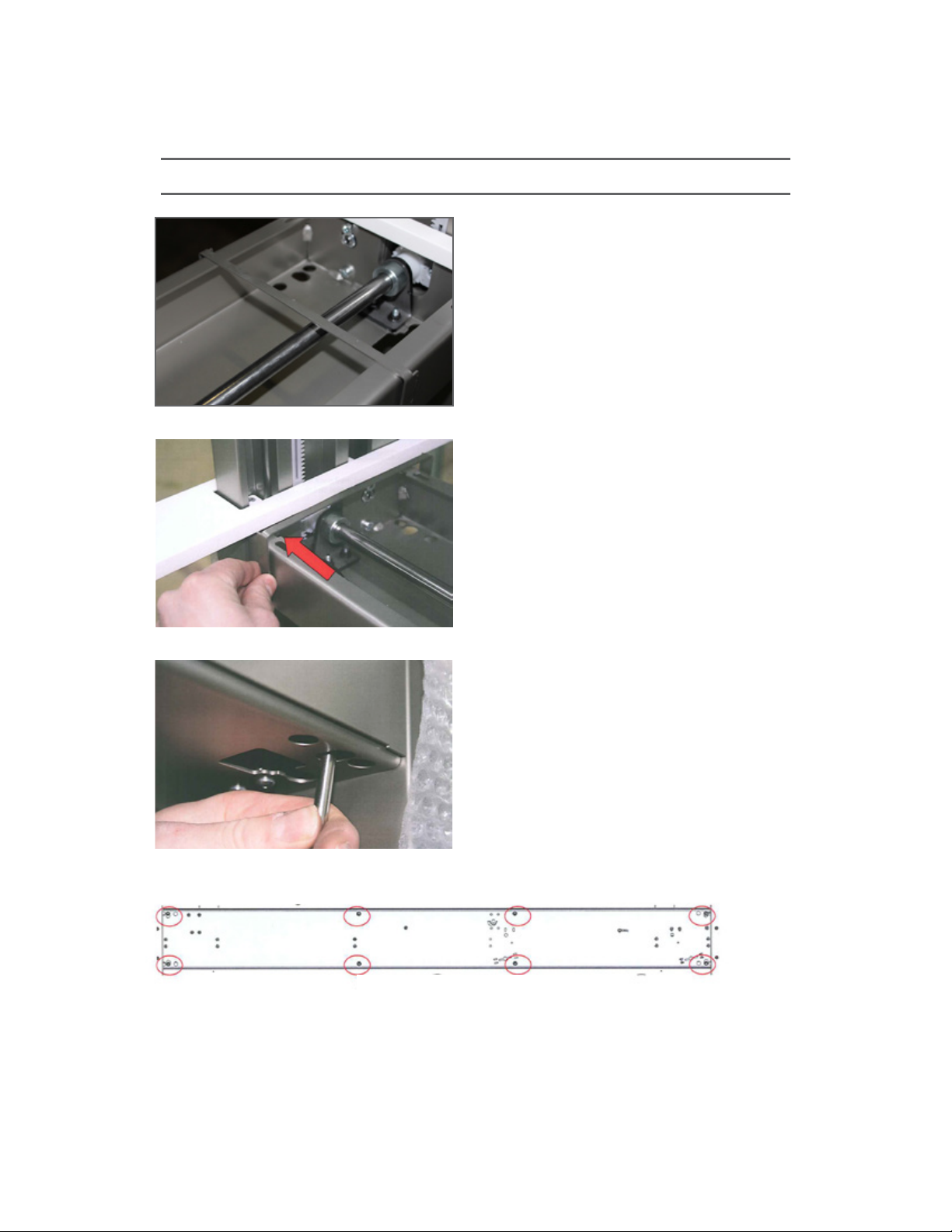
Install spanner tubes between support plates
with the larger diameter access holes
facing down before attaching plates to top
of legs. (pic 12)
Secure support frame to inside of columns
with 4 bolts. (pic 13)
Basic Assembly of Desk Shipped “KD” (knock down)
pic.13
pic.12
a.
b.
WARNING! Examine underside of
worktop. Make sure “drillings”
match top drawings. Top MUST
t ush on work surface
support frame. If accurate
proceed to Step 5.
Generic Drilling Diagram
(your diagram may be different)
eisysDESKING

10
eisys, inc. 112 28th Street South • Birmingham, Alabama 35233 • 205.941.1942 • www.eisys-inc.com
Use wood screws to secure the rest of the
frame to the top. (pic.17)
pic.15
Basic Assembly of Desk Shipped “KD” (knock down)
Attach Work Surface to Support Frame
5.
Be sure the wing nut at the top of each leg is
parallel with the side of the leg so it
will align with the pre-drilled recess in the
work surface (pic.14)
Place Desktop on oor with drillings visible.
Flip Frame upside down and align holes to
drillings. (pic.15)
Align the threaded inserts with holes
in the support plates. Use the 8 bolts
provided to attach the work surface. (pic.16)
a.
b.
pic.14
pic.16
WARNING! The iMove Series uses
a variety of top thicknesses.
VERIFY length of wood screws
are appropriate for the thickness
of the top prior to fastening
d.
c.
pic.17
eisysDESKING
11
eisys, inc. 112 28th Street South • Birmingham, Alabama 35233 • 205.941.1942 • www.eisys-inc.com
Replace Cross Rail Cover and Trim
(as shown).
(pic.18, 19, 20 & 21)
6.
pic.18
pic.19
pic.20
pic.21
cross rail as seen from below
Basic Assembly of Desk Shipped “KD” (knock down)
Slide trim piece into position (pic.18-19)
Align cover on top of cross rail
Screw cover to cross rail using the
8-8mm hex nuts removed in Step 2.
(pic.20)
a.
b.
c.
eisysDESKING

12
eisys, inc. 112 28th Street South • Birmingham, Alabama 35233 • 205.941.1942 • www.eisys-inc.com
Basic Assembly of Desk Shipped “KD” (knock down)
NOTE:
If Desk is integrated into a lowboard/pedestal
jump to Section 2/page 15, install lowboard-
pedestal before moving to Step 8.
Attach Control Panel
7.
Locate the pre-drilled holes on the
underside of the work surface.
Use a #1 Phillips Drive bit.
Once mounted, Control Panel should slide
in & out approximately 1”
(do not over tighten). (pic.23)
Attach cord to the underside of the desk
so that it hangs vertically from the
cross rail (pic.24)
pic.22
pic.23
x cable here
pic.24
a.
b.
c.
M1 Control Panel M2 Control Panel
eisysDESKING

13
eisys, inc. 112 28th Street South • Birmingham, Alabama 35233 • 205.941.1942 • www.eisys-inc.com
Leveling and Calibrating Desk
8.
Level Desk horizontally using the 3
leveling glides on each leg frame.
(pic.25)
If Lowboard/Pedestal on one side,
level Lowboard to leg frame using
glides indicated in pic.25a
Calibrating Desk
Plug desk into standard 120V grounded
power supply.
When the desk is plugged in for the rst time
(or after power is interrupted) the control
panel will ash “000” continuously.
Regardless of the position (height) of the
top, the following reset procedure must be
performed before the desk will be fully
functional.
1. With the desk plugged into a
standard power outlet (M2 only-
control panel IS illuminated and
ashing “000”), press and hold the
down arrow on the control panel.
2. Hold the down arrow until the
desk reaches lowest position and
stops.
3. For M1-Hold the down arrow at
lowest position for 3 seconds.
(M2 only-Continue pressing the
down arrow until the LED stops
ashingandreads“68”).
4. The desk is now ready for use.
Basic Assembly of Desk Shipped “KD” (knock down)
a.
b.
pic.25
pic.25a
If desk makes any unusual
sounds or does not operate
smoothly throughout its FULL
Range of motion, STOP
IMMEDIATELY, refer to Section 5
and call eisys at once.
eisysDESKING

14
eisys, inc. 112 28th Street South • Birmingham, Alabama 35233 • 205.941.1942 • www.eisys-inc.com
Section 2: Attaching the Desk
to the Lowboard/Pedestal
eisysDESKING

15
eisys, inc. 112 28th Street South • Birmingham, Alabama 35233 • 205.941.1942 • www.eisys-inc.com
Step by Step Assembly Instructions
Attaching Desk to Lowboard/Pedestal
9.
pic.26
Attach the support plate using two Spax
Screws (pic.26)
Lift the entire desk to provide a straight entry
for the leg. Then carefully Insert the table leg
into the provided cut-out in the lowboard/
pedestal and seat leg into the recessed
support plate.
(pic.26 & 27)
pic.27
pic.28
From inside the lowboard/pedestal bolt
the cross rail to the top of the lowboard-
pedestal. (pic 28 & 29)
pic.29
a.
b.
c.
eisysDESKING
16
eisys, inc. 112 28th Street South • Birmingham, Alabama 35233 • 205.941.1942 • www.eisys-inc.com
Step by Step Assembly Instructions
9.
pic.30
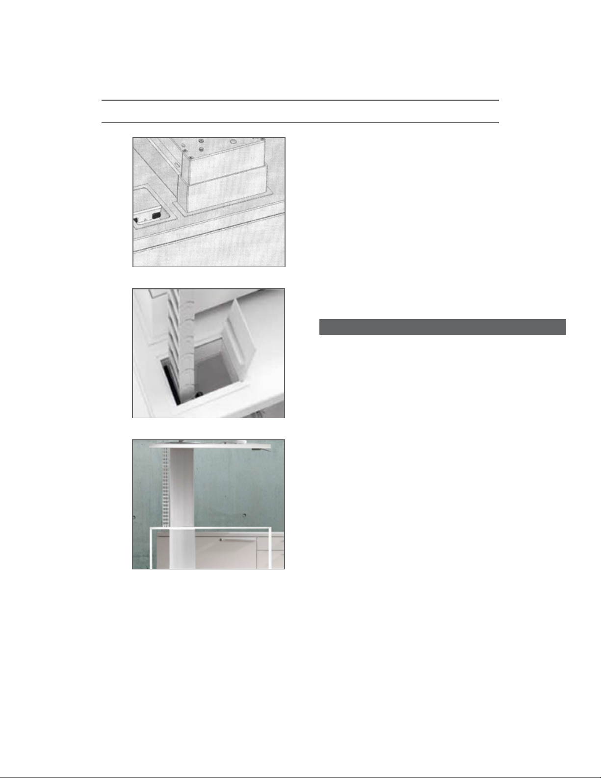
Install U-Shaped metal trim piece around
column (leg). (pic.31)
Install Cable Access/Ventilation Plate
into corresponding cut-out.
(pic.32)
Install Cable Chain to underside of
Desk Top above the lowboard/pedestal.
(pic.33)
pic.31
Attaching Desk to Lowboard/Pedestal
(cont.)
pic.32
d.
e.
NOTE:
f.
Position mounting bracket for Cable Chain
at 90º angle prior to fastening.
Raise Desk to highest position. Allow length
of Cable Chain to enter lowboard/pedestal
2”. Remove any excess Cable Chain from
interior of cabinet.
eisysDESKING

17
eisys, inc. 112 28th Street South • Birmingham, Alabama 35233 • 205.941.1942 • www.eisys-inc.com
Section 3: Accessories
eisysDESKING
18
eisys, inc. 112 28th Street South • Birmingham, Alabama 35233 • 205.941.1942 • www.eisys-inc.com
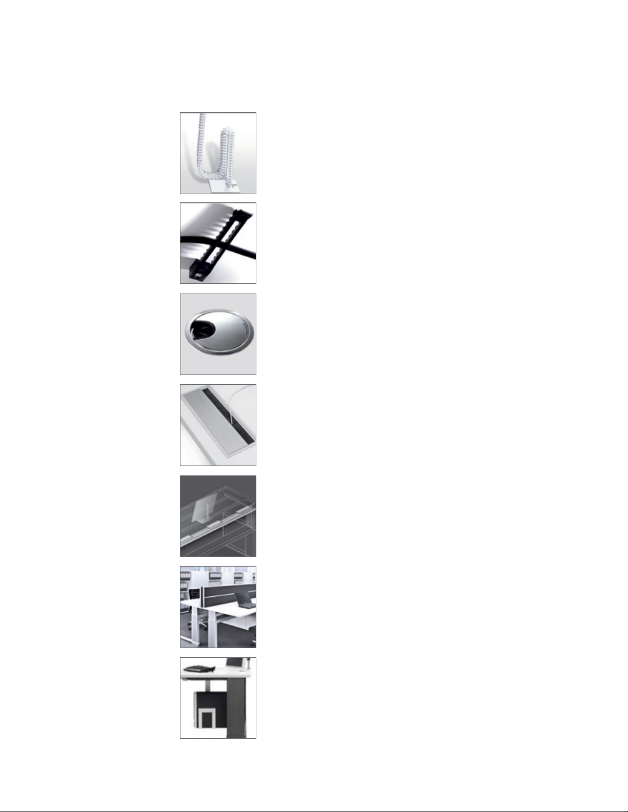
Free Standing Cable Chain
Cable Bows
Desk Top Grommet
Desk Top Data/Power Module
Cable Tray
Desk Top Privacy Panel
See instructions included in the Accessory Box
See instructions included in the Accessory Box
See instructions included in the Accessory Box
See instructions included in the Accessory Box
If not factory installed, install using templates
and instructions provided.
If not factory installed, install using templates
and instructions provided.
CPU Holder
eisysDESKING

19
eisys, inc. 112 28th Street South • Birmingham, Alabama 35233 • 205.941.1942 • www.eisys-inc.com
Section 4: Care and Maintenance
FAQ & Troubleshooting
eisysDESKING

20
eisys, inc. 112 28th Street South • Birmingham, Alabama 35233 • 205.941.1942 • www.eisys-inc.com
Care & Maintenance
Cleaning—
Soft damp cloth only.
No solvent based or abrasive cleaner.
When cleaning a wood veneer surface,
always wipe“with the grain” to avoid creating any
visible scratches.
Lubrication—
Every desk should be fully lubricated at the factory. Should additional
lubrication be required, apply a small aount of lithium grease as
needed. Only apply lubricant to “moving” parts within the cross rail.
Excess lubricant on exposed surfaces of the desk should be cleaned
with warm soapy water and a soft cloth.
1.
2.
*TIP:
eisysDESKING
Table of contents
Other Eisys Indoor Furnishing manuals

Popular Indoor Furnishing manuals by other brands


Rockler
Rockler Blum GRP40163 instructions

MAISONS DU MONDE
MAISONS DU MONDE BAYA 209041 quick start guide

Zintra
Zintra BEAMS CLOSED RAFTER install guide

YitaHome
YitaHome FTLFCT-0026 quick start guide

Furniture of America
Furniture of America CM3010T-7PK Assembly instructions

Keter
Keter COLUMBIA Assembly instructions