EIUK PGS-40 User manual
Rel. 20120523
Operang Manual
PGS‐40 PGS‐60
Calibraon Test Pumps
Content:
Page 2: 1. Safety Instrucons
Page 2: 2. Product Descripon
Page 2: 3. Mounng Instrucons
Page 2: 4. Operaon (pressure)
Page 3: 5. Operaon (vacuum)
Page 4: 6. Maintenance Instrucons
Page 4: 7. Cause of Fault
Page 4: 8. Technical Data
Page 4: 9. Available Accessories / Spares
Tips
This symbol provides you with ps, informaon and notes.
WARNING!
This symbol warns you against acons that can cause damage to persons or to
the instrument.
EiUK ‐ Eutrotron Instruments UK Ltd. • Unit 13 Riley Close • Royal Oak Ind Est • Daventry • Northants NN11 8QT • England U.K.
Phone: +44 (0) 1327 871044 • E‐Mail: sales@eurotron‐uk.com • Internet h p://www.eurotron‐uk.com
Operang Manual
•PGS‐40 PGS‐60
1
Operang Manual
PGS‐40 • PGS 60
EiUK ‐ Eutrotron Instruments UK Ltd. • Unit 13 Riley Close • Royal Oak Ind Est • Daventry • Northants NN11 8QT • England U.K.
Phone: +44 (0) 1327 871044 • E‐Mail: sales@eurotron‐uk.com • Internet h p://www.eurotron‐uk.com
1. Safety Instrucons
Read this manual carefully prior to
operang the calibraon test pump
PGS‐40 or PGS‐60. The pressure inside
the pump can be extremly high. Ensure
that all pressure connecons have been
established correctly.
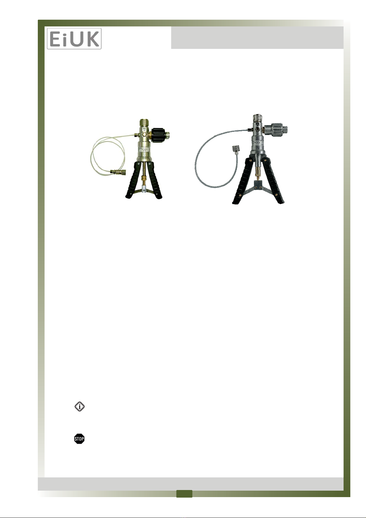
2. Product Descripon
The calibraon test pump is used to generate
pressure and vacuum for checking, adjusng and
calibrang mechanical and electronic pressure
measuring instruments by comparave
measurements. These pressure tests may be
carried out in laboratories, workshop or on site at
the measuring point.
If the instrument to be tested and a sufficiently
accurate reference measuring instrument are
connected up to the test pump, the same pressure
is applied to the two measuring instruments when
the pump is operated.
By comparing the two measure values at random
pressure values, the accuracy can be verified or the
instrument under test can be adjusted.
Despite its compact dimensions, the calibraon
test pump is easy to operate and allows for exact
generaon of the required test pressures; a
change‐over switch enables the generaon of
vacuum as well. The pump is fi ed with a fine
adjustment valve for generaon of high pressure
and precise adjustment of pressures. The
reference instrument is screwed directly on the top
of the pump and the unit under test is connected
by means of the connecon tube incorportang an
adapter 1/4" BSP female thread, contained in the
scope of delivery.
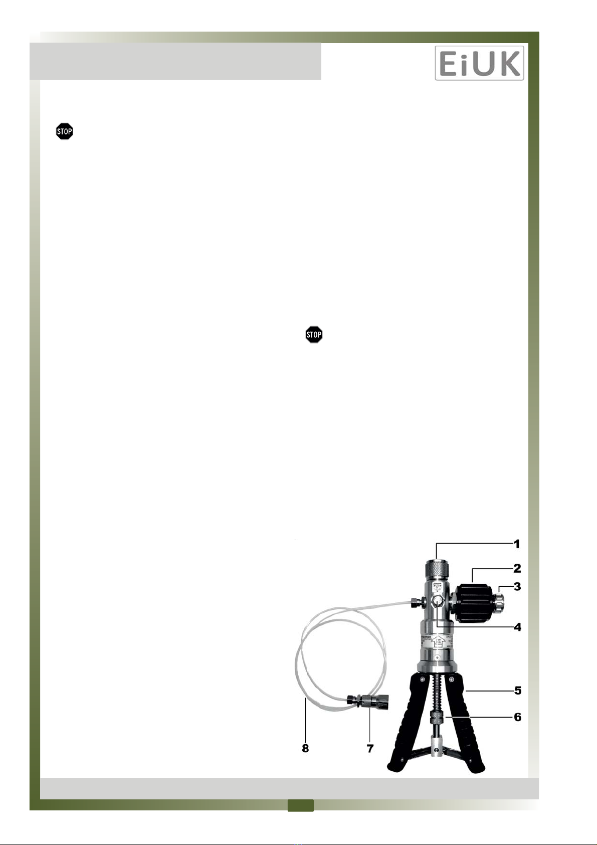
(1) = pressure connector for reference instrument
(2) = high pressure generaon and
fine adjustment valve
(3) = pressure relief valve
(4) = change‐over switch for pressure / vacuum
(5) = handles
(6) = adjustable knurled nut for the adjustment
of the delivery rate of the pump
(7) = pressure port for test specimen
(8) = test tube, length approx. 0.5 m
3. Mounng Instrucons
The reference instrument is fi ed to the upper side
of the calibraon pump. Fingerght fastening of
the reference instrument with the knurled nut is
sufficient. The reference instrument is sealed by
the integral O‐ring sealing gasket.
The unit under test is mounted to the end of the
flexible tube. Fingerght fastening of the unit
under test is sufficient. The unit under test is
sealed by the integral O‐ring sealing gasket.
In order to adapt different connecon threads of
units under test, use adaptors of the several
adapter sets with integral O‐ring sealing gaskets,
available as accessory for the calibraon pump.
Do not use Teflon tapes,
this may damage your test pump.
You can unsrew the tube and also directly a ach
the unit under test to the pump body, using a
suitable thread adapter. This decreases the volume
of the calibraon circuit and makes operaon of
the test pump more easy.
4. Operaon (pressure)
First, check wether the change‐over valve (4) has
to be actuated (see scker on the device). For this
purpose use a pen or a small screw‐driver. The
encasement of the switch is intended to help
prevent unintenonal actuaon.
2
EiUK ‐ Eutrotron Instruments UK Ltd. • Unit 13 Riley Close • Royal Oak Ind Est • Daventry • Northants NN11 8QT • England U.K.
Phone: +44 (0) 1327 871044 • E‐Mail: sales@eurotron‐uk.com • Internet h p://www.eurotron‐uk.com
Operang Manual
•PGS‐40 PGS‐60
Never actuate the change‐over valve (4)
when the test pump is under pressure or
vacuum! Actuate the change‐over valve
only, when the relief valve (3) is open.
Make sure that the pressure relief valve (3) is not
closed completely.
Turn the fine adjustment valve (2) anclockwise up
to the end (smooth „stop“ can be felt).
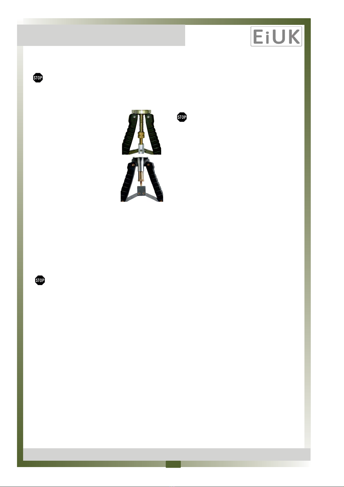
Make sure, that the adjustable knurled nut (6) is in
such a posion, that the visible spring (or bushing)
above the nut has some clearance, if the handles
(5) are pressed together.
Carefully turn the pressure relief valve (3) unl the
valve closes. You will not nofy any „hard stop“.
Operate the hand pump (5) unl the max. priming
pressure is achieved:
PGS‐40: approx. 20 ‐ 25 bar
PGS‐60: approx. 35 ‐ 40 bar
Turn the fine adjustment valve (2) clockwise to
increase the pressure to maximum
PGS‐40: approx. 40 bar
PGS‐60: approx. 60 bar.
The max. pressure value depends on the volume of
the calibraon circuit.
Move the fine adjustment valve (2) unl the
requested test pressure has been reached
precisely (to be read on the reference instrument).
Aer increasing the pressure, the reading
may slightly drop again for about 30 sec.
This is caused by thermodynamic effects,
the tube connecon and the sealing
gaskets. If the pressure drop does not
come to a standsll, check the measuring
circuit for ghtness.
Due to the low volume of each
compression stroke of the test pump,
only small volume test specimen should
be tested.
A pressure reducon is achieved by turning the
fine adjustment valve (2) counter‐clockwise first
and then by carefully opening the relief valve (3).
Remove the reference instrument or the
test specimen only when the relief
valve (3) is open and no pressure is in the
test pump any more.
5. Operan (vacuum)
First, check wether the change‐over valve (4) has
to be actuated (see scker on the device). For this
purpose use a pen or a small screw‐driver. The
encasement of the switch is intended to help
prevent unintenonal actuaon.
Never actuate the change‐over valve (4)
when the test pump is under pressure
or vacuum! Actuate the change‐over
valve only when the relief valve (3) is
open.
Make sure that the pressure relief valve (3) is not
closed completely.
Make sure, that the adjustable knurled nut (6) is in
such a posion, that the visible spring (or bushing)
above the nut has some clearance, if the handles
(5) are pressed together.
Turn the fine adjustment valve (2) clockwise up to
the end (“stop“ can be felt).
Carefully turn the pressure relieve valve (3) unl
the valve closes. You will not nocy any „hard
stop“.
Operate the handles (5) smoothly and slowly unl
approx. ‐0.9 bar of vacuum are reached.
Turn the fine adjustment valve (2) an‐clockwise to
increase vacuum up to ‐0.95 bar. Turn this valve for
fine‐adjustment.
Aer increasing the vacuum, the reading
may slightly drop again for about 30 sec.
This is caused by thermodynamic effects,
the tube connecon and the sealing
gaskets. If the vaccum drop does not
come to a standsll, check the measuring
circuit for ghtness. Due to the low
volume of each compression stroke of the
test pump, only small volume test
specimen should be tested.
3
Operang Manual
PGS‐40 • PGS 60
EiUK ‐ Eutrotron Instruments UK Ltd. • Unit 13 Riley Close • Royal Oak Ind Est • Daventry • Northants NN11 8QT • England U.K.
Phone: +44 (0) 1327 871044 • E‐Mail: sales@eurotron‐uk.com • Internet h p://www.eurotron‐uk.com
A vacuum reducon is achieved by carefully
opening the relief valve (3).
Remove the reference instrument or the
test specimen only when the relief
valve (3) is open and no vacuum is in the
test pump any more.
For a maximal performance of the
test pump, please make sure that
the adjustable knurled nut is
adjusted to a posion that the
visible spring (or bushing) get some
clearance. If you operate with a
reference or test item with small
pressure range, you can reduce the
performance of the pump by
turning the nut (6) upwards. This
reduces the volume per stroke.
6. Maintenance Instrucons
Prior to connecng the reference instrument and
the test specimen, the sealing gaskets in the two
connectors should be checked for correct posion
and wear, and should be replaced, if and when
necessary. A service kit, consisng of spare sealing
gaskets and o‐rings, is available as an accessory.
The test pump must not be soiled, and in
parcular it must not get into contact
with fluid or agressive media.
7. Case of Fault
If the pressure or vacuum cannot be generated
correctly or if the set pressure or vacuum does not
stay stable, this is likely to be caused by the
incorrectly posioned or selected sealing gaskets.
Please also check wether any adapters used on the
test specimen have been ghtened sufficiently to
eliminate leaks.
Before assuming there is a leak in the test pump:
First of all, check if the relief valve (3) is closed and
if the pressure/vacuum change‐over switch (4) is
correctly posioned and has not come to test in a
„centre posion“.
If the test pump has not been used for a longer
period of me, the first li may be somewhat
sluggish. This effect will disappear again during
further operaon.
By no means apply any force to the operang
elements of the test pump.
Never connect an external pressure
supply system to the PGS‐40 / PGS‐60
test pump.
8. Technical Data
Pressure range:
PGS‐40 PGS‐60
‐0.95...+40 bar ‐0.95...+60 bar
Medium: air
Pressure ports (standard version):
1/2" BSP female rotang for reference instrument
1/4" BSP female rotang for test specimen
High pressure generaon and Fine adjustment:
Fine adjustment valve
Overpressure:
Adjustable by means of knurled nut.
Material: Aluminium, brass, ABS, NBR
Dimensions:
PGS‐40 PGS‐60
220 x 120 x 65 mm 290 x 185 x 65 mm
Standard supply:
connecon tube, length approx. 0.5 m
9. Available Accessories / Spare Parts
• Sets of adapters for test specimen
‐ BSP threads (1/8", 3/8", 1/2", 1/2" male)
‐ NPT threads (1/8", 1/4", 3/8", 1/2")
‐ Metric (M12x1.5, M20x1.5, Minimess 1620)
• Transit case with custom foams
• Service kit
• Spare part: hose assembly
• Spare part: volume control with relief valve
4
This manual suits for next models
1
Other EIUK Water Pump manuals

Popular Water Pump manuals by other brands

EINHELL
EINHELL GE-DP 7330 LL ECO Original operating instructions

Varian
Varian HS452 instruction manual

Neptun
Neptun NCBP-E 18 Original operating instructions

GORMAN-RUPP
GORMAN-RUPP T6A60S-4045T-ESP Installation, operation and maintenance

Dover
Dover Wilden Advanced Metal P200 Series operation & maintenance

EBARA
EBARA EV-A10 instruction manual


