Ekars ERM-2120 User manual

ERM-2120/
2240/2320
Public Address
Remote Amplifier
OPERATING MANUAL
10
10
0
MIC
MIC
EXT
EXT
LEVEL
LEVEL
ALL 4
ALL 4
ALL 1
ALL 1
ALL 2
ALL 2
ALL 3
ALL 3
ZONE SELECTOR
ZONE SELECTOR
SOURCE
SOURCE
MONITOR
MONITOR
25
25
26
26
27
27
28
28
29
29
30
30
31
31
32
32
18
18
19
19
20
20
21
21
22
22
23
23
24
24
17
17
78
8
653 421
910
10
11
11
12
12
13
13
14
14
15
15
16
16
CHIME
CHIME
-20
-20
+60dB
+60dB
GAIN
GAIN
CHIME
CHIME
-12dB
-12dB
+12dB
+12dB
+10dB
+10dB
10
10
0
-10
-10
0
+6
+6
dB
dB
0
LM
LM
HM
HM
EQ
EQ
LEVEL
LEVEL
-12dB
-12dB
+12dB
+12dB
0
20
20
30
30
40
40
50
50
2
4 6
8
PUBLIC ADDRESS REMOTE AMPLIFIER ERM-2320
MIC
MIC
LEVEL
LEVEL
POWER
POWER
12
3
B
PUSH

Contents
1
1.Unpacking And Installation ---------------------------------------------------------- 2
2.Features ---------------------------------------------------------------------------------- 3
3.Front Panel I ---------------------------------------------------------------------------- 4
4.Front Panel II ---------------------------------------------------------------------- 5.6
5.Rear Panel ------------------------------------------------------------------------------ 7
6.Mode selector switch combinations ----------------------------------------------- 8
7.Specifications ----------------------------------------------------------------------------- 9
SamHyoung Electronics Co., Ltd.
3Ra-618, Shihwa Industrial Complex, #1378, Jungwang-Dong,
Shiheung-City, Kyonggi-Do, Korea (429-450)
Tel : 82)31+432+5112 / 82)31+432+4422
Fax: 82)31+432+5450 / 82)31+431+1690
Home Page : http://www.ekars.co.kr
http://www.samhyoung.co.kr

2
Although it is neither complicated to install nor difficult to operate your Remote Amplifier,
a few minutes of your time is required to read manual for a properly wired installation
and becoming familiar with its many features and how to use them.
Please take a great care in unpacking your Remote Amplifier and do not discard the
carton and other packing materials.
They may be needed with when moving your set and are required if it ever becomes
necessary to return your set for service.
Never place the unit radiators, in front of heating vents, in excessively humid or dusty
location to avoid early damage and for your years of quality use.
Connect your complementary components as illustrated in the following page.
The instruction for use shall state that the apparatus shall not be exposed to dripping or
splashing and that no objects filled with liquids, such as vases, shall be placed on the
apparatus.
Unpacking And Installation
CAUTION
CAUTION
RISK OF ELECTRIC SHOCK
DO NOT OPEN
RISK OF ELECTRIC SHOCK
DO NOT OPEN
CAUTION
:
TO REDUCE THE RISK OF ELECTRIC SHOCK.
DO NOT REMOVE COVER (OR BACK).
NO USER-SERVICEABLE PARTS INSIDE.
REFER SERVICING TO QUALIFIED
SERVICICE PERSONNEL.
TO PREVENT FIRE OR SHOCK HAZARD,
WARNING
:
DO NOT EXPOSE THE UNIT TO RAIN OR
MOISTURE.
This symbol is intended to alert the user to the
presence of important operation and maintenance
(servicing) instructions in the literature
accompanying the appliance.
This symbol is intended to alert the user to the
presence of uninsulted "dangerous voltage"
with in the product's enclosure that may be of
sufficient magnitude to constitute a risk of
electric shock to persons.
To prevent electric shock do not use this
(polarized) plug with an extension cord,
receptacle or other outlet unless the blades can
be fully inserted to prevent blade exposure.
:
CAUTION

Features
3
Attached Combination Jack for gooseneck microphone
or any wired microphones.
Low noise high gain mic pre amplifier with gain POT and mute switch.
Including natural 4-note chime sound with gain POT.
Two mid band equalizer support for controlled human voice spectrum.
Built in amplifier and speaker served internal or external sound source.
Automatically muted avoid feedback problem between attached mic
and internal monitor speaker.
1ch of extra input for monitor signal input.
Independent each zone control switches and status indicator.
Built in electric balanced circuit for avoid ground loop problems.
High accurate 4-step LED VU to trace program signal output.
Supporting various electrical interfacing method.
Heavy duty outer case.

Front Panel I
4
1. Main Power Switch - Power "ON" and "OFF" procedure.
Please turn on this rocker switch before operating the ERM-2120, 2240, 2320 series
remote amplifier. The "POWER" green color LED is indicating when enclosed external
24VDC/1A DC adapter working properly.
All electrical function will be ready within 2 second causing start initialize circuit.
Should be reset(turned off) all of "ZONE SELECTOR" switch before acting power switch
on or off to avoid any audible pop noise via connected extra PA equipment.
2. 4-dot Bargraph LED VU Meter - Displaying audio signal output level.
Each LED is tracing signal output level that comes from MIC and CHIME signal.
Please make adequate mic and chime level controlled by each potentiometers.
We recommend that bargraph LED should display range over than -10dB
for below than +6dB LED indication.
3. CHIME Level - CHIME signal output level control.
Please fixed level refer to bargraph LED VU(below than 0dB, when the chime signal
make peak value)or destination speakers chime SPL. 4-Notes chime sound is useful
for pre announcement. It is not necessary to make big sound volume.
4. LM and HM EQUALIZER - Low MId(500Hz) and High MId(5KHz)band equalizer.
The mid band equalizer can easily make clear sound against absorbing or reflecting
energy from sound field. Center flat point and +/-12dB adjustable peaking resonance
type equalizer.
5. MIC Gain Control - Mic headamp boost gain control
This potentiometer can cover level of entire dynamic microphone sensitivity.
The maximized boost gain is up to +60dB(CW), minimum +10dB(CCW) that continually
controlled end to end point. Please make the boost gain of attached gooseneck
microphone refer to bargraph LED indicating status. Normally, can find ideal point of
boost gain between +30dB and +50dB scale of mic gain potentiometer.
6. MIC input connector - XLR jack or 1/4" Phone jack acceptable.
Please find enclosed gooseneck microphone and properly couple with this connector.
Enclosed microphone that has uni directional acoustic axis characteristics should
made on axis and maintained adequate distance 50 to 100m/m between mic head
assembly and mouth.
-20
-20
+60dB
+60dB
GAIN
GAIN
CHIME
CHIME
-12dB
-12dB
+12dB
+12dB
+10dB
+10dB
10
10
0
-10
-10
0
+6
+6
dB
dB
0
LM
LM
HM
HM
EQ
EQ
LEVEL
LEVEL
-12dB
-12dB
+12dB
+12dB
0
20
20
30
30
40
40
50
50
2
46
8
PUBLIC ADDRESS REMOTE AMPLIFIER ERM-2320
MIC
MIC
LEVEL
LEVEL
POWER
POWER
12
3
B
PUSH
12
3
4
5
6

Front Panel II
5
1010
00
MIC
MIC
EXT
EXT
LEVEL
LEVEL
ALL 4
ALL 4
ALL 1
ALL 1
ALL 2
ALL 2
ALL 3
ALL 3
ZONE SELECTOR
ZONE SELECTOR
SOURCE
SOURCE
MONITORMONITOR
25
25
26
26
27
27
28
28
29
29
30
30
31
31
32
32
18
18
19
19
20
20
21
21
22
22
23
23
24
24
17
17
78
8
653 421
910
10
11
11
12
12
13
13
14
14
15
15
16
16
CHIMECHIME
12
3
44
55
66
V
V
1. ZONE SELECTOR/ALL switch - Control switch with LED indicator.
(ERM-2120=x1, ERM-2240=x2, ERM-2320=x4 each of ALL switches)
Each of "ALL" switch handle to "ON" status relating to definite row direction switch array.
It is not related to each of switch's on or off status when forced on status by specific
ALL switch but return to preset status when release the specific ALL switch.
2. ZONE SELECTOR/CHANNEL SWITCH - Control switch with LED indicator.
(ERM-2120=x12, ERM-2240=x24, ERM-2320=x32 each of channel selector switches)
Each channel switching circuit supports individual switching point between channel out
and combined "REMOTE COM" terminal and one to one correspondence of specific
channel out terminal block on rear panel.
: Please do not apply and switch any high voltage or high current.
All of the switching circuit nominal capacity is up to 48VDC/0.1A into resistive load.
: Please released(push-OFF) all of "ZONE SELECTOR" section switches, after use them.
If not, sometimes interrupted the PA system main program signal when those switches
are maintain "ON" position.
3. SOURCE/MIC switch - Control switch with LED indicator.
This switch controls to attached gooseneck mic on or off.
The internal monitor speaker volume will be -20dB reduced to preventing self acoustical
feedback problem when activate this switch.

Front Panel II
6
10
10
0
MICMIC
EXT
EXT
LEVEL
LEVEL
ALL 4ALL 4
ALL 1
ALL 1
ALL 2ALL 2
ALL 3ALL 3
ZONE SELECTORZONE SELECTOR
SOURCE
SOURCE
MONITOR
MONITOR
25
26
27
28
29
30
31
32
18
19
20
21
22
23
24
17
7
8
6
5
3
4
2
1
9
10
11
12
13
14
15
16
CHIME
CHIME
1122
33
4
5
6
4. SOURCE/CHIME switch - Momentary push switch, trigger chime signal.
This switch controls internal integrated 4-notes chime signal generator.
Appear in complete 4-notes chime signal when it pressed one time.
5. MONITOR/MONITOR volume - Control to internal speaker monitoring volume.
The ERM-2120/2240/2320 remote amplifier integrated 2inch(50m/m)/1W speaker
with small power amplifier for monitoring internal chime signal or external signal source.
( : Monitor sound volume is almost muted when status of MIC switch on.)
6. MONITOR/EXT switch - control switch with LED indicator
For exchanging monitor signal.
Please apply external signal(Typical=0dB)to MONITOR INPUT terminal on rear panel if
necessary to monitor via internal speaker. The external monitor input is not related main
SIGNAL OUTPUT and LED VU meter, but support hearing monitor only.
( : Please connect external series resistor into monitor input + and -, if it is necessary
to monitoring high level signal.
For example : Monitoring 100V speaker line ---> Please connect 1.2Mohm series resistor
between MONITOR INPUT terminal block and 100V line)
Rear Panel
7
RMT
COM
RMT
COM
www.ekars.co.kr
www.ekars.co.kr
PUBLIC ADDRESS
PUBLIC ADDRESS
REMOTE CONTROL AMP
REMOTE CONTROL AMP
MODEL NO : ERM-2320
MODEL NO : ERM-2320
MADE IN KOREA
MADE IN KOREA
TO REDUCE THE RISK OF FIRE
OR ELECTRIC SHOCK DON'T EXPOSE THIS
EQUIPMENT TO RAIN OR MOISTURE.
WARNING
:
MONITOR
INPUT
MONITOR
INPUT
SIGNAL
OUTPUT
SIGNAL
OUTPUT
G G
DC INPUT
DC INPUT
24V
24V
24
24
23
23
22
22
21
21
20
20
19
19
18
18
17
17
16
16
15
15
14
14
13
13
12
12
11
11
10
10
98732
32
31
31
30
30
29
29
28
28
27
27
26
26
25
25
654 3 2 1
1~6
1~6
SN
1
2
4
3
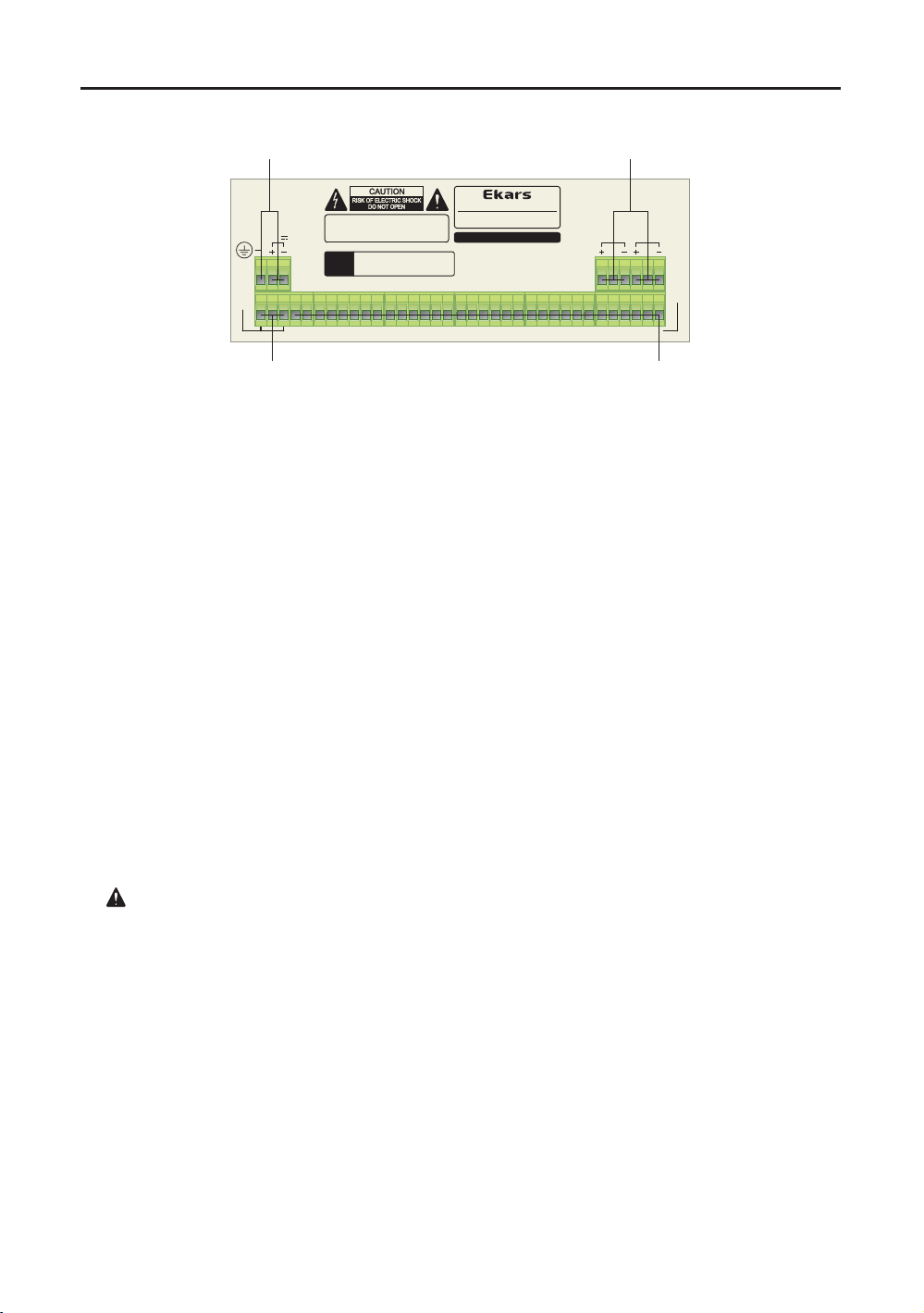
1. SIGNAL OUTPUT and MONITOR INPUT/ 6p-Terminal block
Please pull out to backward of 6p-female terminal block before wiring.
Should refer to rear panel's printed subject of electric function and polarity.
The main signal flows out via the SIGNAL OUTPUT terminals that built by electronically
balanced circuits.
Should be open "-" terminal if connected with any unbalanced input.
MONITOR INPUT terminal for extra monitor input. (Electronic 10Kohm balanced input)
Typical monitor input level is -10dBm(245mV) for 1W monitoring sound power.
Please make wire bridge between terminal "G" and terminal "-" if connected
with unbalanced signal source.
2. ZONE SELECTOR OUTPUT Terminal block
Rated each mechanical contact switching circuit capacity is up to 48VDC/0.1A
(ERM-2320=125VAC/0.5A, 24VDC/1A max) that recommend control
to external relay circuits. Normally open, closing between selected specific zone switch
out and REMOTE COMMON out.
: Please used under the guarantee of rated switching capacity.
3. REMOTE COMMON Terminal block
This terminal is the reference of contact point of whole switching circuits.
4. 24V DC INPUT and FRAME GROUND Terminal block
Please find enclosed extra 24VDC power supply and plug in.
All of ERM series is prevented against over current cause the abnormal current flow
comming from switching circuits or internal circuit failure. It is automatically released
when resolving trouble.
Please make proper connection with earth for safety via the frame ground terminal.
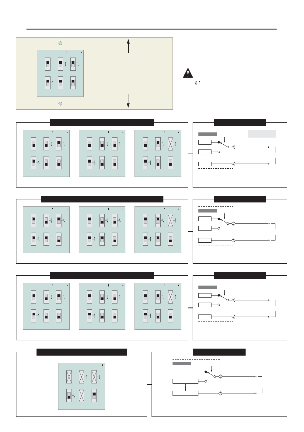
Mode selector switch combinations
8
DESCRIPTION
* Reversed current flow directions against
DC VOLTAGE OUTPUT/HIGH-ACTIVE.
nc
no
CHANNEL OUTPUT
0V
+DCV
ON
REMOTE
COMMON OUTPUT
1~n
To local
ERM Series
+DCV
DESCRIPTION
* The DC voltage output goes to high(5V, 12V, 24V)
when activated(ON) specific channel switch.
nc : Normal close
no : Normal open
nc
no
CHANNEL OUTPUT
0V
+DCV
ON
0V
REMOTE
COMMON OUTPUT
1~n
To local
ERM Series
DESCRIPTION
* The DC voltage output goes to low(0V)
when activated(ON) specific channel switch.
nc
no
CHANNEL OUTPUT
0V
ON
REMOTE
COMMON OUTPUT
1~n
To local
ERM Series
+DCV
0V
<BOTTOM SIDE VIEW>
REAR SIDE
FRONT SIDE
SW 3
ALL PHASE
SW 2
V-SOURCE
SW 1
V-OUT
SW 6
ALL FLOAT
SW 5
COM PHASE
SW 4
SW PHASE
VIN
REG
5V
12V
C
O
MODE SELECTOR ON / OFF
DESCRIPTION
* Provide to electrical contact loop when activated(ON)
specific channel switch.
nc
no
CHANNEL OUTPUT
ON
REMOTE
COMMON OUTPUT
1~n
To local
ERM Series
CONTACT A
CONTACT B
LINKED
The power switch should turn off before
making new switch combinations.
The power switch should turn off before
making new switch combinations.
Please do not care.
Please do not care.
ELECTRICAL CONTACT OUTPUT
SW 3
ALL PHASE
SW 2
V-SOURCE
SW 1
V-OUT
SW 6
ALL FLOAT
SW 5
COM PHASE
SW 4
SW PHASE
VIN
REG
5V
12V
C
O
MODE SELECTOR ON / OFF
DC VOLTAGE OUTPUT / LOW-ACTIVE
5V 12V 24V
SW 3
ALL PHASE
SW 2
V-SOURCE
SW 1
V-OUT
SW 6
ALL FLOAT
SW 5
COM PHASE
SW 4
SW PHASE
VIN
REG
5V
12V
C
O
MODE SELECTOR ON / OFF
SW 3
ALL PHASE
SW 2
V-SOURCE
SW 1
V-OUT
SW 6
ALL FLOAT
SW 5
COM PHASE
SW 4
SW PHASE
VIN
REG
5V
12V
C
O
MODE SELECTOR ON / OFF
SW 3
ALL PHASE
SW 2
V-SOURCE
SW 1
V-OUT
SW 6
ALL FLOAT
SW 5
COM PHASE
SW 4
SW PHASE
VIN
REG
5V
12V
C
O
MODE SELECTOR ON / OFF
REVERSED VOLTAGE OUTPUT / HIGH-ACTIVE
5V 12V 24V
SW 3
ALL PHASE
SW 2
V-SOURCE
SW 1
V-OUT
SW 6
ALL FLOAT
SW 5
COM PHASE
SW 4
SW PHASE
VIN
REG
5V
12V
C
O
MODE SELECTOR ON / OFF
SW 3
ALL PHASE
SW 2
V-SOURCE
SW 1
V-OUT
SW 6
ALL FLOAT
SW 5
COM PHASE
SW 4
SW PHASE
VIN
REG
5V
12V
C
O
MODE SELECTOR ON / OFF
SW 3
ALL PHASE
SW 2
V-SOURCE
SW 1
V-OUT
SW 6
ALL FLOAT
SW 5
COM PHASE
SW 4
SW PHASE
VIN
REG
5V
12V
C
O
MODE SELECTOR ON / OFF
DC VOLTAGE OUTPUT / HIGH-ACTIVE
5V 12V 24V
SW 3
ALL PHASE
SW 2
V-SOURCE
SW 1
V-OUT
SW 6
ALL FLOAT
SW 5
COM PHASE
SW 4
SW PHASE
VIN
REG
5V
12V
C
O
MODE SELECTOR ON / OFF
SW 3
ALL PHASE
SW 2
V-SOURCE
SW 1
V-OUT
SW 6
ALL FLOAT
SW 5
COM PHASE
SW 4
SW PHASE
VIN
REG
5V
12V
C
O
MODE SELECTOR ON / OFF
SW 3
ALL PHASE
SW 2
V-SOURCE
SW 1
V-OUT
SW 6
ALL FLOAT
SW 5
COM PHASE
SW 4
SW PHASE
VIN
REG
5V
12V
C
O
MODE SELECTOR ON / OFF

Specifications
9
Mic headamp
Maximum Gain ----------------------------------------------------------------------------------- +60dB
Signal to noise ratio ----------------------------------------------- More than -60dB(Gv=+60dB,
150ohm terminated, BW=20Hz to 20KHz)
Frequency response ----------------------------------------- 80Hz to 18KHz(-3dB/Gv=+40dB)
THD ------------------------------------------------------------ Less than 0.1%(Gv=+60dB, 1KHz)
Equalizer
Low middle ---------------------------------------------------------- F0=500Hz Peaking, +/- 12dB
High middle ----------------------------------------------------------- F0=5KHz Peaking, +/- 12dB
Chime
4-note chime -------------------------------------------------------------------------- Do, Mi, Sol, Do
Switching circuit
Maximum switching capacity --------------------------------------------------- DC48V 0.2A max
Normal switching capacity ------------------------------------------------------------- DC24V 0.1A
Power requirement
DC24V/0.5A max ------------------ Exclude external switching circuit power consumption
Specifications and design are subjected to change without notice for improvements.

Memo
10
3rd floor, 271-183, Kochk-2Dong,
Guro-Gu, Seoul, Korea (152-082)
Tel : 82)2+2612+4422
Fax : 82)2+2612+7676
Seoul office.
936-4, Kumuncheoun-Ri, Hyangnam-Myun,
Hwaseong-City, Kyunggi-Do, Korea (445-922)
Tel : 82)31+432+5112 / 82)31+432+4422
Fax : 82)31+352+7637 / 82)31+352+7649
Home Page : http://www.ekars.co.kr / http://www.samhyoung.co.kr
Headquarter & Overseas Dep.
MEMO
PUBLIC ADDRESS TOTAL SOLUTION
This manual suits for next models
2
Table of contents
Other Ekars Amplifier manuals


Popular Amplifier manuals by other brands

Behringer
Behringer Thunderbird BX108 user manual

Cary Audio Design
Cary Audio Design HH-1 owner's manual

Ecler
Ecler eWAMPBT+ user manual

Conrad-johnson design
Conrad-johnson design Sonographe SC-1 owner's manual

Goldmund
Goldmund TELOS 153 user manual

AUSTRALIAN MONITOR
AUSTRALIAN MONITOR DCM120 Specifications


