Ekoterm GP sc Series User manual

Pellet burner GP xx sc 1
MANUAL
FOR INSTALLATION, OPERATION AND MAINTENANCE OF
AN AUTOMATED PELLET BURNER FROM SERIES
„GP XX SC”
www.greenecotherm.eu

Pellet burner GP xx sc 2
The manufacture company thanks you for your choice.
The manufacture company submits this manual to help the team that will install, adjust and
service the pellet burner, as well as to the customer that will operate it.
The manufacturing company requires that the technicians, performing the above mentioned
procedures, had successfully passed the product’s technical training.
Manufacturer Ekoterm Proekt EAD
Address Bulgaria, 6300 Haskovo, 67 Saedinenire blvd.
Phone +359 800 15 145
Fax +359 38 60 30 45
E-mail [email protected]
Web site www.ecotherm.bg
Edition: 11 July 2017

Pellet burner GP xx sc 3
CONTENT
page.
1. USERS SAFETY INFORMATION. ................................................................................................................. 4
2. DESCRIPTION AND ADVANTAGES OF THE AUTOMATED PELLET BURNER „GP XX SC”. ................... 5
3. TECHNICAL DATA OF THE PELLET BURNER FROM SERIES „GP XX SC”. ............................................. 7
4. CONSTRUCTION DESCRIPTION OF THE PELLET BURNER “GP XX SC”. ............................................... 9
4.1. GENERAL CONDITIONS. ................................................................................................................... 9
5. MOUNTING AND INSTALLATION OF THE PELLET BURNER. ................................................................. 11
5.1. MAIN REQUIREMENTS FOR INSTALLATION OF A PELLET BURNER „GP XX SC”. .....................11
5.2. INSTALLATION OF THE PELLET BURNER. ....................................................................................11
5.3. OVERALL DIMENSIONS OF THE BURNER’S MAIN MODULE. .......................................................12
5.4. POSITIONING AND MOUNTING OF THE BURNER’S MODULES. ..................................................13
5.5. INFORMATION ABOUT INSTALLATION AVAILABILITIES OF PELLET BURNER „GP XX SC” AND
ITS CO-OPERATION WITH HOT WATER BOILERS. .....................................................................................14
6. INITIATION TO OPERATION OF THE PELLET BURNER „GP XX SC”...................................................... 15
6.1. MAIN REQUIREMENTS ABOUT THE USED FUEL TYPES. ............................................................15
6.2. INITIATION TO OPERATION OF A PELLET BURNER „GP XX SC”. ................................................15
6.2.1. INTERFACE PANEL OF AN AUTOMATED PELLET BURNER “GP XX SC”. .......................... 16
6.2.2. CONNECTING AND POWER SUPPLYING OF THE BURNER. .............................................. 16
6.2.3. SWITCHING ON THE PELLET BURNER FROM SERIES „GP XX SC”. .................................. 17
6.2.4. ALGORITHM OF OPERATION OF A PELLET BURNER „GP XX SC”. .................................... 18
6.2.5. OPERATIONAL PARAMETERS FOR ADJUSTMENT OF A PELLET BURNER „GP XX SC”. 19
6.2.6. DESCRIPTION OF THE PRIMARY MENU, THE METHODS OF STARTING AND
OPERATIONAL PARAMETERS ADJUSTMENT OF A PELLET BURNER „GP XX SC”. .................................. 20
6.2.7. BURNER ADJUSTMENTS ACCORDING TO THE CONSUMED HEATING OUTPUT. ........... 23
6.2.8. NOMINAL OPERATION MODE OF THE BURNER. ................................................................. 23
6.2.9. OPERATION MODES OF A PELLET BURNER FROM SERIES „GP XX SC”. ........................ 23
6.2.10. USER MENUS IN THE CONTROL MODULE OF A PELLET BURNER „GP XX SC”. .............. 25
6.2.11. MENU “EFFECT LEVEL”. ......................................................................................................... 25
6.2.12. ACTIVATION OF OPTION “OPERATION WITH HEAT ACCUMULATOR (BUFFER)”. ........... 27
6.3. ADJUSTMENT OF THE BURNER’S HEATING OUTPUT. ................................................................28
6.3.1. DECREASING THE BURNER’S HEATING OUTPUT. ............................................................. 28
6.3.2. INCREASING THE BURNER’S HEATING OUTPUT. ............................................................... 28
6.4. STOPPING THE OPERATION OF A PELLET BURNER FROM SERIES „GP XX SC”. ....................29
6.4.1 STOPPING THE OPERATION OF A PELLET BURNER FROM SERIES „GP XX SC” THROUGH
THE SWITCH “START”. ...................................................................................................................................29
6.4.2. STOPPING THE OPERATION OF A PELLET BURNER FROM SERIES „GP XX SC” THROUGH
A MENU FROM ITS COTROLLER KEYBOARD. .............................................................................................29
6.5. SWITCHING OFF A PELLET BURNER FROM SERIES „GP XX SC” THROUGH EXTERNAL
MODULE, MANAGING ITS OPERATION. .......................................................................................................31
6.5.1. EMERGENCY SHUT DOWN OF A PELLET BURNER FROM SERIES „GP XX SC”. ............. 31
6.6. MENU DISPLAYING A LIST WITH THE LAST FAILURES, OCCURRED DURING OPERATION OF A
PELLET BURNER FROM SERIES „GP XX SC”. .............................................................................................32
6.7. RESTART OF THE PELLET BURNER OPERATION. .......................................................................32
6.8. DESCRIPTION OF THE TEMPERATURE STICKERS FUNCTION FOR MONITORING OF THE
SYSTEM’S CONDITION. ..................................................................................................................................33
6.9. CLEANING AND MAINTENANCE OF A PELLET BURNER FROM SERIES „GP XX SC”. ...............34
6.10. USER INTRODUCTION WITH THE MAINTENANCE AND ADJUSTMENTS PROCEDURES OF A
PELLET BURNER FROM SERIES „GP XX SC”. .............................................................................................35
6.11. SAFETY AND UNPREDICTED RISKS. .........................................................................................36
UNPREDICTED RISKS. .................................................................................................................................... 36
6.12. COMPLETION OF THE BURNER’S WARRANTY CARD. ............................................................36
6.13. ACTIONS AFTER EXPIRY OF THE LIFE CYCLE OF A PELLET BURNER FROM SERIES „GP
XX SC”. 36
7. FAILURES AND TROUBLESHOOTING. ................................................................................................37
8. WIRING DIAGRAM OF AN AUTOMATED PELLET BURNER FROM SERIES „GP XX SC”. ..................... 42
WARRANTY CONDITIONS ............................................................................................................................... 44
Pellet burner GP xx sc 4
1. USERS SAFETY INFORMATION.
The manual for installation, operation and maintenance of the automated pellet burner from
series “GP xx sc” is designated for end users and authorized servicing specialists.
The users must know that:
All activities regarding installation of the pellet burner should be performed only by an
authorized installers, which have acquired legal rights by the legal authorities;
All activities regarding the electrical installation must be performed only by electrical-
technicians;
The primary technical initialization to operation, including visual check of the entire
heating installation, adjustments and start of the pellet burner must be performed by a
person that is authorized by the manufacturer.
Please observe the following conditions during installation, start, adjustment and initialization
to operation of the automated pellet burner from series „GP xx sc”:
All legal provisions regarding safety;
All legal provisions regarding environment protection;
Provisions regarding installation, start and adjustment;
All harmonized provisions of the European Union, applicable for your country;
Please strictly observe the presented safety instructions, in order to avoid any risks or harms
to people, properties and environmental polluting.
Please pay attention to the following symbols in the present manual book:
Danger
This symbol warns the users about possible health risks.
Warning
This symbol warns the users about possible risks and harms to properties and
environment.
Information
This symbol presents texts with additional information for the users.
The current manual book uses notation „GP xx sc”, which includes the pellet
burner models "GP 20_18 sc” with heating output of 18kW, “GP 25 sc” with
heating output 25kW and pellet burner “GP 32 sc” with installed heating output
of 32kW.
For your personal safety and before taking any actions regarding the
appliance installation and operation, it is highly recommended to read
carefully this manual book. Non-compliance to the instructions presented
below might lead to fatal consequences, for which the manufacture company
will not be responsible.

Pellet burner GP xx sc 5
2. DESCRIPTION AND ADVANTAGES OF THE AUTOMATED PELLET BURNER
„GP XX SC”.
Type designation of pellet burner’s series: „GP 20_18 sc”
Example GP 20 18 sc
Pellet burner trade name
Nominal heating output *, kW
Pellet burner with self-cleaning
* Similar to other models of pellet burners „GP 25 sc” and „GP 32 sc”.
The automated modulating pellet burner from series “GP xx fsc” utilizing wood pellets is
designated for mounting to hot water boilers and other appliances. The burner utilizes wood
pellets and other types of biomass, which are described below, as the generated heat energy
is adopted by the boiler body’s heat exchanging surfaces, to which it is mounted or by other
heat energy consuming appliances.
The pellet burner from series „GP xx sc” delivery kit consists of:
Main module – 1pc;
Fuel transport auger – 1pc;
Flexible pipe – 1pc, with locking brackets – 2 pcs;
Main module package – 1pc;
Fuel transport auger package – 1pc;
Manual for installation, operation and maintenance of a pellet burner from series
„GP xx sc” – 1pc.
The automated pellet burner from series „GP xx sc” can utilize wood pellets with diameter Ø
6-8mm, from classes A1, A2 and B according to standard EN ISO 17225-2:2014, or
categories A, AB, B, BC and C according to the manufacture company’s classification.
The pellet burner from series „GP xx sc” is equipped with:
Microprocessor controller managing the burner’s modules;
Display panel with keyboard, used to manage the burner’s modules;
Fan for fresh firing air supply equipped with Holl sensor, which controls the rotation
frequency;
Electrical heating element used for ignition of the fuel;
Auger for automatic fuel transportation from a hopper to the burner;
Combustion chamber, in which an optimal burning process is realized;
Photic sensor for dynamic control of the burning process;
Reversible temperature sticker for indication of the system’s operation mode and of
the necessity for cleaning of the appliance/chimney, to which it is fixed;
Irreversible temperature sticker for indication of registered overheating of the burner,
used also as precondition to deny a warranty claim.
The pellet burner is equipped with:
System for automatic fuel ignition;
System for automatic feeding of the fuel to the burner’s combustion chamber;

Pellet burner GP xx sc 6
System for automatic cleaning of the combustion chamber
Security system, which blocks the burner in case the fuel feeding inlet pipe has been
overheated, as a result from emergency situations;
Photic sensor for dynamic control of the burning process;
System for modulation of the firing air flow rate during the process of initial fuel
ignition;
System for modulation of its operation mode, providing optimal operation modes and
low fuel consumption;
Availability to perform final combustion followed by blowing, through a defined period
of time, for cleaning purposes and for new automatic restart.
Advantages of the pellet burner:
The burner is designated for biomass utilization, which makes it ecologically clean
and does not contribute to environment polluting and to planet’s global warming;
It is used to replace the fuel type in boilers for utilization of wood and coal;
Modern and multifunctional microprocessor control module, made in Sweden,
providing precise operation of the burner’s process components, through parameters
adjustment;
Automatic testing of the system’s functions;
Five levels for modulation of the heating output through quick access, as they can be
easily changed by the users;
Automatic modulation – adjustment of the needed fresh air quantity, according to the
heating output chosen by the user;
Automatic self-adjustment of the system, according to the transport auger’s feeding
rate / productivity, to specific climate conditions and to the fuel’s caloricity;
Indication of the heat carrier (or water) temperature in the boiler;
Availability to save the current adjustments and to restore the factory settings;
Passwords for limiting the access to certain levels, to parameters for the users and
for the servicing staff;
Availability for operation with temperature sensor, boiler and room thermostats;
Special measures to increase the reliability and the safety of the product;
Independence from the quality of the burned wood pellets with diameter Ø 6-8mm;
Availability to choose from 4 types of adjustments, depending on the quality of the
burned pellets, at stable efficiency;
Unique automatic cleaning of the combustion chamber, through mechanical scraping
of the combustion chamber’s fire-grate;
Availability to control a circulations pump;
Availability to control a flue extraction fan;
Easier servicing through the control module’s function – “History errors”;
The burner is equipped with system for automatic fuel ignition;
Simplified installation and adjustment of the burner, which accelerates the installer’s
work;
High efficiency;
Low harmful emission;
Automatic fuel feeding from a hopper, which can be build according to the local
conditions (it is not included in the burner’s standard delivery kit);
Simplified maintenance;
Minimum operation costs.
Pellet burner GP xx sc 7
3. TECHNICAL DATA OF THE PELLET BURNER FROM SERIES „GP XX SC”.
The technical data of the automated pellet burner from series „GP xx sc”, operating with
wood pellets, is presented in Table 3.1.
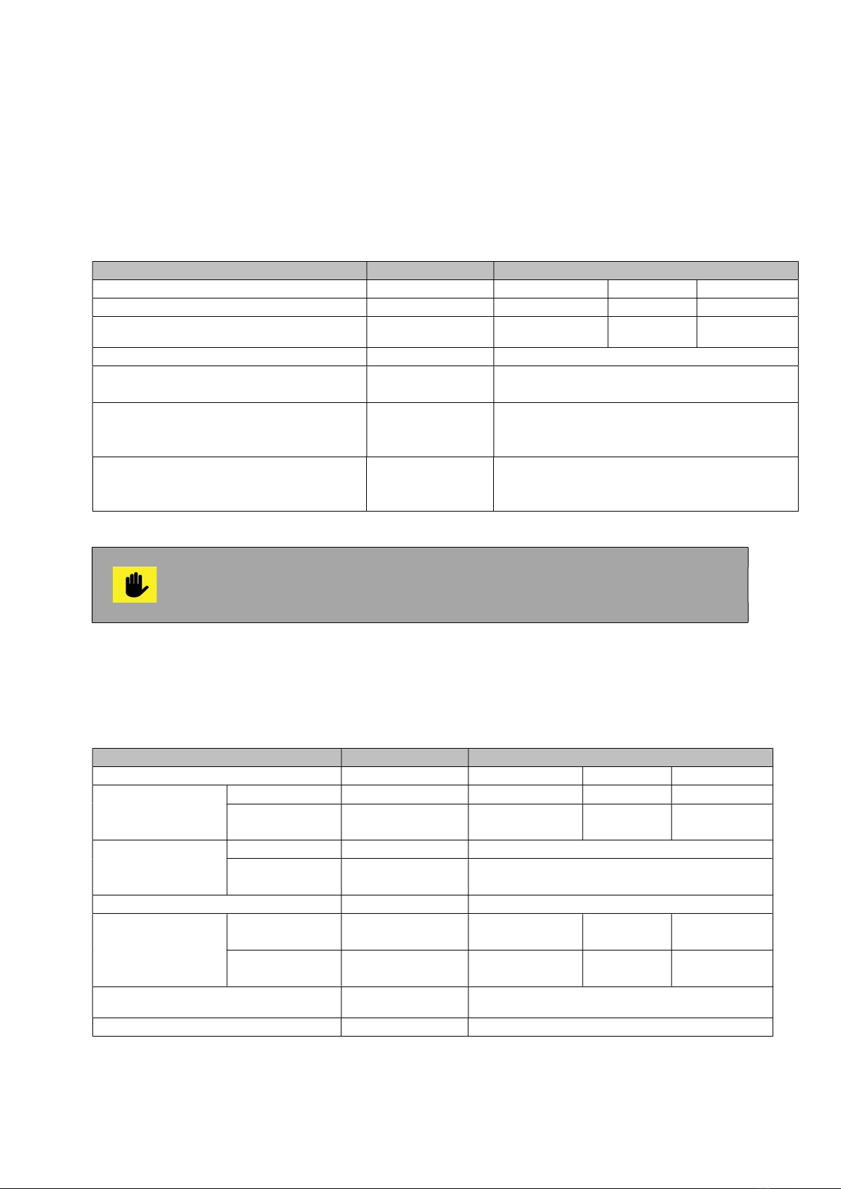
Table 3.1. Technical parameters of the automated pellet burner from series „GP xx sc”,
operating with wood pellets.
PARAMETER DIMENSION VALUE
Burner model - GP 20_18 sc GP 25 sc
GP 32 sc
Nominal heating output kW 18 25 32
Heating output adjustment range kW 7-18 7-25 10-32
Used fuel - Wood pellets
Wood pellets classes according to
standard EN ISO 17225-2:2014
- A1, A2 and B
Used pellets categories (according to
the manufacture company’s
classification)
- A, AB, B, BC and C
Wastes after complete fuel burning Ash
The quantity depends on the pellets ash
content and on the burner’s operation
mode
The automated pellet burner from series „GP xx sc” is designated for utilization of
wood pellets complying with the classification of standard EN ISO 17225-2:2014,
classes A1, A2 and B, and also with the developed classification by the
manufacture company.
The dimensions and technical parameters of the automated pellet burner from series „GP xx
sc” are presented in Table 3.2.
Table 3.2. Dimensions and technical parameters of an automated pellet burner from series
„GP xx sc”.
PARAMETER DIMENSION VALUE
Model - GP 20_18 sc GP 25 sc
GP 32 sc
Weight
Main module kg 20 20
20
Fuel feeding
auger
kg 8.5 8.5 8.5
Overall
dimensions
(WхLхH)
Main module mm 250х705х488
Fuel feeding
auger mm 184x1520x107
Power supply voltage - L1, N, PE, 50Hz; 230VAC;
Electrical
consumption
In nominal
mode
A 0.2 0.2 0.2
In ignition
mode
A 4.5 4.5 4.5
Electrical power W <100
+1100
(with ignition)
Electrical protection - IP20
Pellet burner GP xx sc 8
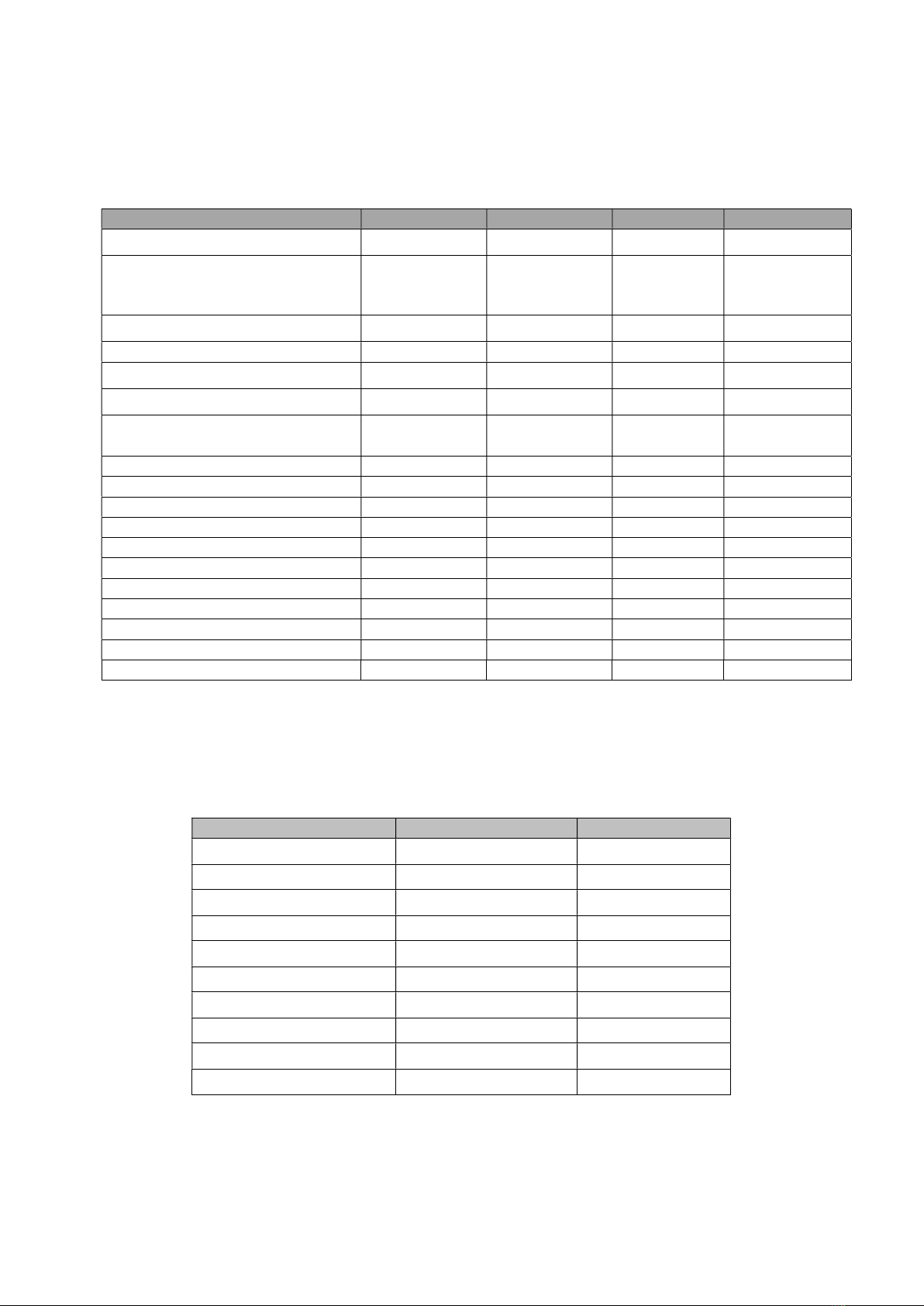
With the adoption of the new standard for wood pellets (EN ISO 17225-2) in 2014 there are
introduced a new classes for wood pellets used in domestic heating boilers (Table 3.3.).
Table 3.3. Standard for wood pellets EN ISO 17225-2:2014.
Wood pellets classification, developed and applied by the manufacture company, depending
on their physical properties is presented in Table 3.4.
Table 3.4. Wood pellets classification, developed and applied by the manufacture company,
depending on their physical properties.
PELLETS CATEGORY A
D
DU
A %6.0
d
A %0.97
DU
AB %6.0
d
A %0.97
DU
B %0.16.0 d
A %0.97
DU
BC %0.16.0 d
A %0.97
DU
C %0.2%0.1 d
A %0.97
DU
CD %0.2%0.1 d
A %0.97
DU
D %0.3%0.2 d
A %0.97
DU
DE %0.3%0.2 d
A %0.97
DU
E %0.3
d
A %0.97
DU
EF %0.3
d
A %0.97
DU
where:
Ad - ash content of dry mass, %;
DU - mechanical resistance, %.
Parameter Dimension Class A1 Class A2 Class B
Length (L) mm 3,15 ≤ L≤ 40 3,15 ≤ L≤ 40
3,15 ≤ L≤ 40
Diameter (D) mm 6±1
8±1
6±1
8±1
6±1
8±1
Moisture (М) % < 10 < 10 < 10
Ash (A), dry % < 0,7 < 1,2 < 2,0
Buck density (BD) kg/m
3
> 600 > 600 > 600
Mechanical durability (DU) % > 97.5 > 97.5 > 96.5
Net caloricity (Q) MJ/kg
kWh/kg
> 16,5
> 4.6
> 16,5
> 4.6
> 16,5
> 4.6
Chlorine Cl % < 0,02 < 0,02 < 0,03
Nitrogen (N) % < 0,3 < 0,5 < 1,0
Sulphur (S) % < 0,04 < 0,05 < 0,05
Arsenic (As) mg/kg < 1 < 1 < 1
Cadmium (Cd) mg/kg < 0.5 < 0.5 < 0.5
Chromium (Cr) mg/kg < 10 < 10 < 10
Copper (Cu) mg/kg < 10 < 10 < 10
Lead (Pb) mg/kg < 10 < 10 < 10
Mercury (Hg) mg/kg < 0.1 < 0.1 < 0.1
Nickel (Ni) mg/kg < 10 < 10 < 10
Zinc (Zn) mg/kg < 100 < 100 < 100

Pellet burner GP xx sc 9
4. CONSTRUCTION DESCRIPTION OF THE PELLET BURNER “GP XX SC”.
4.1. GENERAL CONDITIONS.
The main part from the construction of a pellet burner from series „GP xx sc” is the main
module, which consists of:
Combustion chamber, which forms conditions for optimal burning process and is
made of high quality stainless steel;
Combustion chamber’s fire-grate;
System for automatic cleaning of the combustion chamber;
Air distribution tract, which provides equal firing air feeding and also cooling of the
burner’s components;
Heating element, which ignites the fuel, positioned under the tilted part of the
combustion chamber’s fire-grate;
Firing air feeding fan, equipped with sensor for controlling of the rotation frequency
and also for adjustments;
Photic sensor, which monitors the burning process, mounted on the burner’s side and
with availability for easy cleaning;
Emergency temperature sensor for protection from the so called “back fire” in the
main module’s pellets feeding pipe;
Control module, which monitors and manages the burner’s operation;
Display panel with keyboard, which visualizes the burner’s operation mode and is
used to perform the necessary adjustments;
Connector for the fuel transport auger, used to supply the auger with electrical power;
Flexible pipe, made of special transparent high temperature resistant material (in
case of fire it does not separate toxic substances), used to connect the auger and the
main module of the burner.
Figure 4.1 presents a view of the main modules of a pellet burner from series „GP xx sc”.
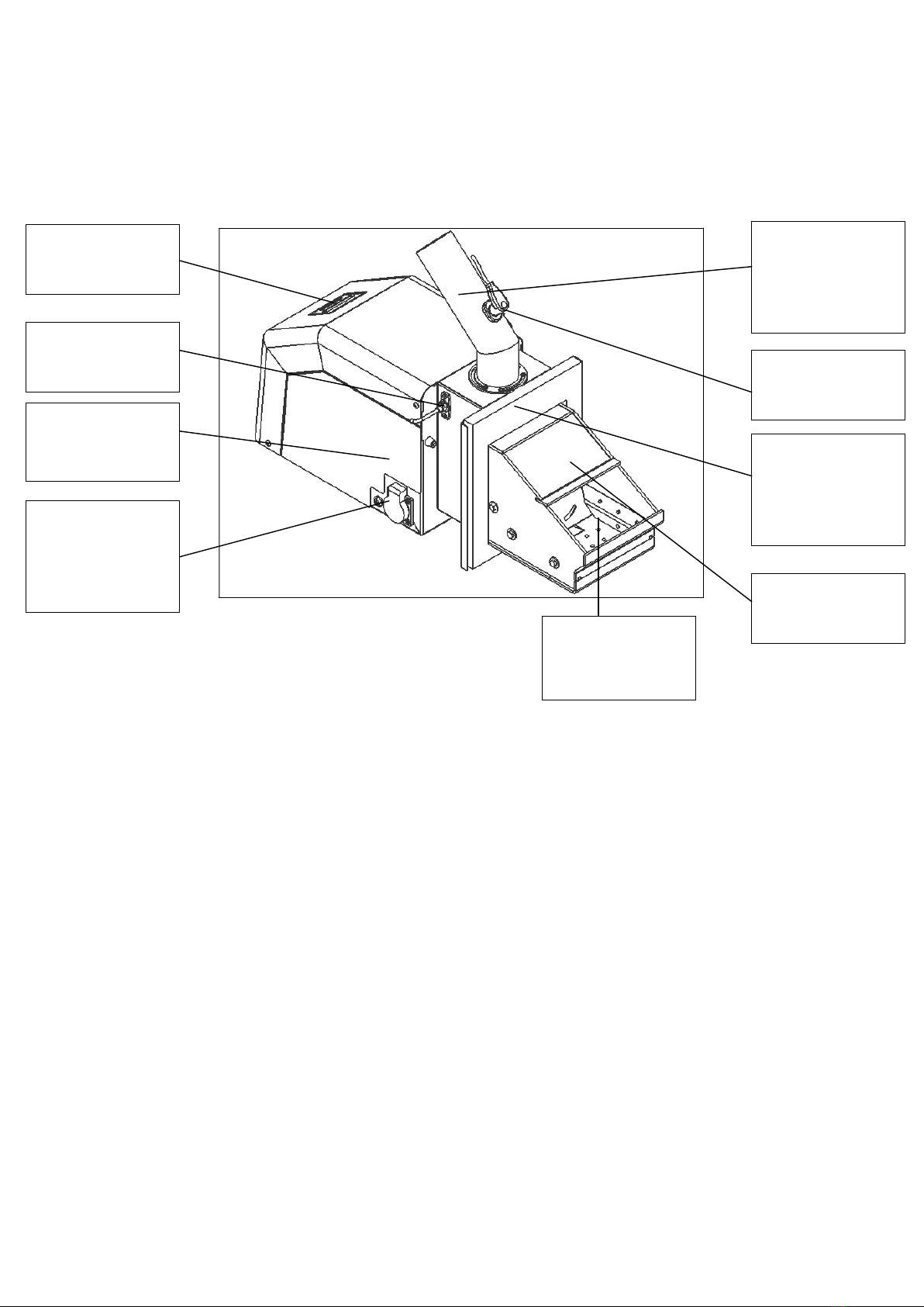
Pellet burner GP xx sc 10
Figure 4.1. View of the main module of a pellet burner from series „GP xx sc”.
Pellets feeding
inlet pipe to
combustion
chamber
Flange for
mounting of the
main module to
an appliance
Combustion
chamber
Emergency
sensor for “back
fire
”
protection
Main module
housing
Combustion
chamber’s
fire-grate
Socket for power
supply and
control of the
transport auger
Photic sensor
Interface panel
(display +
keyboard
)

Pellet burner GP xx sc 11
5. MOUNTING AND INSTALLATION OF THE PELLET BURNER.
5.1. MAIN REQUIREMENTS FOR INSTALLATION OF A PELLET BURNER „GP XX
SC”.
The following requirements must be observed during installation of a pellet burner from
series „GP xx sc”:
The burner must be positioned in a way providing enough free space for its cleaning
and maintenance;
The burner must be mounted to appliance (hot water boiler, or other heat energy
consumer) in a way providing availability for easy maintenance and cleaning of the
appliance;
It is not allowed to mount the burner to appliance, which has been installed in living
premises, including corridors;
The installation and mounting of the burner to appliance must be performed only by a
qualified technician;
The installation and maintenance of the automated pellet burner must be performed
by specialized companies which have acquired legal rights for such activities;
The automated pellet burner from series „GP xx sc” must be connected to the
electrical supply installation only by an authorized electrical technician;
Before initiation of the burner to operation, the heat energy consuming appliance’s
operational condition must be checked;
The burner attendance must be performed only by adult persons, which are well
familiar with the appliance’s manual for operation.
The mounting of the burner to a boiler (consumer-appliance) can be performed
through bolts (or studs) and nuts. The tightening of the burner has to be
performed by a tool (for example wrench). It is not allowed to fix it through
handles or others. The fixing and dismounting operations of the burner must be
performed by a qualified person equipped with proper tools.
5.2. INSTALLATION OF THE PELLET BURNER.
The installation of the pellet burner from series „GP xx sc” to appliance requires preliminary
prepared technical project, complying with the acting provisions and regulations:
In case the consuming appliance is a hot water boiler, then the requirements
presented in standard EN 303-5:2012 - "Heating boilers. Part 5: Heating boilers for
solid fuels, manually and automatically stoked nominal heat output of up to 500 kW.
Terminology, requirements, testing and marking.;
In case the heat energy consuming appliance is not a hot water boiler, then the
requirements presented in the relevant standards for such type of appliances must be
observed;
Fire safety provisions;
About the electrical supply network – EN 60335-1/1997 – “Securing of electrical
domestic appliances”.
When installing a pellet burner to a hot water boiler, please observe the relevant
chimney draught requirements, presented in the boiler’s technical data sheet.

Pellet burner GP xx sc 12
5.3. OVERALL DIMENSIONS OF THE BURNER’S MAIN MODULE.
Figure 5.1 and 5.2 present the overall dimensions of the burner’s main module, which have
to be taken in mind during the mounting and installation of the appliance.
Figure 5.1. Main module’s overall dimensions of a pellet burner from series „GP xx sc”.
Figure 5.2. Overall dimensions of the burner’s main module.

Pellet burner GP xx sc 13
5.4. POSITIONING AND MOUNTING OF THE BURNER’S MODULES.
The main module of a pellet burner from series „GP xx sc” has to be mounted horizontally to
the appliance, which will consume the heat energy generated by the fuel burning. Depending
on the appliance type a technical evaluation has to be performed in advance, regarding the
burner’s main module position, in order to achieve reliable operation, easy cleaning,
maintenance and servicing.
The burner’s main module has to be mounted to the heat energy consuming appliance by
using the attached sealing. The fuel transport auger has to be positioned near to the burner,
in order to ensure the connection between it and the main module through the flexible tube,
through which the fuel transits. It is also recommended that the tilting angle between the
transport auger and the horizontal plane is fixed to 45o, which will provide optimal operation
of the auger’s electric motor and of the burning process.
In order to ensure optimal operational conditions of the fuel transport auger it is
recommended to use a pellet hopper – produced by the burner’s
manufacture company. This hopper is not included in the standard delivery kit of
the pellet burners from series „GP xx sc”.
Change of the auger’s tilting angle leads to changes in the fuel consumption and
respectively to the burner’s heating output:
- Decreasing the auger’s tilting angle leads to increased fuel consumption,
respectively to increased heating output;
- Increasing the auger’s tilting angle leads to decreased fuel consumption,
respectively to decreased heating output.
Figure 5.3 presents a scheme for installation and positioning of the fuel transport auger.
Figure 5.3. Scheme for installation and positioning of the fuel feeding auger.
The auger on the scheme is equipped with metal support bar, which is optional
equipment to the burner’s delivery kit. The auger’s axis has to be positioned at
45o angle relative to the horizontal plane.
45
о
Fuel Hopper”

Pellet burner GP xx sc 14
5.5. INFORMATION ABOUT INSTALLATION AVAILABILITIES OF PELLET BURNER
„GP XX SC” AND ITS CO-OPERATION WITH HOT WATER BOILERS.
The automated pellet burner from series „GP xx sc” is a standalone module (requires power
supply and signal – assignment for operation), which can be mounted to a heat energy
consuming appliance. The practice shows that the heat energy consuming appliance is most
frequently a hot water boiler, used in local heating installation. The manufacture company
has accomplished continues tests for compatibility, reliability and efficiency of the burner in
co-operation with series of popular hot water boilers. Depending on the hot water boiler
model additional transition modules and components might be used, in order to improve the
system’s performance that is consisting of a pellet burner and a hot water boiler, and to
increase its efficiency and reliability.

Pellet burner GP xx sc 15
6. INITIATION TO OPERATION OF THE PELLET BURNER „GP XX SC”.
The automated modulating pellet burner from series „GP xx sc” has to be initiated
to operation only by a specialized company, authorized for such activities.
6.1. MAIN REQUIREMENTS ABOUT THE USED FUEL TYPES.
During initiation to operation of a pellet burner from series „GP xx sc” the following main
requirements about the used fuel types must be observed:
To achieve complete fuel burning it is necessary to use only dry fuels. It is
recommended to store the fuel in dry and ventilated premises;
It is forbidden to store the fuel next to the appliance to which the burner is mounted or
at distance less than 400 mm from it;
The optimal recommended distance between the appliance (to which the pellet
burner is mounted) and the fuel is at least 1000 mm. It is preferable to store the fuel in
a neighbor room;
When installing the pellet burner from series „GP xx sc” to the desired appliance and
when storing the fuel, all fire safety requirements must be observed. It is
recommended to position a fire-extinguisher at an easy access and safe place near
the boiler.
6.2. INITIATION TO OPERATION OF A PELLET BURNER „GP XX SC”.
When initiating to operation a pellet burner from series „GP xx sc”, the following main
requirements must be observed:
Maintenance and attendance of the burner must be performed in accordance to the
manual for maintenance and operation;
The operation mode of the system: a pellet burner from series „GP xx sc” and a heat
energy consumer, must provide minimum under-pressure (pressure lower than the
atmosphere’s) in the appliance’s combustion chamber, within range 5 – 20Pa;
Non-compliance with the above requirement might lead to emergency modes or
to ineffective operation of the burner. The value of the under-pressure in the heat
energy consuming appliance’s combustion chamber depends on the chimney
draught and on other modules (for example a flue gas extraction fan). Operation
modes, non-complying with this requirement might be ascertained through the
temperature value indicated by the reversible temperature sticker.
Any interference to the operation of the appliance that might lead to risks for the
health of the servicing/attending personal or to other indirectly linked people is strictly
forbidden;
During operation the burner has to be periodically checked by the user/attending
staff;
The user must not perform any repairs over the system’s modules. If a failure or a
problem occurs during operation then the users must ask for technical assistance by
a servicing company;
It is forbidden to increase the burner’s heating output above the nominal output;
The ash residues from the burning process must be gathered in proper fire-proof
container and after cooling to ambient temperature it has to be dumped to proper for
the purpose places.

Pellet burner GP xx sc 16
6.2.1. INTERFACE PANEL OF AN AUTOMATED PELLET BURNER “GP XX SC”.
Figure 6.1 presents a view of an interface control panel equipped with display and keyboard,
used to manage the automated pellet burner from series „GP xx sc”.
Figure 6.1. Interface panel of a pellet burner from series „GP xx sc”.
Components of the interface control panel and their functions:
Button “ S ” – is used to choose a submenu and to confirm the performed
adjustments;
Button “ - ” – is used to decrease a currently changing parameter value from the
controller’s menu;
Button “ + ” - is used to increase a currently changing parameter value from the
controller’s menu;
Button “ESC” – is used to cancel a change of chosen parameter from the controller’s
menu and to exit a chosen operational menu.
The above presented buttons of the burner’s interface control panel might have
another function, which will be described on the display panel.
.
6.2.2. CONNECTING AND POWER SUPPLYING OF THE BURNER.
All activities over the burner’s electrical installation, adjustments requiring
dismounting of cover panels or other components, which protect from direct
contact with electrical parts, must be performed only by qualified staff.
The burner must be connected to the electrical installation of the appliance to which it is
mounted, by observing all technical safety rules. Use the power supply cable and the
attached wiring diagram for connecting to power supply voltage and to the burner’s operation
control module.
The fuel feeding auger is mounted to the hopper and is positioned in a way providing the
required fuel feed rate, as it is also filled with fuel.
Button “-” (its function
depends on the chosen
menu)
Button “+” (its function
depends on the chosen
menu)
Button “Escape”
Button “Enter”

Pellet burner GP xx sc 17
The sensitive component of the circulations water temperature sensor has to be mounted in
a sleeve for measuring of the outlet water temperature of the hot water boiler or has to be
screwed in a threaded orifice (depending on the sensor type).
6.2.3. SWITCHING ON THE PELLET BURNER FROM SERIES „GP XX SC”.
The burner switching ON has to be performed through the power supply of the appliance, to
which it is mounted. If the burner has been in operational mode (or in “hot reserve”) but the
power supply has been interrupted, then when the power supply restores the burner will
continue its operation automatically.
In case the appliance to which the burner is mounted is not properly sealed and
the burner is operating, smoking of flue gasses through the unsealed sections is
possible to occur, as well as through the fuel feeding flexible pipe. It is
recommended to seal these sections and to adjust the burner’s heating output in
order to avoid such smoking. The same effect might be monitored during the
transition seasons – autumn and spring, when the natural chimney draught is
decreased due to higher ambient temperatures.
During the burner’s ignition mode the heating elements activate, which are
positioned under the combustion chamber’s fire-grate. This zone is heated to
high temperatures and could be dangerous in case it is touched – manipulations
in the burner’s combustion chamber zone should not be performed. If necessary
to stir (spread) or remove the fuel then proper tools and personal protection
equipment must be used.
When initiating the burner to operation for the first time the auger (fuel feeding)
device must be filled with pellets – this is continues process requiring time.
Therefore the auger must be connected to external power supply, through its
standard plug and to wait until the fuel starts to drop from its top orifice. After that
it must be connected to the power supply socket of the burner’s main module.
The burner’s main module constantly checks if the feeding auger is connected to
its socket and if this condition is not fulfilled the system will transit to emergency
mode, until the auger’s power supply cable is connected properly. After that it is
necessary to restart the burner’s main module in order to transit to normal
operational mode.
If the power supply cable of the transport auger has been disconnected from the
burner’s main module socket (this situation is treated by the controller as an
emergency mode – i.e. there is no motor connected to the socket) and the burner
has been operating at that time, then an emergency mode activates and the
burner operation stops. To reset the alarm it is necessary to connect the auger’s
plug back to the burner’s main module and to switch the burner’s power supply
button to position OFF and then back to ON (restart).
The burner operates through a preliminary set algorithm, which is installed in its
control module. The optimal operation parameters are adjusted in the
manufacture company’s factory and their change is generally not required.

Pellet burner GP xx sc 18
6.2.4. ALGORITHM OF OPERATION OF A PELLET BURNER „GP XX SC”.
The pellet burner starts operation when the following conditions are observed:
The burner’s main module is mounted to the appliance to which it will operate;
Presence of electrical power supply;
Activated start through the display panel;
Installed circulations water temperature sensor – in case such method is used to
regulate the burner’s operational mode;
Lack of emergency signals;
The fuel hopper and the transport auger are filled with fuel.
When the above conditions are fulfilled the control module executes the following algorithm:
Submits power and the external transport auger, the heating element and the firing air
feeding fan switch ON;
After expiry of the preliminary set (by the manufacturer) time, which provides loading
of the combustion chamber with the so called “ignition” fuel doze, the auger’s power
supply cuts off and it stops;
After the photic sensor in the burner registers presence of burning process the
heating elements power supply cuts off. For a defined period of time the burner
reaches the assigned heating output. If the photic sensor does not register a flame
within a set period of time, the controller performs new attempt for ignition through the
above presented algorithm. The ignition attempts are limited to two;
In case of successful fuel ignition the system transits to nominal operation mode of
the burner, which is realized through periodical fuel feeding and pauses for burning.
The times for fuel feeding and pauses are adjusted in the control module’s software.
The burner heating output can be changed by selecting one of its output levels;
The maximum heating output level - 5-th of the burner is not recommended. This
level should be chosen only in cases when the used fuel type is with lower
caloricity value or when higher heating output is temporarily needed. The
recommended output levels are from 1 to 4, as normally level 4 reaches the
nominal heating output.
A NTC sensor is used as control device for determining of the circulations water
operational temperature:
- When the assignment is nearly reached the burner’s control module
decreases its heating output (so called modulation of the operation mode);
- If the circulations water temperature decreases the burner restores its
heating output.
If the operation signal drops out during operation (for example by room thermostat),
then the burner will switch off through the above presented algorithm;
If during rest the operation assignment changes and it receives signal for operation,
then it will start operation through the above presented algorithm. The same condition
is valid in case the circulations water temperature is lower than the adjusted in the
burner’s control module;
If the fuel does not ignite within the first attempt a new attempt is automatically
performed, as the ignition attempts are maximum two (defined by the manufacturer).
In case of second unsuccessful ignition there is possibility of presence of unburned
fuel over the main module’s fire-grate. It is necessary to find and remove the reason
for unsuccessful ignition and also to clean the combustion chamber’s fire-grate from
the fuel residues;

Pellet burner GP xx sc 19
If the gathered fuel over the burner’s fire-grate has not been removed, after
successful ignition (for example after restarting the burner) it might lead to difficult
firing of relatively larger amount of fuel, to separation of inflamed gasses and
respectively to their explosive ignition. Such explosive ignitions might lead to
mechanical damages of the appliance, to which the burner’s main module is
mounted.
If the photic sensor does not register a burning process during operation, then the
fuel ignition algorithm starts again;
If two unsuccessful attempts for ignition have been performed, for example in case
the fuel has been depleted, then the burner stops the main algorithm and transits to
emergency mode, which is shown on the display panel and should be considered as
a necessity for intervention by the user, as the failure reason requires removal. After
the failure has been removed the new start has to be performed through consecutive
switching OFF and then back ON (restarting) of the appliance’s common power
supply, to which the burner is also connected.
Before starting the burner’s fire-grate has to be checked for presence of
unburned fuel and ash. If so, the fuel and the ash residues have to be removed.
If the power supply has been interrupted the burner will start automatically when the
supply restores.
During operation the burner might transit to final combustion and blowing, if the
relevant option for cleaning during operation is switched ON – parameter
“Max.comb.time”. This parameter is in “Advance menu”, as the access to it is
password protected.
6.2.5. OPERATIONAL PARAMETERS FOR ADJUSTMENT OF A PELLET BURNER „GP
XX SC”.
The operational parameters are preliminary set in the burner’s control module by the
manufacturer, as the user and/or other attending staff are not required to perform changes.
In order to achieve optimal and economic operational conditions of the burner it is necessary
to assign such heating output that will provide optimal operation and low fuel consumption.
The practice shows that the constant operation of the burner provides optimal fuel
consumption.
The controller’s display panel and the keyboard are used to show information about the
burner’s operation mode. The operational parameters adjustments have to be performed by
trained specialist.

Pellet burner GP xx sc 20
6.2.6. DESCRIPTION OF THE PRIMARY MENU, THE METHODS OF STARTING AND
OPERATIONAL PARAMETERS ADJUSTMENT OF A PELLET BURNER „GP XX
SC”.
Figure 6.2. Starting display, shown when starting an automated pellet burner from series
„GP xx sc”.
After the software has been loaded (after a few seconds) the display panel shows a question:
whether to start the burner? (Activate?):
Figure 6.3. Menu for starting a pellet burner from series „GP xx sc”, through inviting question.
To start the burner’s operation press the button “S”, as presented on the figure.
After starting the burner’s operation a message is shown on the display panel, as presented
on the next figure.
S _ + ESC
Activate?
ENTER
S _ + ESC
GREEN ecoTHERM
V2.3 2E
Version of the
software for
management of the
burner
This manual suits for next models
3
Table of contents
Popular Burner manuals by other brands

Enertech
Enertech Nu-Way NG Series Installation & maintenance manual

Cook's Companion
Cook's Companion CCNIB/B414124 Care and use instructions

Bull
Bull 60018 owner's manual

Riello
Riello RG2D Installation, use and maintenance instructions

Octagon
Octagon bio 3 user guide

Riello Burners
Riello Burners RLS 300/BP MX Installation, use and maintenance instructions


Ooni
Ooni Karu 12 manual

CIB UNIGAS
CIB UNIGAS Idea Series Manual of installation - use - maintenance

Ecoflam
Ecoflam BLU 1700.1 PR manual

CIB UNIGAS
CIB UNIGAS N1060A Manual of installation - use - maintenance

ENJOYABLE WARMTH
ENJOYABLE WARMTH SF Series owner's manual

Riello
Riello 3898350 Installation, use and maintenance instructions