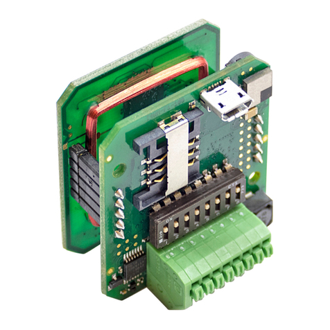
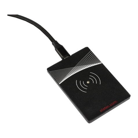
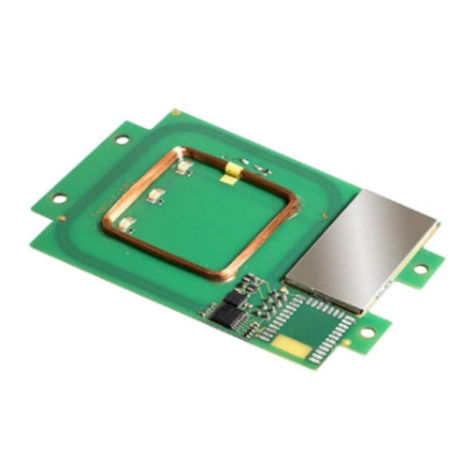
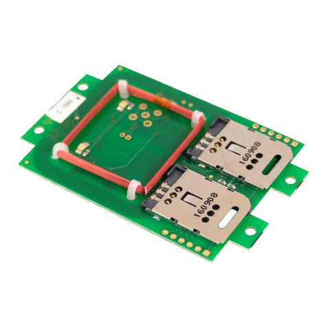
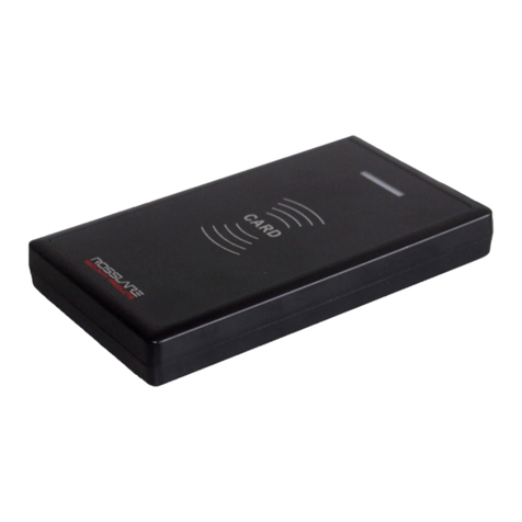
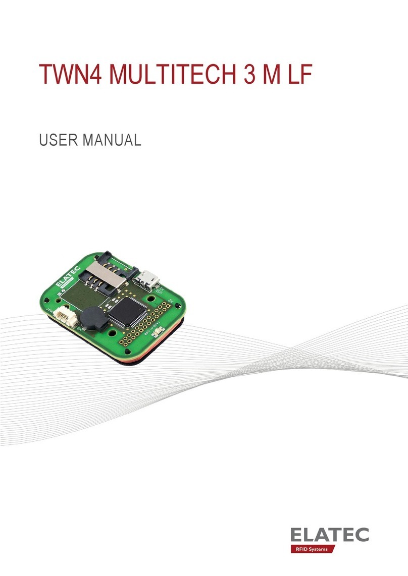
Elatec TWN3 MIFARE User manual

Transponder Reader
TWN3
Technical Manual
Doc.-Rev. 1.07

Elatec GmbH
Page 2 of 50
Content
1. Introduction..................................................................................................................... 4
2. Functional Overview....................................................................................................... 4
3. Modes of Operation......................................................................................................... 5
3.1
USB-Device .............................................................................................................................. 6
3.1.1
Keyboard Emulation (USB HID Device).........................................................................................6
3.1.2
Emulating a Virtual Serial Port........................................................................................................6
3.2
V24-Device............................................................................................................................... 6
3.2.1
Serial Communication Parameters ...................................................................................................6
3.2.2
Pin Assignment ................................................................................................................................7
4. Installation ...................................................................................................................... 7
4.1
V24-Device............................................................................................................................... 7
4.2
USB-Device (Keyboard Emulation) ...................................................................................... 8
4.3
USB-Device (Virtual Serial Port) .......................................................................................... 9
5. Configuration ................................................................................................................ 11
5.1
Entering the Configuration Mode....................................................................................... 11
5.2
Writing a Configuration to a TWN3 Device ...................................................................... 12
5.3
Resuming Normal Operation............................................................................................... 13
5.4
Selecting Mode of Operation ............................................................................................... 14
5.5
Setting Up the Keyboard Emulation................................................................................... 15
5.5.1
Table of Scan Codes ......................................................................................................................15
5.5.2
Sending ALT Codes.......................................................................................................................17
5.5.3
Key Repeat Rate ............................................................................................................................17
5.6
Installing Scripts ................................................................................................................... 18
5.7
Miscellaneous Settings.......................................................................................................... 19
5.8
Updating the Firmware........................................................................................................ 20
5.9
Preferences ............................................................................................................................ 21
5.10
Export and Import of Configurations............................................................................. 22
5.11
Installing USB-Drivers for Configuration...................................................................... 23
6. Transparent Mode......................................................................................................... 24
6.1
HID Prox Transparent Protocol.......................................................................................... 25
6.2
IndiTag Transparent Protocol............................................................................................. 25
7. Scripting ........................................................................................................................ 26
7.1
Language Description........................................................................................................... 26
7.1.1
Source Code...................................................................................................................................26
7.1.2
Comments ......................................................................................................................................26
7.1.3
Case Sensitivity..............................................................................................................................26
7.1.4
Preprocessor Directives .................................................................................................................26
7.1.4.1
#include Directive......................................................................................................................27
7.1.5
Functions........................................................................................................................................27
7.1.5.1
Return Values.............................................................................................................................27
7.1.5.2
Arguments..................................................................................................................................27

Elatec GmbH
Page 3 of 50
7.1.5.3
System Functions .......................................................................................................................27
7.1.5.4
Function main ............................................................................................................................28
7.1.6
Statements......................................................................................................................................28
7.1.6.1
if Statement ................................................................................................................................28
7.1.6.2
if else Statement.........................................................................................................................28
7.1.6.3
while Statement..........................................................................................................................28
7.1.6.4
do while Statement.....................................................................................................................28
7.1.6.5
for Statement..............................................................................................................................29
7.1.6.6
switch Statement ........................................................................................................................29
7.1.6.7
break Statement..........................................................................................................................29
7.1.6.8
continue Statement.....................................................................................................................29
7.1.6.9
return Statement .........................................................................................................................30
7.1.6.10
goto Statement .......................................................................................................................30
7.1.6.11
Labels.....................................................................................................................................30
7.1.6.12
Empty Statement ....................................................................................................................30
7.1.7
Storage Types ................................................................................................................................30
7.1.8
Storage Classes ..............................................................................................................................31
7.1.8.1
const...........................................................................................................................................31
7.1.8.2
secret..........................................................................................................................................31
7.1.9
Operators .......................................................................................................................................32
7.2
Runtime Environment.......................................................................................................... 33
7.2.1
Include File ....................................................................................................................................33
7.2.2
Basic Definitions............................................................................................................................33
7.2.3
Bit Fields........................................................................................................................................33
7.2.4
Startup Condition...........................................................................................................................33
7.2.5
System Function Calls....................................................................................................................34
7.2.5.1
Transponder Operations.............................................................................................................34
7.2.5.1.1
Generally Available Transponder Operations .....................................................................35
7.2.5.1.2
Multi125-Specific Transponder Operations........................................................................36
7.2.5.1.3
Mifare- and MultiISO-Specific Transponder Operations....................................................37
7.2.5.1.4
Legic Specific Operations ...................................................................................................38
7.2.5.1.5
HID iClass Specific Operations ..........................................................................................39
7.2.5.2
Functions for Host Communication ...........................................................................................40
7.2.5.3
Accessing LEDs.........................................................................................................................42
7.2.5.4
Accessing the Beeper .................................................................................................................43
7.2.5.5
Bit Operations............................................................................................................................43
7.2.5.6
Byte Operations .........................................................................................................................45
7.2.5.7
Timer Operations .......................................................................................................................46
7.2.5.8
Retrieving System Information ..................................................................................................47
7.2.5.9
Miscellaneous ............................................................................................................................47
8. Firmware History.......................................................................................................... 48
9. Technical Data .............................................................................................................. 48
10. Regulatory Information ................................................................................................ 49
10.1
CE Declaration of Conformity......................................................................................... 49
10.2
FCC Statement .................................................................................................................. 49
10.3
CI (Canada Industry) Statement ..................................................................................... 50
11. Trademarks.................................................................................................................... 50
Elatec GmbH
Page 4 of 50
1. Introduction
This document is the reference guide for the transponder reader family TWN3.
Note:
In order to use the functionality, which is described in this document, your TWN3 reader needs
a firmware version V4.00 or above. The latest version of the firmware is part of the developer
pack. Please revere to section “Updating the Firmware”, if you would like to update the
firmware.
2. Functional Overview
Here is a block diagram of the basic functional components of a TWN3 transponder reader:
Multi125 Mifare HID Prox HID iClass
Transponder Family Depending On Type of Devi e
Transparent Communi ation S ript Controlled Operation
Physi al COM Port Virtual COM Port Keyboard
Emulation
USB-Interfa eV24-Interfa e
TWN3 Transponder Reader
Legi IndiTag MultiISO

Elatec GmbH
Page 5 of 50
Let’s take a more detailed view:
The diagram below is showing the functional units and how they can be configured:
V24-
Interfa e
S ripting
Engine
Multi125
Mifare
HID Prox
HID iClass
Legi
Transparent
Communi ation
Config
Mode
Command
for Config
Mode
TWNConfig
Sele ted by
Cable
TWNConfig
S an ode
Translation
Table
USB Virtual
COM Port
USB
Keyboard
Emulation
TWNConfig TWNConfig TWN3
Devi e Type
IndiTag
MultiISO
3. Modes of Operation
The transponder reader TWN3 can be ordered in several hardware configurations:
•Support for the specific transponder family (Multi125, Mifare, HID Prox, HID iClass, Legic,
IndiTag, MultiISO)
•Physical type of connection (type of cable) to the host computer: USB or V24, DSUB25,
DSUB9 or PS/2
Many other configurations can be done by the system integrator:
•Type of USB mode (USB devices only)
•Behavior of keyboard emulation
•Scripting mode

Elatec GmbH
Page 6 of 50
3.1 USB-Device
A TWN3 USB reader is capable of supporting several modes of operation:
3.1.1 Keyboard Emulation (USB HID Device)
This is the default mode for USB devices. No drivers are required for running the device in a typical
environment like Windows XP or Linux. Any output from the TWN3 transponder reader to the host is
sent like keyboard input from a user. Therefore, any characters are displayed at the current position of
the cursor on the screen of the computer.
Please be aware, that the communication between TWN3 device and host computer is unidirectional.
This means, there is no possibility to send data from the host to the TWN3 device. In situations where
this is required, we recommend the emulation of a serial port.
3.1.2 Emulating a Virtual Serial Port
Optionally, a USB device can be configured to emulate a virtual serial port. This mode of operation is to
be preferred, if a direct communication between application and TWN3 transponder reader is required.
This mode also enables a bidirectional communication between .
The communication protocol is identical to the version of TWN3 reader with a physical V24 interface.
3.2 V24-Device
3.2.1 Serial Communication Parameters
Parameter Value
Baudrate 9600 Baud
Databits 8
Parity None
(1)
Stopbits 1
Handshake None
Connector DSUB25 or DSUB9 or PS/2
(1)
TWN3 Multi125 in transparent mode is using even parity,
which is the native setup for the T4 transponder reader
family.

Elatec GmbH
Page 7 of 50
3.2.2 Pin Assignment
Following pin assignment for the DSUB25 plug:
Pin Signal
2 RxD from host
3 TxD to host
7 Signal ground
24 5V power supply from the host
Following pin assignment for the DSUB9 plug:
Pin Signal
3 RxD from host
2 TxD to host
5 Signal ground
9 5V power supply from the host
Following pin assignment for the PS/2 plug:
Pin Signal
6 RxD from host
2 TxD to host
3 Signal ground
4 5V power supply from the host
4. Installation
4.1 V24-Device
Installing a TWN3 reader with a serial port requires an additional power supply, which is not standard
for usual PCs. On the other hand, many devices do supply the 5V on a rarely used pin of the serial
connector. Please contact your supplier for a specific solution.
The installation of the reader is as simple as connecting a USB device to a host.

Elatec GmbH
Page 8 of 50
4.2 USB-Device (Keyboard Emulation)
Installing a TWN3 reader emulating a keyboard is rather simple due to the fact, that drivers do come
with the operating system. Therefore, the device simply can be connected to the host computer and
can be immediately used.

Elatec GmbH
Page 9 of 50
4.3 USB-Device (Virtual Serial Port)
In order to install a TWN3 reader, which emulates a virtual serial port under Windows XP, keep the
drivers nearby and follow these steps:
•Plug in the TWN3 reader into your host computer. The following screen should appear (in your
native language)
Select to install the software from a specific source.
•The following screen should appear:
Select the directory, where the drivers reside and click continue. The drivers will be installed
now.
•After installation, the following screen should appear:

Elatec GmbH
Page 10 of 50
The installation is now completed. In order to find the serial communication port, which is emulated by
the TWN3 transponder reader, you may take a look into the device manager:
In this example, we find the TWN3 reader at COM7.
Depending on the further configuration of the device, you may now test the TWN3 transponder reader
with a normal terminal program.

Elatec GmbH
Page 11 of 50
5. Configuration
In order to configure a TWN3 transponder reader, the program TWNConfig.exe is required.
Configuration is supported under Windows XP or Windows Vista. During configuration, a TWN3
transponder reader is switched into configuration mode. In this mode the entire setup of the device can
be done. Configuration is possible both for V24 and USB devices.
Note:
Please do not connect more than one TWN3 device at a time to your computer during the usage
of TWNConfig. This ensures the knowledge about the TWN3 device which is actually to be
configured.
5.1 Entering the Configuration Mode
Assuming, that the TWN3 transponder reader is already connected to the host computer, start the
program TWNConfig.exe. The following screen will appear:
Depending on the physical interface of the TWN3 transponder reader, choose the appropriate port in
the top left combo box. Click the “Connect”-button.

Elatec GmbH
Page 12 of 50
TWNConfig is searching and connecting to a TWN3 device. You are now ready to do the required
configurations on the device.
Note:
If you are configuring a USB device the first time, you have to install the appropriate
configuration drivers. Please refer to “Installing USB-Drivers for Configuration”.
5.2 Writing a Configuration to a TWN3 Device
Once a configuration has been set up completely (either via importing a configuration or manually via
the tab folders), the configuration can be written back to the TWN3 device. This will save the
configuration permanently in the TWN3 device. In order to do that, click the button “Write Config”.

Elatec GmbH
Page 13 of 50
5.3 Resuming Normal Operation
In order to leave the configuration mode of the TWN3 device and resume to normal operation click the
“Restart” button.
Note:
Disconnecting the device from the host or a power cycle will keep the device in configuration
mode!

Elatec GmbH
Page 14 of 50
5.4 Selecting Mode of Operation
In the tab folder “Mode of Operation” you select the basic mode in which the TWN3 device operates.
This setup is used both for USB and V24 devices:
Mode USB Device V24 Device
1 Intelligent Virtual COM Port:
Run a script on the TWN3 device
(“intelligent”) and emulate a COM port
Intelligent Operation:
Run a script on the TWN3 device
(“intelligent”)
2 Intelligent Keyboard Emulation:
Run a script on the TWN3 device
(“intelligent”) and emulate a keyboard
Intelligent Operation:
Identical to V24 Mode 1
3 Transparent Virtual COM Port:
Establish a direct link between the virtual
COM port and the internal transponder
reading module.
Transparent Operation
Establish a direct link between the serial
port and the internal transponder reading
module.

Elatec GmbH
Page 15 of 50
5.5 Setting Up the Keyboard Emulation
5.5.1 Table of Scan Codes
This tab folder enables you to change the scan codes of the keyboard emulation, which are sent to the
host for a specific character. The default setup of the device already contains the mainly used
characters ‘0’ – ‘9’, ‘A’ – ‘F’ and the carriage return. This enable the reader to send any hex number
and an ENTER to the host computer.
There are some reasons, why you may want to change the existing setup:
•You need a setup for a specific country, where the key layout of a keyboard is different from
the default one.
•You need some additional keys in order to achieve your specific format to be sent to the host.
This might be an additional space or a tab instead of return.

Elatec GmbH
Page 16 of 50
In order to do this, you may double-click on an existing entry in the table or specify a new entry by
pressing the “Add”-button. In the following dialog you now are able to select the appropriate keys.
Please keep in mind, that the keyboard keys are to be specified in relation to a standard U.S. QUERTY
keyboard, which is shown below:
Source: www.wikipedia.org
Notes:
•A maximum of 48 entries in the scan code table are possible.
•Instead of specifying a key on the keyboard, sending the appropriate ASCII as ALT code
can be configured.

Elatec GmbH
Page 17 of 50
5.5.2 Sending ALT Codes
You may send ALT codes instead of key strokes on a keyboard.
Example:
The character ‘A’ (ASCII code 65) should be sent to the host. Following sequence is executed:
- Press ALT key
- Press key ‘6’ on the numeric keypad
- Release key ‘6’ on the numeric keypad
- Press key ‘5’ on the numeric keypad
- Release key ‘5’ on the numeric keypad
- Release ALT key.
There are advantages and disadvantages in doing so:
Advantages:
•There is no table of keystrokes necessary, which have to be set up. All characters with ASCII
codes in the range from 1 to 255 can be sent.
•No adaptations to different keyboard layouts are necessary.
Disadvantage:
•Some programs do not accept sending ALT codes and react in a complete different way.
•The amount of key strokes is higher. Therefore, the maximum transfer speed is slower.
5.5.3 Key Repeat Rate
The repeat rate, with which key strokes are sent to the host can be adjusted. The time between key
strokes is specified in multiples of milliseconds.

Elatec GmbH
Page 18 of 50
5.6 Installing Scripts
In order to install a script on a TWN3 device, perform following actions:
•Select the tab folder “Scripting”.
•Select a script file (extension “.twn.c”) by clicking the button “Select Script”.
•Click the “Compile Script”. This will start the script compiler.
•If there is an error detected in the script, the line number and type of error will be displayed.
•If the compilation is successful, following screen will appear:

Elatec GmbH
Page 19 of 50
The compiled script is now part of the configuration within TWNConfig. Some additional information is
displayed on how much storage space is occupied by this script. Up to now, the script has not been
saved to the TWN3 device.
5.7 Miscellaneous Settings
Within the tab folder “Misc”, there is only one setting, which influences the behavior on how a carriage
return is transferred to the PC.
The reason for this is that in keyboard emulation, it makes no sense to send a line feed to the host
computer (in fact, there is no key on a keyboard, which does “line feed”). On the other hand, sending a
line feed after a carriage return might appear quite normal in a terminal session via serial interface.
The default value is off.
Conclusions:
•A line feed will only be appended if:
oThis options is selected
oThe device is in intelligent mode (“running a script”)
oThe device is connected via V24 interface or via USB and emulating a virtual serial
port.
•This setting has no influence on any keyboard emulation.
•This setting has no influence in transparent communication.

Elatec GmbH
Page 20 of 50
5.8 Updating the Firmware
In order to update the firmware of a TWN3 device select tab folder “Firmware”.
After any successful connection to a TWN3 device, the current directory will be searched for firmware
images, which are compatible to the connected device. In order to re-program the firmware of a TWN3
device, click the “Program”-button. After successful programming, the following screen should be
displayed:
Notes:
•If programming fails for any reason (blackout or whatever), it is possible to restart the
programming process. The TWN3 device can only be brought back to normal operation
after successful programming of the firmware.
Other manuals for TWN3 MIFARE
4
Table of contents
Other Elatec Card Reader manuals

Elatec
Elatec TWN4 Palon Compact Use and care manual

Elatec
Elatec TWN4 MultiTech 2 HF User manual

Elatec
Elatec TWN4 Palon Compact LEGIC User manual

Elatec
Elatec TWN4 MultiTech 2 HF User manual

Elatec
Elatec TWN4 MultiTech 2 HF User manual

Elatec
Elatec TWN4 MultiTech 2 HF User manual

Elatec
Elatec TWN4 PALON COMPACT LEGIC M User manual

Elatec
Elatec TWN4 MultiTech 2 HF User manual

Elatec
Elatec TWN4 Palon Compact User manual

Elatec
Elatec TWN4 MultiTech 2 HF Use and care manual