elco ECD Series User manual

EL.CO. S.R.L. – ECD - INSTRUCTIONS FOR USE - Ver.01 - 12/22 - PAGE
MODBUS TCP MODBUS RTU
CONVERTER
INSTRUCTIONS FOR USE
Ver. 01 (EN) – 12/22
EL.CO. S.r.l.
Via Lago di Molveno, 20
36015 SCHIO (VI), ITALY
TEL.: +39 0445 661722
FAX: +39 0445 661792
Website: http://www.elco-italy.com
INTRODUCTION
This manual contains the information
necessary for the correct installation and the
instructions for use and maintenance of the
product. It is, therefore, recommended to read
it carefully and preserve it.
This publication is the exclusive property of
EL.CO. S.R.L. that absolutely prohibits it’s
reproduction and disclosure, even partial, unless expressly
authorized.
EL.CO. S.R.L. reserves the right to make aesthetic and
functional changes at any time and without notice.
If a malfunction or failure of the device could create dangerous
or harmful situations for people, things or animals, remember
that the system must be set up with additional devices capable
of guaranteeing safety.
EL.CO. S.R.L. and its legal representatives do not consider
themselves responsible in any way for any damage to people,
things or animals deriving from tampering, improper or
incorrect use or in any case not in compliance with the
characteristics of the device.
1
–
DIMENSIONS (mm)
1.1 – ECD MODULE FOR DIN RAIL ASSEMBLY
DE
w = 22.5 mm
h = 100 mm
d = 113.65 mm
2
-
DEVICE DESCRIPTION
2.1 - GENERAL DESCRIPTION
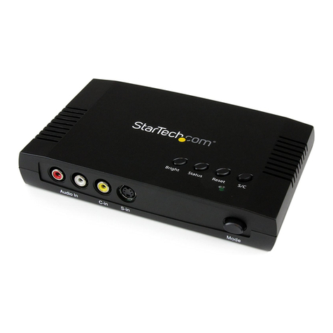
ECD is a TCP modbus to RTU modbus converter. There are two
RTU modbus master ports: one on the screw terminal where up to
256 devices can be connected and one on the bus below the device
where up to 32 devices can be connected.
3
-
SMART
-
CONNECTION
3.1 – CONVERTER FUNCTION
The ECD series involves a strong innovation compared to similar
products. ECD receives a request in TCP modbus and repeats it in
the RTU modbus ports that act as master. ECD has an IP address
and a modbus address. If a request is made via modbus IP, the
device checks the modbus address and, if the address corresponds
to the one programmed, ECD will respond appropriately on the IP
modbus port; otherwise, it replies the packet on the RTU modbus
ports and then replicates any response on the IP modbus port.
3.2 – COMMUNICATION VIA RS485 MODBUS
3.2.1 - DESCRIPTION
The communication speeds adopted for RTU modbus range from
1200 to 38400 baudrates and allow very satisfactory performances,
while remaining well below the limits set by the RS485 standard.
This allows the wiring of the line to be made using a medium quality
twisted and shielded pair: it is sufficient that the total capacitance of
the line does not exceed 200nF.
For the connection of devices with RS485 serial communication via
the bus and the terminal, refer to paragraph 4.4.
To maintain the line in rest conditions, the use of an end
resistor of 120 Ohm is required. The device does not mount
this resistor. The end of the RS485 line with the 120 Ohm
resistor can be done through the terminal supplied as an
accessory (see Section 10.6)
ECD series

EL.CO. S.R.L. – ECD - INSTRUCTIONS FOR USE - Ver.01 - 12/22 - PAGE
The poll speed during programming and during normal
use must not be less than 50ms.
The maximum length of an RS485 transmission is 400
meters.
3.2.2 – COMMUNICATION PROTOCOL DESCRIPTION
The protocol is a subset of the widely used RTU MODBUS protocol.
This choice ensures ease of connection to many commercial
devices.
The default MODBUS address is 50.
The functions of the RTU MODBUS protocol implemented in ECD
are as follows:
function 3 - reading n words
function 6 - writing a word
Each message contains four fields:
•slave address: values between 1 and 255 are valid;
address 0 (zero) is reserved by RTU MODBUS for
broadcasting messages, but it is not adopted in the ECD
series due to the implicit unreliability of this type of
communication;
•function code: it contains 3 or 6 depending on the specified
function;
•information field: it contains the addresses or the value of
the words, as required by the function used;
•control word: it contains a cyclic redundancy check (CRC)
calculated according to the rules established for CRC16.
The characteristics of asynchronous communication are as follows:
8 bits, no parity, one stop bit.
3.2.3 – DATA EXCHANGE
The exchanged data consists of a 16-bit word. All readable and
writable data appears as 16-bit words allocated in the device's
memory.
The working and configuration parameters of the device can be
read and written via serial communication.
The parameters that can be configured in ECD are listed in
Paragraph 6.
4
-
WARNINGS FOR INSTALLATION AND USE
4.1 - PERMITTED USE
The device was designed as a measuring and
adjusting item in compliance with the EN60947-4-2
standard for operation at altitudes up to 2000 m. The
use of the device in applications not expressly
envisaged by the above-mentioned standard must
provide for all the adequate protection measures. The device
CANNOT be used in environments with a dangerous (flammable or
explosive) atmosphere without adequate protection. Remember that
the installer must make sure that the standards relating to
electromagnetic compatibility are complied with even after installing
the device, possibly using special filters. If a breakdown or failure of
the device could create dangerous or harmful situations for people,
things or animals, remember that the system must be set up with
additional electromechanical devices to ensure safety.
4.2 - MECHANICAL ASSEMBLY
ECD must be installed on DIN rail guide. Avoid placing the inside of
the device in places subject to high humidity or dirt that may cause
condensation or introduction into the device of conductive parts or
substances. Make sure that the device has adequate ventilation and
avoid installation in containers where there are tools that can cause
the device to work outside the declared temperature limits. Install
the device as far as possible from sources that can generate
electromagnetic disturbances such as motors, contactors, relays,
solenoid valves, etc.
Keep in mind that once the ECD has been installed on the DIN bar,
its only accessible part will be the front panel.
An installation that does not comply with the provisions listed in this
paragraph could compromise the declared levels of protection.
4.3 - ECD WIRING DIAGRAM
+24VDC
GND
RS485A Modbus, 250 nodes
RS485B
MODBUS A Modbus, 32 nodes
MODBUS B
E passing-through item
4.4 – CONNECTION FROM ONE DEVICE TO ANOTHER
ONE
The devices of the ECD series can connect to other devices via the
e bus connector (code BC-5P) supplied as an accessory.
For connect to the modbus line, there are the appropriate
connection terminals (TC-5PL, TC-5PR).
A battery of devices connected to the bus must
consist of a maximum of 32 devices. TC-5PL and TC-
5PR cannot be mounted on ECD at the same time.
4.5 – SUPPLY METOD
The direct power supply of the modules is foreseen through the
connection of the 24VDC source to each of the terminals
4.5.1 – SMART-SUPPLY FOR OTHER DEVICES
The Smart-Supply system is instead based on the use of the bus
connector. Up to 32 modules, the power distribution via bus takes
place by powering a single module.
In this way, it is sufficient to power ECD to power all the other
compatible devices connected on the bus.
5
–
OPERATION
5.1 - DESCRIPTION
ECD has the function of receiving an IP modbus packet via the
Ethernet port, thus replicating it on the RTU 485 modbus ports and,
in case of response, replicating it on the IP modbus.
The product is powered in 24Vdc. The lower part of the device has
1 terminal relating to the RTU modbus serial with the possibility of
having up to 32 nodes.

EL.CO. S.R.L. – ECD - INSTRUCTIONS FOR USE - Ver.01 - 12/22 - PAGE
+24Vdc: Voltage 24V DC
GND: Common for voltage
The LEDs arranged on the front are:
Explanation: A = LED off, E = LED on with constant light, L = flash.
State
Description POWER
LINK/ACT
OFF
Device off A A
ON
Device on E A
ON
Device on and
passage
implemented
E L
Input E is present on the power supply terminal, which is a
connection to E on the BUS connector. From here it is possible to
pass the enabling signal to other devices that have this setup.
6
-
TABLE OF PROGRAMMABLE PARAMETERS
All the parameters with which the device can be equipped are
described below.
The hex address is used exclusively for the series. The decimal
address is also available to better use the reading.
RO: It indicates “Read Only”
RW: It indicates “Write and Read”
WO: It indicates “Write Only”
Description Range Def. Hex-dec
address
CP1
(RO)
1st field of
the product
code
'E' (in ascii) E 0x01-1
CP2
(RO)
2nd field of
the product
code
‘C’ (in ascii) C 0x02-2
CP3
(RO)
3rd field of
the product
code
‘D’ (in ascii) D 0x03-3
CP4
(RO)
4th field of
the product
code
‘ ’ (in ascii) 0x04-4
CP5
(RO)
5th field of
the product
code
‘ ’ (in ascii) 0x05-5
Modbus
speed
(RW)
Modbus speed 1200
2400
9600
19200
38400
9600
0x21-33
Address
(RW)
Modbus address 1 – 255 50 0x22-34
IP1
(RW)
IP address 1-255 50 0x23-35
IP2
(RW)
IP address 0-255 10 0x24-36
IP3
(RW)
IP address 0-255 10 0x25-37
IP4
(RW)
IP address 0-255 10 0x26-38
SUB1
(RW)
Subnet mask 0-255 0 0x27-39
SUB2
(RW)
Subnet mask 0-255 255 0x28-40
SUB3
(RW)
Subnet mask 0-255 255 0x29-41
SUB4
(RW)
Subnet mask 0-255 255 0x2A-42
GAT1
(RW)
Gateway 0-255 0 0x2B-43
GAT2
(RW)
Gateway 0-255 0 0x2C-44
GAT3
(R
W)
Gateway 0-255 0 0x2D-45
GAT4
(RW)
Gateway 0-255 0 0x2E-46
7 - FUNCTIONS OF THE MODBUS IP / RS485 TRANSMISSION
PROTOCOL
7.1 – MODBUS 485 RTU PACKAGE STRUCTURE
7.1.1 – FUNCTION 3 – READING N WORDS
The number of words to read must be less than or equal to twenty-
eight.
The request has the following structure:
Slave
number
Function
number
Address of
the first word
MSB LSB
Number of
words
MSB LSB
CRC
LSB MSB
byte 0 byte 1=
0x03
byte 2
byte 3
byte 4
byte 5
byte 6
byte 7
The response has the following structure:
Number
of slave
Funct
ion
numb
er
NB
Numbe
r of
bytes
read
Value of the
first word
MSB
LSB
Subse
quent
words
CRC
LSB MSB
byte 0 byte
1=
0x03
byte 2 byte 3
byte 4 byte 5 byte
NB+2
byte
NB+3
7.1.2 – FUNCTION 6 – WRITING A WORDS
The request has the following structure:
Slave
number
Function
number
Address of the
first word
MSB LSB
Value to write
MSB LSB
CRC
LSB MSB
byte 0 byte 1=
0x06
byte 2
byte 3 byte 4 byte 5
byte 6 byte 7
The normal response is purely an echo of the request message:
Slave
number
Function
number
Address of the
first word
MSB LSB
Value to write
MSB LSB
CRC
MSB LSB
byte 0 byte 1=
0x06
byte 2 byte 3 byte 4 byte 5
byte 6 byte 7
7.1.3 – CYCLIC REDUNDANCY CHECK (CRC)
The CRC is a control word that allows you to verify the integrity of a
message.
Each message, which is sent or received, contains the CRC word in
the last two characters.
After receiving a request, the controller verifies the validity of the
received message, thus comparing the CRC contained in the
message with the one calculated during reception.
During transmission, the controller calculates the CRC and places
the two characters at the end of the message.
The calculation of the CRC is performed on each character of the
message excluding the last two.

EL.CO. S.R.L. – ECD - INSTRUCTIONS FOR USE - Ver.01 - 12/22 - PAGE
Being ECD compatible with the RTU MODBUS (JBUS) protocol,
they use the same algorithm for calculating the CRC.
altri
caratteri
CRC = FFFF hex
CRC exor charCRC=
n=0
shift a destra del
CRC nel carry
carry = 1
CRC= CRC exor POLY
n = n+1
Y
Y
Y
Il CRC contiene il valore calcolato
prendi il prossimo
char
n < 8
The polynomial adopted by the RTU MODBUS (JBUS) is 1010
0000 0000 0001.
Note: the first character transmitted of the CRC is the least
significant of the two calculated.
7.2 – IP MODBUS PACKAGE STRUCTURE
The IP modbus packet structure is an encapsulation of the 485RTU
modbus packet without checksum. The package fields are as
follows:
· header: 2 bytes of unique identification code
· control: 2 bytes always at 0
· length: 2 bytes packet length excluding the first 6 bytes
· slave address: values between 1 and 255 are valid; address 0
(zero) is reserved by RTU MODBUS for the broadcasting
messages, but it is not adopted given the implicit unreliability of
this type of communication;
· function code: it contains 3 or 6 depending on the specified
function;
· information field: it contains the addresses or the value of
words, as required by the function used.
9
-
TECHNICAL DATA
9.1 - ELECTRICAL CHARACTERISTICS
Supply: 24VDC+-10%,
Max. comsumation: 100 mA
9.2 - MECHANICAL FEATURES
Container: Self-extinguishing plastic UL 94 V0
Dimensions: 22.5 x 100 x 113.65mm
Weight: 100g
Installation: Omega DIN rail
Connections: screw terminals and extractable bus on din bar
Frontal protection degree: IP 20
Degree of pollution: 2
Usage environment: indoor.
Working ambient temperature: -25 ... 70°C
Working ambient humidity: 30 ... 95 RH% non-condensing
Transport and storage temperature: -40 ... 80°C
9.3 - DEVICE CODING
ECD
9.4 – ACCESSORIES (Not supplied)
BC-5P = bus connector for busbar connection
TC-5PR = connector for female RS485 line termination resistor
TC-5PL = connector for male RS485 line termination resistor
TC-5PR and TC-5PL terminals are used to start the RS485 line of
the product.
11
-
PROBLEMS, MAINTENANCE AND WARRANTY
11.1 - CLEANING
It is recommended to clean the device only with a cloth lightly
soaked in water or a non-abrasive cleaner that does not contain
solvents.
11.2 - WARRANTY AND REPAIRS
The device is guaranteed against manufacture defects or defects
found within 12 months from the delivery date.
The warranty is limited to the repair or replacement of the product.
Any opening of the container, tampering with the device or non-
compliant use and installation of the product will automatically
invalidate the warranty.
In the event of a defective product within or outside the warranty
period, contact the EL.CO. Sales Department to obtain
authorization to ship.
The defective product, therefore, accompanied by the indications of
the defect found, must arrive carriage paid at the EL.CO. factory
unless otherwise agreed.
Other elco Media Converter manuals

