Eldi c.LOGiC lite cC1-C20 User manual

Version23.05.2013C1-C20
c.LOGiClite-Interface
C1-C20
Fornavigationsystems
MercedesBenz
Comand2.0
ComandAPSCD
Productfeatures
• full plugand play multimediainterface
• 1 AV-inputwithseparateIR-controlchannel
• control of after-marketdevices, e.g.DVB-Ttuner,DVD-player,DVD-changer, …
• after-marketrear-viewcamerainputactivation
• automatic switching to rear-viewcamerainput(onlyfromc.LOGiC-mode)
• rear-view camerapower(+12Vmax.1A)
• power on remote out trigger signal (+12V max.1A)toswitchonconnecteddevices
• video-in-motion
www.eldibg.com
car audio & multimedia system
Version23.05.2013C1-C20
Page1
Contents
1. PriortoInstallation
1.1.Deliverycontents
1.2.Checkcompatibilityofvehicleandaccessories
2. Connectionschema
3. Installation
3.1.ConnectionstotheComand
3.2.InterconnectingInterface-boxand harnesses
3.3.Connectingperipheraldevices
3.3.1.AV-source
3.3.2.InstallingAV-source’s IR-sensoradditionally
3.3.3.After-marketrear-viewcamera
4. Operation
4.1.Activationofthevideo-in-motionfunction
4.2.Selectingthec.LOGiCascurrentAV-source
4.3.Assigningdevicecontrol
4.4.Buttonassignment table
4.5.Picturesettings
4.6.Audiosettings
5. Specifications
6. Connections(Interface-box)
7. Technicalsupport
AppendixA –Device controltable
www.eldibg.com
car audio & multimedia system

Version23.05.2013C1-C20
Page2
LegalInformation
Bylaw,watchingmovingpictureswhiledrivingisprohibited,thedrivermustnotbe
distracted.Wedonotacceptanyliabilityformaterialdamageorpersonalinjuryresulting,
directlyorindirectly,frominstallationoroperationofthisproduct.Thisproductshouldonly
beusedwhilestandingortodisplayfixedmenusorrear-view-cameravideowhenthe
vehicleismoving,forexampletheMP3menuforDVDupgrades.
Changes/updatesofthevehicle’s softwarecancausemalfunctionsoftheinterface.We
offerfreesoftware-updatesforourinterfacesforoneyearafterpurchase.Toreceiveafree
update,theinterfacemustbesentinatowncost.Laborcostforand otherexpenses
involvedwiththesoftware-updateswillnotberefunded.
1. Priorto installation
Readthemanualpriortoinstallation.Technicalknowledgeisnecessaryforinstallation.The
place ofinstallationmustbefreeofmoistureandawayfromheatsources.
1.1. Deliverycontents
If remotefunctionfortheconnecteddevicesshallbeused,additionallyanIR-
remotecableandY-adapterareneeded,seechapterAV-source.
TakedowntheSW-versionand HW-versionoftheinterface boxes,and store this
manualforsupport purposes.
Harness
C1C-MB20
Interface-Box
C1C-M01
HW_____SW_____
www.eldibg.com
car audio & multimedia system

Version23.05.2013C1-C20
Page3
1.2. Checkcompatibilityofvehicleand accessories
Requirements
VehicleMercedes BenzC-Class (W203)til 04/2004,CL-Class (C215)from
09/2002 til 09/2003,CLK-Class (C208 W208)allyears,CLK-Class
(C209 W209)til 05/2004 ,E-Class (W210)allyears ,G-Modell
(W463)til 03/2007,ML-Class (W163)alljears,S-Class (W220)
from09/2002til 09/2003, SL-Class (R230)til 06/2004
NavigationComand2.0,ComandAPSCD
Limitations
Factory-TV-tunerMust NOTbeinstalled.
After-marketrear-view cam Automaticswitchingtocamera onlyworks fromc.LOGiCmode
www.eldibg.com
car audio & multimedia system
Version23.05.2013C1-C20
Page4
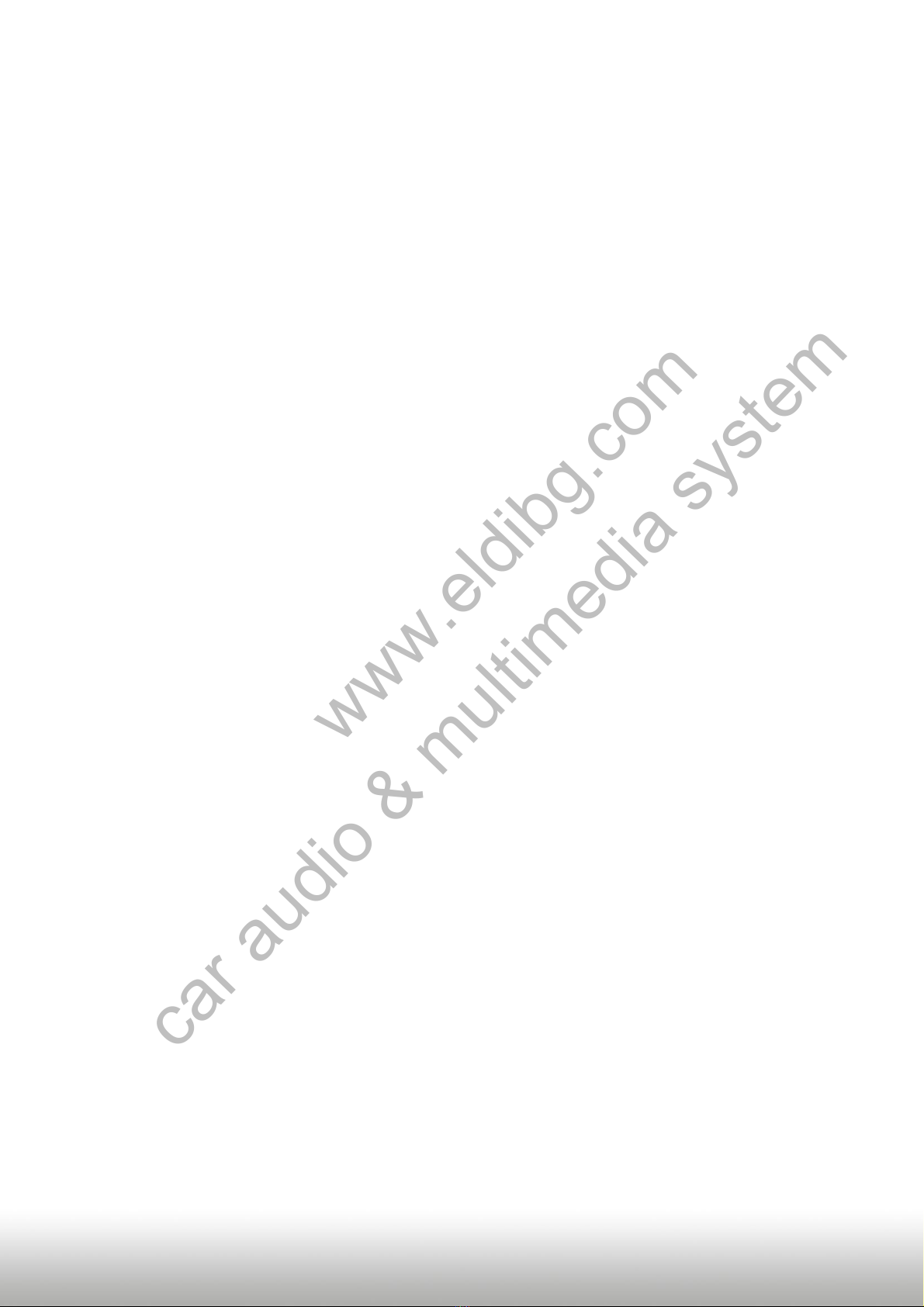
2. Connectionschema
3. Installation
Switchoffignitionand disconnect the vehicle’s battery! Ifaccordingtofactoryrules
disconnectingthebatteryhastobeavoided,itisusuallysufficienttoputthevehiclein
sleep-mode.Incase thesleep-modedoes notshowsuccess,disconnectthebatterywitha
resistorlead.
www.eldibg.com
car audio & multimedia system
Version23.05.2013C1-C20
Page5
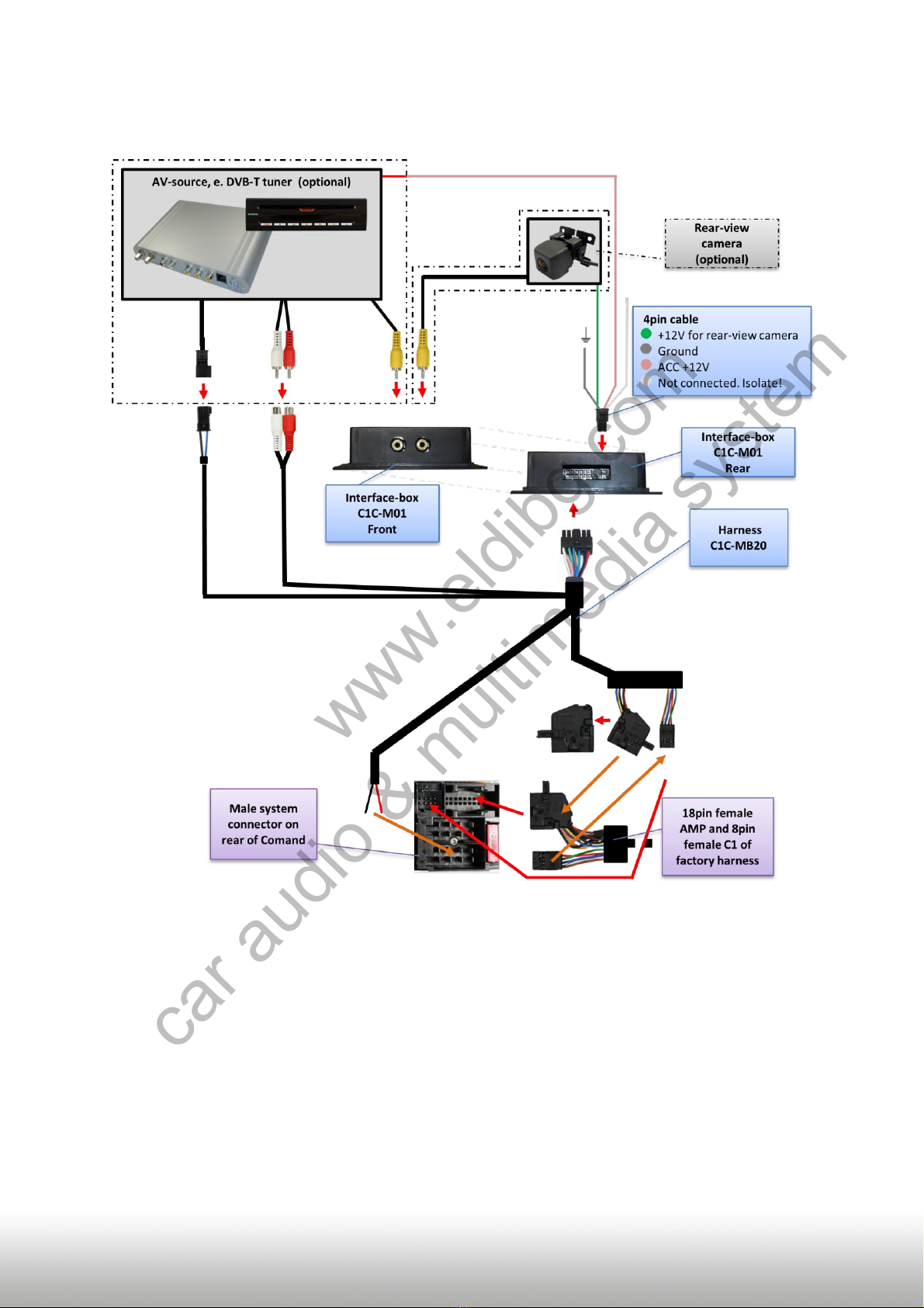
3.1. Connectionsto theComand
Place ofinstallationisbehindtheComand.Removethehead-unitfromthedash-board.
Removeshellfromfemale18pinAMPconnectorofC1C-MB20.
Transferpins2(red),11(white),3and 12(black)from female18pinAMPconnector
ofC1C-MB20tocorrespondingslotsoffemale18pinAMPconnectoroffactory
harness.Ifoccupiedremoveandisolatefactorywires(takenotesbeforeremoving).
Transferpins1and1fromfemale18pinAMPconnectorofC1C-
MB20 tocorrespondingslotsoffemale18pinAMPconnectoroffactoryharness.If
occupiedconnectadditionallytothefactorywires.
Ifexistingtransferpins5and 6fromfemale8pinC1connectoroffactoryharnessto
correspondingslotsoffemale8pinC1connectorofC1C-MB20.Ifexisting,otherpins
remaininthefactoryconnector.
ConnectlooseredwireofC1C-MB20topin4
ofchamberA(+12Vbatterypower).
ConnectlooseblackwireofC1C-MB20topin8
ofchamberA(ground).
Plugfemale18pinAMPconnectorofvehicle
harnessintoC2 slot of Comand’s male
system connector.
Plugfemale8pinC1connectorofharness
C1C-MB20 into C1 slot of Comand’s male
system connector.
C1
C2
A
B
8
4
www.eldibg.com
car audio & multimedia system

Version23.05.2013C1-C20
Page6
3.2. InterconnectingInterface-boxand harnesses
PlugharnessC1C-MB20 into12pinMolexofInterface-boxC1C-M01.
3.3. Connectingperipheral devices
Itispossibletoconnectoneafter-marketAV-sourceandanafter-marketrear-viewcamera
tothe c.LOGiCInterface.
Beforefinal installationoftheperipheral devices,werecommend totest-run thec.LOGiC
functionstodetectincompatibilityofvehicle,navigation,factoryaccessoriesorperipheral
devices assoonaspossible.
www.eldibg.com
car audio & multimedia system

Version23.05.2013C1-C20
Page7
3.3.1.AV-source
Thec.LOGiCinterface hasthepossibilitytoconnectandremotelycontrolbynavigation
buttonsonepre-programmeddevice.Thedevicelistinthedevicecontroltable(AppendixA)
showsthepre-programmedremotechannelsandtherelatedIR-remotecablesSTA-xxx
whichmustbeorderedseparatelyforthecontrolofthedevice.
UsingtherespectiveSTA-xxx IR-controlcable,interconnectthebluefemale3pinAMP
connectorofharnessC1C-MB20 andtheIR-portoftheAV-source.
UsinganRCA-cable,interconnectthefemaleRCA-portVideoInoftheInterface-box
C1C-M01withtheAV-outputoftheAV-source.
ThepinkACC-outputwire(+12Vmax.1A)ofthe4pincablecanbeconnectedtothe
ACC-inputwiresoftheconnecteddevicetoswitchiton.Itcarries+12V whenthe
head-unitisrunning.
3.3.2.InstallingAV-source’s IR-sensoradditionally
AdditionallytothecontrolviaOEMnavigation,itispossibletoinstalltheoriginalIR-sensor
ofaconnecteddevice.ByusingtherespectiveY-adapter(e.g.STA-Y35MM orSTA-RJ12)for
theIR-Portoftheconnecteddevice,the controls of navigation AND device’s IR-sensorcanbe
connectedandusedsimultaneously.InstallationoftheIR-sensorisrecommendedasthe
controlsvianavigationarelimited,and notallfunctionsmaybecovered.
www.eldibg.com
car audio & multimedia system

Version23.05.2013C1-C20
Page8
3.3.3.After-marketrear-viewcamera
ConnectthevideoRCAoftheafter-marketrear-viewcameratofemale
RCAconnectorR-CAMINofInterface-boxC1C-M01.
Connectthegreenwireofthe4pincabletothecamerapowersupply(+12Vmax.1A)
oftheafter-marketrear-viewcamera andthegreywiretogroundofthevehicle.The
greenwireishigh(+12Vmax.1A) whenreversegearisengaged.Thewhitewireis
notconnectedandhastobeisolated.Insome casesitispossiblethattheautomatic
switchingdoesnotwork.Inthiscaseconnectthewhitewiretothereversegearlight
(+12V).
Note:Automaticswitchingtocameraonlyworksfromc.LOGiCmode.
4. Operation
4.1. Activationofthevideo-in-motionfunction
Thevideoofthec.LOGiCisdisplayedalsoinmotion.
Note:OnvehicleswithpreviouslyinstalledfactoryTV-tuneranextravideo-in-motion
interface mightbenecessary.Itisnotpossibletodeterminethispriortotesting.
4.2. Selectingthec.LOGiC ascurrentAV-source
PushTV buttonofComandtochoosethec.LOGiCascurrentAV-source.
www.eldibg.com
car audio & multimedia system

Version23.05.2013C1-C20
Page9
4.3. Assigningdevice control
Afterselectingthec.LOGiCascurrentAVsource,longpress
thenumber“1”-button or shortpress the “RET”-button.
Thedisplayintheinstrumentswillshow“TV 1” and
“RC01”. Turn right knob untilthedevice-relatedIR-codeas
describedindevicecontroltable(appendixA)isreached.
Pushrightknobtoconfirmtheassignment.
IfthevehiclehasnoMFDdisplayintheinstrumentpanel,youmustcountthenotcheswhen
turningtheknob(totheright+1,totheleft -1).Atthesametime,rememberthatthe
startingpointischannelRC01(thefirstnotchtotherightisthenalreadyRC02).
Note: TheIR-controlchannelispresettoRC-Code41compatibleDVB-Ttuners.
4.4. Buttonassignmenttable
Thebuttonassignment tableshowswhichfunctionsoftheconnecteddevicescanbe
executedbyComandbuttons.OncetheAV-inputisactivated,theComandbuttonintheleft
columnwillexecutethefunctiondescribedinthecorrespondingdevicecolumn.The
functiondescriptionequalstheremotecontrolbuttonsoftheoptionalc.LOGiCremote
controlortheadditionaldevice.Ontheadditionaldevicethewritingmayvary(e.g.AV
insteadofSource).
www.eldibg.com
car audio & multimedia system

Version23.05.2013C1-C20
Page10
Additionallytothehead-unitbuttons,thesteering-wheelbuttonsUPandDOWN canbe
usedforremotefunctions.DOWN-buttonhasthesamefunctionas17onthehead-unitand
UP-buttonhasthesamefunctionas18onthehead-unit.
4.5. Picturesettings
Bypressingthebutton10,itispossibletoswitch
between4:3and 16:9pictureformat
(OnlypossibleonComandAPSCD/220).
To enterthepicturesettings menulongpressbutton13.
Thepicture settings menu alwaysstartswiththe
brightnesssettings.Therespectivecurrentpicture
valueisdisplayedontheinstrument panel.
Presstherightknobtochangefrombrightnessto
colourand contrast(aftercontrast,theinterface
startsagainwithbrightness).
Turntherightknobtochangethecurrentpicture
value.To quitthe settings menupressbutton13.
Buttonassignmenttablec.LOGiC Comand 2.0/APS CD/APS220
COMAND
button
DVB-T
USB-LiNK
DVD-player
DVD-
changer
iPod®-control
Analog-tuner
1
SCAN
POWER
PLAY
PLAY
PLAY/PAUSE
SCAN
2
↑
↑
↑
↑
↑
VOL+
3
EPG
EXIT
STOP
STOP
POWER
FM
4
←
←
←
←
←
CH -
4long
DISPLAY
VOL-
DISPLAY
DISPLAY
DISPLAY
5
OK
OK/ PLAY
OK
OK
ENTER
MODE
6
→
→
→
→
→
CH +
6long
AUDIO
VOL+
AUDIO
AUDIO
MUTE
FM
7
EXIT
MEDIA
PBC
DISC
SHUFFLE
MUTE
7long
LANG
OSD
SUB
SUB
MUTE
8
↓
↓
↓
↓
↓
VOL-
9
MENU
SETUP
SETUP
SETUP
LIGHT
ADJUST
11
AV
MEDIA
AV
AV
EJECT
DISPLAY
11 long
POWER
POWER
POWER
POWER
POWER
POWER
14
↓
↓
TRACK+
TRACK+
TRACK+
CH +
15
↑
↑
TRACK-
TRACK-
TRACK-
CH -
16
OK
OK/ PLAY
OK
OK
ENTER
MODE
17
CH -
TRACK-
TRACK-
TRACK-
TRACK-
CH -
18
CH +
TRACK+
TRACK+
TRACK+
TRACK+
CH +
www.eldibg.com
car audio & multimedia system
Version23.05.2013C1-C20
Page11
4.6. Audiosettings
To enter the Comand’s audio settings menu press button 12.
5. Specifications
Operationvoltage10.5–14.8V DC
Stand-bypowerdrain<1mA
Operationpowerdrain240mA
Powerconsumption3W
Temperaturerange-30°Cto+80°C
Weight95g
Measurements(boxonly)BxHxT106 x30x71mm
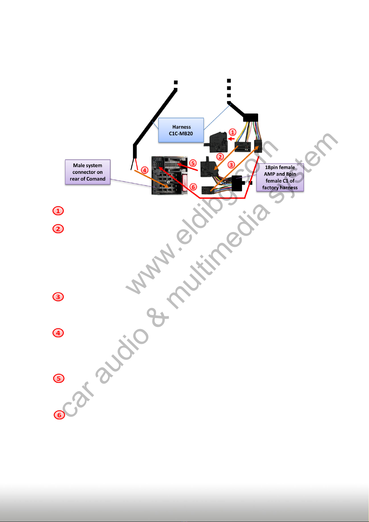
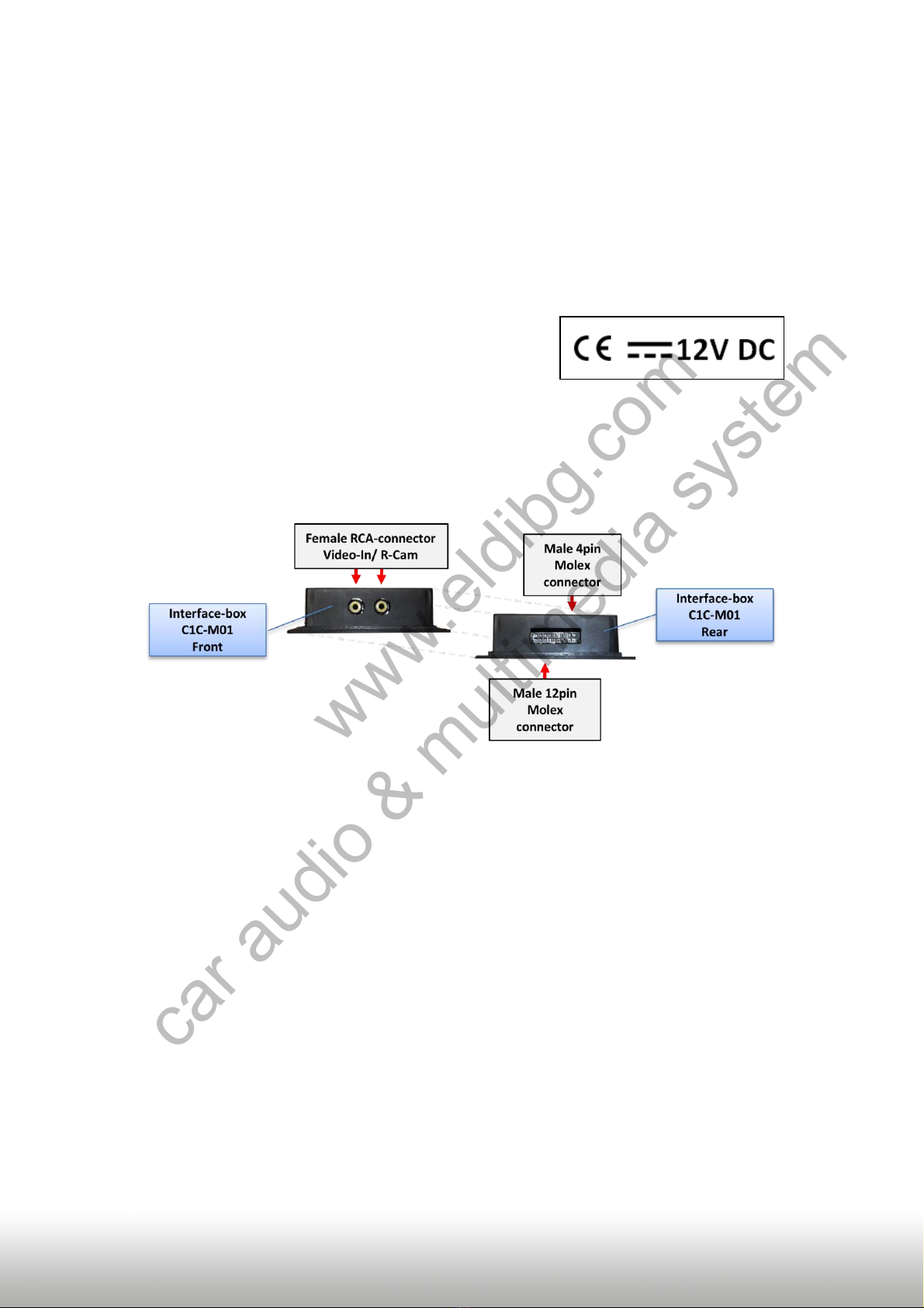
6. Connections(Interface-box)
www.eldibg.com
car audio & multimedia system
Table of contents
Popular Automobile Accessories manuals by other brands


Metra Electronics
Metra Electronics 99-8244HG installation instructions

Bosch
Bosch IMSA Prototype Classes Scrutineering System manual

Uebler
Uebler F14 Mounting and operating instructions

Car-Interface
Car-Interface r.LiNK CI-RL2-RLINK manual

Paser
Paser PARKVIEW CF0006UNPS41 installation manual

Dometic
Dometic FRESHJET FJ2000 operating manual