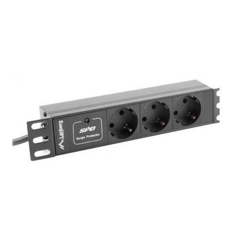
Elecdan ELECPS-8XS-EU User manual

April 2008
ELECPS
ELECPS-
-8XS
8XS-
-EU
EU
Before operating your 8XS, please read the
safety instructions in the User Guide on the
provided CD-ROM.
Detailed information can be found in the
User Guide on the provided CD-ROM
Quick Start Guide
To read out the status of power outlets from your computer, enter the command
as explained below:
Syntax of the command: Rxy <ENTER>
Parameter Value Function
X 1 to 16 means the address of the Satellite (see table §1)
Y 1 to 8 indicates the number of the power outlet you want to control
The 8XS then sends the status of the specified power outlet using following syntax:
Pxy=z<CR><LF>
z = 0 if the power outlet is off
z = 1 if the power outlet is on
<CR> = Carriage Return
<LF> = Line Feed
Examples:
Read out the status of the power outlet 5 of the Satellite with address 1:
R15 <ENTER>
Read out the status of the power outlet 6 of the Satellite with address 2:
R26 <ENTER>
Remark: The 8XS accepts lower case and upper case commands.
L’ELECPS-8XS-EU Satellite is a power distribution and control unit that enables
power management of 8 devices through an RS-232 or RS-485 serial connection.
The number of controlled power outlets can be extended up to 128 by cascading
up to 16 Satellite models.
This 8XS is ideal to control power outlets through the serial connection of a PC, a
KVM switch or a console server. It can also be connected to an 8XM Master to
extend the number of controlled power outlets over IP.
ELECDAN • 2 impasse de la noisette • 91370 VERRIERES-LE-BUISSON • FRANCE
Tél. +33 (0) 1 60 11 44 44 • Fax +33 (0) 1 69 20 39 63 • www.elecdan.com • sales@elecdan.com

ELECPS
ELECPS-
-8XS
8XS-
-EU
EU
1. If the Satellite unit is used with a Master unit, connect the
supplied RJ45 link-up cable to one of the xBus connector of
the 8XM and to one of the xBus connector of
the ELECPS-8XS-EU.
To cascade several Satellites, link the second xBus connec-
tor of a Satellite with the xBus connector of the next Satellite.
2 3 4
DC
DRYCONTACTS
MAX24VDC- 20mA 12VDCAUX
POWERSUPPLY
I/O
A 1 2 3 4 10/100
Link 100
RS232 xBus Term S B 5 6 7 8 1
RS232Slct
Term
86 7
xBus
3 4 5
Power
2B 1A
RS232Slct
Term
86 7
xBus
3 4 5
Power
2B 1A
2. Allocate an address to each Satellite by positioning the
address selection DIP-switches marked "Slct" on the front
panel according to the following table.
- Unplug the power cords of the ELECPS-8XS-EU before
changing its DIP switches.
- Do NOT use the same address for two different Satellites.
Position Off = switch upwards,
Position On = switch downwards
DIP-Switch 1 is located on the left
side
DIP-Switch 5 and 6 are used to
activate the built in termination
resistors.
[ON][ON][ON][ON]1
[ON][ON][ON]Off15
[ON][ON]Off[ON]14
[ON][ON]OffOff13
[ON]Off[ON][ON]12
[ON]Off[ON]Off11
[ON]OffOff[ON]10
[ON]OffOffOff9
Off[ON][ON][ON]8
Off[ON][ON]Off7
Off[ON]Off[ON]
Off[ON]OffOff5
OffOff[ON][ON]4
OffOff[ON]Off3
OffOffOff[ON]2
OffOffOffOff1
DIP-Switch
4
DIP-Switch
3
DIP-Switch
2
DIP-Switch
1
Satellite
Adress
3. On both devices located at the end of the xBus, switch
the DIP-Switch 5 and 6 to ON to activate the termination
resistors.
4. Plug the 2 power cables into 2 grounded sockets. The A and B
LEDs light on to confirm that power is on.
2. Controlling the power outlets using a
Terminal connection
The power outlets of the ELECPS-8XS-EU can be individually controlled and the
status of each power outlet can be read out using a simple ASCII protocol through a
serial connection.
The connection can be done:
- using the RS232 port (SubD-9F connector marked RS232 on the front panel).
In this case, use the supplied serial cable to connect the EPS to
an available serial port of your PC.
- using the RS485 port (RJ45 connector marked xBus on the front panel). In
this case, you have to make a special serial cable (see user guide on the CD).
Run a terminal program such as Windows HyperTerminal or the MicroTerminal
program on the CD (folder miscellaneous) and configure the appropriate serial port
with the following settings: 9.600 bauds, 8 bits, no parity, 1 stop bit and no flow
control.
If you use the MicroTerminal program on the CD you only have to choose the used
serial port, this program is already configured at 9600, n, 8, 1.
To control the power outlets from your computer, enter the command as explained
below:
Syntax of the Command : Pxy=z
Parameter Value Function
x 1 to 16 Means the corresponding connected Satellite address
y 0 Means that all the sockets have to be controlled together
1 to 8 Indicates the number of the socket you want to control
z 0 Command to switch the socket(s) OFF
1 Command to switch the socket(s) ON
r Command to restart the socket(s)
t Command to toggle the state of the socket
Example to control the Satellite with address 1 Example to control the satellite with address 2
=> DIP-Switch: 1, 2, 3 and 4 = Off DIP-Switch: 1 = on, DIP-Switch: 2, 3 and 4 = off
P10=1 <ENTER> switch all 8 sockets ON P20=1 <ENTER> switch all 8 outlets ON
P10=0 <ENTER> switch all 8 sockets OFF P25=0 <ENTER> switch outlet 5 OFF
P14=r <ENTER> restart socket 4
P18=t <ENTER> toggle socket 8
The 8XS accepts lower case and upper case commands.
The 8XS sends the command back as an echo.
1. Installation

Avril 2008
ELECPS
ELECPS-
-8XS
8XS-
-EU
EU
Pour connaître l'état des prises secteurs à partir de votre PC, entrez la commande
selon les indications suivantes :
Avant d’utiliser votre 8XS, lisez attentivement
les consignes de sécurité indiquées dans le
User Guide contenu sur le CD-ROM.
Des informations détaillées se trouvent dans le
User Guide sur le CD-ROM fourni
Guide d'installation rapide
Syntaxe de la commande : Rxy <ENTER>
Paramètre Valeur Fonction
X 1 à 16 indique l'adresse de l’ELECPS-8XS-EU (cf tableau §1)
Y 1 à 8 indique le numéro de la prise
Le 8XS envoie l'état de la prise secteur spécifiée en utilisant la syntaxe suivante :
Pxy=z<CR><LF>
z = 0 si la prise est hors tension (OFF)
z = 1 si la prise est sous tension (ON)
<CR> = Carriage Return
<LF> = Line Feed
Exemples :
Pour connaître l'état de la prise secteur 5 de l‘EPS Satellite 1 :
R15 <ENTER>
Pour connaître l'état de la prise secteur 6 de l‘EPS Satellite 2 :
R26 <ENTER>
Remarque : l‘EPS Switch accepte les commandes en majuscules et minuscules
L’ELECPS-8XS-EU Satellite est un système de contrôle et de distribution
d'alimentation qui permet de commander à distance 8 prises secteur via une
connexion série RS-232 ou RS-485.
Le nombre de prises contrôlées peut être étendu jusqu'à 128 grâce à la connexion
en cascade de 16 ELECPS-8XS-EU Satellite.
La commande des prises secteur peut se faire au travers d’un 8 XM Master, d'un
PC, d'un KVM switch ou d'un serveur de console.
ELECDAN • 2 impasse de la noisette • 91370 VERRIERES-LE-BUISSON • FRANCE
Tél. +33 (0) 1 60 11 44 44 • Fax +33 (0) 1 69 20 39 63 • www.elecdan.com • sales@elecdan.com

ELECPS
ELECPS-
-8XS
8XS-
-EU
EU
1. Connectez le câble de liaison RJ45 fourni à l'un des connec-
teurs xBus du 8XM et à l'un des connecteurs
xBus de l'ELECPS-8XS-EU.
Pour cascader plusieurs Satellites, reliez le deuxième con-
necteur xBus du Satellite à l'un des connecteurs xBus du
Satellite suivant.
2 3 4
DC
DRYCONTACTS
MAX24VDC- 20mA 12VDCAUX
POWERSUPPLY
I/O
A 1 2 3 4 10/100
Link 100
RS232 xBus Term S B 5 6 7 8 1
RS232Slct
Term
86 7
xBus
3 4 5
Power
2B 1A
RS232Slct
Term
86 7
xBus
3 4 5
Power
2B 1A
2. Allouez une adresse à chaque Satellite en positionnant le
DIP-switch (sur la face avant) marqué "Slct" (cf tableau).
- Débranchez les câbles d'alimentation de l'appareil avant de
positionner les DIP switch.
- N'attribuez JAMAIS la même adresse à plusieurs appareils.
Position Off = switch vers le haut
Position On = switch vers le bas
Le DIP-Switch 1 est situé à gauche
Les DIP-Switch 5 et 6 permettent
d'activer les résistances de
terminaison
[ON][ON][ON][ON]1
[ON][ON][ON]Off15
[ON][ON]Off[ON]14
[ON][ON]OffOff13
[ON]Off[ON][ON]12
[ON]Off[ON]Off11
[ON]OffOff[ON]10
[ON]OffOffOff9
Off[ON][ON][ON]8
Off[ON][ON]Off7
Off[ON]Off[ON]
Off[ON]OffOff5
OffOff[ON][ON]4
OffOff[ON]Off3
OffOffOff[ON]2
OffOffOffOff1
DIP-Switch
4
DIP-Switch
3
DIP-Switch
2
DIP-Switch
1
Adresse
8XS-EU
3. Sur les 2 appareils situés à chaque extrémité du réseau xBus,
activez les résistances de terminaison en mettant les DIP-
Switch 5 et 6 sur ON.
4. Reliez les 2 câbles d'alimentation à des prises secteur avec
terre. Les LEDs A et B s'allument lorsque l‘EPS est
sous tension.
Les prises secteurs de l’ELECPS-8XS-EU peuvent être contrôlées individuellement
et leur statut peut être connu en utilisant un simple protocole ASCII via une
connexion série.
La connexion peut être réalisée :
- via le port RS232 (connecteur série DB-9F sur la face avant). Dans ce cas, utilisez
le câble série fourni pour connecter l‘EPS à un port série disponible de
votre PC.
- via le port RS485 (connecteur RJ45 marqué xBus sur la face avant). Dans ce cas
il vous faut réaliser un câble série spécifique (cf brochage dans le manuel fourni
sur le CD-ROM).
Démarrez un programme terminal tel que Windows HyperTerminal ou le programme
MicroTerminal sur le CD fourni (répertoire miscellaneous) et configurez le port série
à 9.600 bauds, 8 bits, n, 1 et sans contrôle de flux.
Si vous utilisez le programme MicroTerminal fourni sur le CD, il vous suffit de
sélectionner le port série utilisé, le programme étant déjà paramétré à 9600, n, 8, 1.
Pour contrôler les prises secteur à partir de votre PC, entrez les commandes
comme expliqué ci-dessous :
Syntaxe de la commande : Pxy=z
Paramètre Valeur Fonction
x 1 à 16 indique l'adresse de l‘EPS Satellite
y 0 indique que toutes les prises doivent être commandées
ensemble 1 à 8 indique la prise secteur à commander
z 0 mettre la prise secteur hors tension (OFF)
1 mettre la prise secteur sous tension (ON)
r redémarrer la prise secteur (restart = OFF puis ON)
t basculer l'état courant de la prise secteur (toggle)
Exemple de commande de l'ELECPS-8XS-EU 1
⇒DIP-Switch: 1, 2, 3 et 4 = Off
P10=1 <ENTER> mettre toutes les 8 prises sous tension (ON)
P10=0 <ENTER> mettre toutes les 8 prises hors tension (OFF)
P14=r <ENTER> redémarrer la prise 4
P18=t <ENTER> basculer l'état de la prise 8
Exemple de commande de l'ELECPS-8XS-EU 2
DIP-Switch: 1 = on, DIP-Switch: 2, 3 et 4 = off
P20=1 <ENTER> mettre toutes les 8 prises sous tension (ON)
P25=0 <ENTER> mettre la prise 5 hors tension (OFF)
1. Installation
2. Contrôle des prises secteurs au travers
d'une connexion terminal RS232
Table of contents
Languages:


