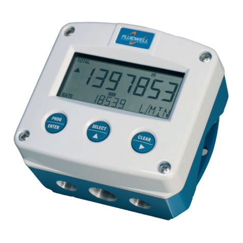
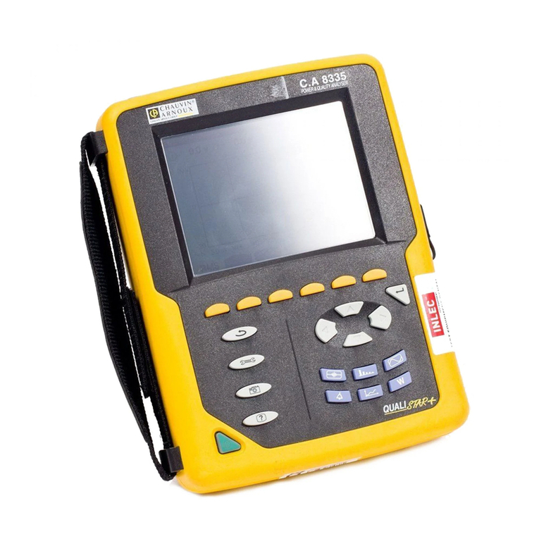
Elecsys WATCHDOG II MESH User manual

81-0006-00 Rev E 01-2020
WATCHDOG II MESH
Wireless Remote Monitoring System
Installation and Operation Manual
GSM Cellular
CDMA Cellular
Inmarsat IDP Satellite
System Part Numbers: WD2-00-1XXX-XX (IDP Satellite w/o Integrated Enclosure)
WD2-00-8XXX-XX (CDMA Cellular w/o Integrated Enclosure)
WD2-00-9XXX-XX (GSM Cellular w/o Integrated Enclosure)
WD2-16-1XXX-XX (IDP Satellite w/16X14 Integrated Enclosure)
WD2-16-8XXX-XX (CDMA Cellular w/16X14 Integrated Enclosure)
WD2-16-9XXX-XX (GSM Cellular w/16X14 Integrated Enclosure)

Watchdog II Mesh User Manual
P/N 86-0006-00 Rev E 01-2020 Page 2 of 38
Contents
Materials Supplied................................................................................................................................. 4
General Introduction.............................................................................................................................. 5
1.1 Wireless Sensor Measurement Modules ................................................................................. 5
1.2 Watchdog II Base Station Wired Sensor Inputs ....................................................................... 5
1.2.1 Dry Contact Digital Inputs................................................................................................. 5
1.2.2 Open Collector Digital Output........................................................................................... 5
1.2.3 Pulse Counter / Accumulator Digital Input ........................................................................ 6
1.2.4 Analog Input (0-5 VDC or 4 –20 mA)............................................................................... 6
1.3 Data Communications............................................................................................................. 6
1.3.1 Digital Cellular.................................................................................................................. 6
1.3.2 Inmarsat Satellite using ISatM2M data protocol................................................................ 7
1.3.3 Modbus based SCADA system using a Modbus data radio.............................................. 7
Base Station Power Options.................................................................................................................. 8
1.4 Continuous (always on) Power Options................................................................................... 8
1.4.1 115 / 230 Volts AC Line Power......................................................................................... 8
1.4.2 Low Voltage AC Power: Rectifier Secondary Taps (12-25 Volts AC recommended)........ 9
1.4.3 Low Voltage DC Power: TEG Power or Large Solar System (10-35 Volts DC)............... 9
Field Installation Instructions.................................................................................................................. 9
1.5 Preparation Prior to Going to Field .......................................................................................... 9
1.5.1 Gather Proper Installation Materials & Tools .................................................................. 10
1.5.2 System Setup (DIP switch settings)................................................................................ 10
1.5.3 Configuring and Linking the Smart Node Channels ........................................................ 12
1.5.4 Link the Interruption Module (if Interruption capability is included)................................. 15
1.6 Field Installation Instructions ................................................................................................. 16
1.6.1 Step 1: Determine the Positive Terminal on the Current Shunt.............................. 16
1.6.2 Step 2: Turn off the rectifier AND shut off the circuit breaker to the rectifier............ 16
1.6.3 Step 3: Connect Power to the Interrupter Module...................................................... 16
1.6.4 Step 4: Mount Satellite Modem (if satellite model was ordered)............................... 16
1.6.5 Step 5: Mount the Base Station.................................................................................... 17
1.6.6 Step 6a: 115/230 VAC Wiring Option............................................................................. 18
1.6.7 Step 6b: Rectifier Secondary Tap Option (Low voltage AC)........................................... 19
1.6.8 Step 6c: Low Voltage DC Power Option (+10 to 35 volts DC)........................................ 19
1.6.9 Step 7: Wire External Inputs.......................................................................................... 19
1.6.10 Step 8: Install the 3-Channel Smart Node (P/N NTG-01- 0002-01).............................. 20
1.6.11 Step 9: Install the “AC Probe” Rectifier Input Power Sensor.......................................... 22
1.6.12 Step 10: Install the Interrupter Relay System............................................................... 22
1.6.13 Step 11: Install the GPS Antenna.................................................................................. 23
1.6.14 Step 12: Install the Interrupter II Mesh Module (NTG-01-0006- XX)............................ 23
1.6.15 Step 13: Perform a PUSHBUTTON TEST to verify proper operation............................. 24
Using the Pipeline Watchdog Web Monitor.......................................................................................... 25
1.7 Log onto the Elecsys WatchdogCP Web Monitor .................................................................. 25
1.8 Enter Site Data...................................................................................................................... 25
1.9 Enter Data Labels and Descriptions ...................................................................................... 26
1.10 Setting Important Operational Parameters......................................................................... 26
1.10.1 Wakeup/Sampling Interval.............................................................................................. 27

Watchdog II Mesh User Manual
P/N 86-0006-00 Rev E 01-2020 Page 3 of 38
1.10.2 Reporting Schedule........................................................................................................ 28
1.11 Alarm Notification Setup..................................................................................................... 28
1.11.1 Types of Alarm Notifications........................................................................................... 29
1.11.2 Getting E-mail Notifications ............................................................................................ 29
1.11.3 Getting Cell Phone SMS Text Messages........................................................................ 30
WatchdogCP Remote Monitoring System Component Specifications.................................................. 31
1.12 Base Station (powered) (NTG-01-1111-00 / 01)................................................................. 31
1.13 Smart Node Voltage Measurement Range......................................................................... 31
1.14 Smart Node Current Measurement Range......................................................................... 31
1.15 Smart Node Pipe-to-Soil Measurement Range................................................................... 31
1.16 Base Station Analog Input.................................................................................................. 32
1.16.1 4-20mA Input.................................................................................................................. 32
1.16.2 0-5V Input....................................................................................................................... 32
1.17 Base Station Digital Output................................................................................................ 32
1.18 Base Station Discrete Inputs.............................................................................................. 32
1.19 Base Station Accumulator.................................................................................................. 32
Technical Support................................................................................................................................ 33
1.20 Products Under Warranty................................................................................................... 33
1.21 Products Not Under Warranty............................................................................................ 33
1.22 Elecsys Address and Contact Information.......................................................................... 34
Warranty Policy ................................................................................................................................... 35
Appendix A –Miscellaneous Website Commands............................................................................... 36

Watchdog II Mesh User Manual
P/N 86-0006-00 Rev E 01-2020 Page 4 of 38
Materials Supplied
After unpacking the units and checking for obvious damage, make sure the following items have been
supplied with each WatchdogCP Wireless Remote Monitoring System ordered:
For cellular communication based WatchdogCP RMU Systems:
1 ea. WatchdogCP ‘Mesh’ RMU (P/N NTG-01-0003-00)
2 ea. RMU mounting brackets
1 ea. 3-Channel “Smart Node” Analog Measurement Module (P/N NTG-01-0002-00)
1 ea. AC Probe –AC current sensor to determine presence of AC power at the Rectifier
4 ea. NiMH Rechargeable Batteries for the Smart Node
For satellite communication based WatchdogCP RMU Systems:
1 ea. WatchdogCP ‘Mesh’ RMU (P/N NTG-01-0003-01)
2 ea. RMU mounting brackets
1 ea. Skywave IDP satellite modem with right-angle mounting bracket
1 ea. 3-Channel “Smart Node” Analog Measurement Module (P/N NTG-01-0002-00)
1 ea. AC Probe –AC current sensor to determine presence of AC power at the Rectifier
4 ea. NiMH Rechargeable Batteries for the Smart Node
If permanent Interruption capability has been ordered, the following additional items are supplied:
1 ea. Interrupter II Module (P/N NTG-01-0006-XX)
Relay Options (-XX):
100 Amp Mercury Relay
100 Amp Solid State AC Relay with 100 Amp Mercury Bypass Relay
100 Amp Solid State DC Relay with 100 Amp Mercury Bypass Relay
1 ea. Trimble GPS antenna (P/N 42-0018-00)
1 ea. Interruption system wire harness cable
1 ea. Current sensor for the interrupter system

Watchdog II Mesh User Manual
P/N 86-0006-00 Rev E 01-2020 Page 5 of 38
General Introduction
The Pipeline WatchdogCP ‘Mesh’ RMU is designed to measure, monitor, and report the output of
cathodic protection rectifiers and other sensor and transducer devices. Monitored data is:
Compared to programmable alarm limits for exception alarm reporting
Transmitted to the Elecsys Pipeline Watchdog Web Monitor database for viewing and reporting
Elecsys’ Pipeline Watchdog Website allows the user to:
Set up e-mail and text message alarms
Set up regular emailed CP rectifier and test station data reports
Obtain on-demand data reports
Change alarm limit parameters, reporting frequency and monitoring frequency over the air
1.1 Wireless Sensor Measurement Modules
The Watchdog II system uses wireless, battery-powered 3-channel sensor modules (Smart Nodes) that
are easily installed to measure voltage, current, and potential. The sensor modules are periodically
‘pinged’ by the Base Station to request data measurements.
The Watchdog II Base Station can monitor up to sixteen (16) channels (5 Smart Nodes), each of which
can be located up to 150 feet (45 meters) from the Base Station with an unobstructed line-of-sight. The
sensors can typically be read from the Base Station at a range of 50 feet through a rectifier housing or
building walls.
These wireless sensors represent a major development in the field of CP rectifier monitoring, where
lightning damage has long been a nemesis. Elecsys’ wireless sensors are electrically isolated from
rectifier power or ground, and are simply connected across the rectifier output or across the rectifier
shunt in the same manner that one would connect a hand held voltmeter. They are protected against
high voltage transients and do not provide a low impedance path to ground for lightning current.
Each Smart Node is powered by a 4 NiMH rechargeable batteries that should last in excess of 3 years
under normal operating conditions. Replacement batteries are available from Elecsys as well as many
battery specialty companies (Batteries Plus, etc.). The batteries are easily replaced in the field.
1.2 Watchdog II Base Station Wired Sensor Inputs
1.2.1 Dry Contact Digital Inputs
The Watchdog II Base Station has the ability to monitor up to four dry contact digital inputs (Pins 1 –4,
with pin 9 as a common). The open/closed contact to be monitored should be wired to any one of the
four inputs and the Base Station common reference (pin 9).
1.2.2 Open Collector Digital Output
The Watchdog Base Station also has a digital output (J2, pins 5 and 9) that can be used to turn on and
off various devices. Pin 5 can sink up to 115 mA. The digital output can be linked to any or all of the

Watchdog II Mesh User Manual
P/N 86-0006-00 Rev E 01-2020 Page 6 of 38
discrete inputs or the digital output can also be controlled independently. The setup of the digital output
is done through the website.
1.2.3 Pulse Counter / Accumulator Digital Input
Another dry contact input (Pins 6 and 9) on the Base Station can be used as a pulse counting
accumulator. A typical application would be to read an electric meter or a transfer station volume
counter. If the accumulator is used, it will occupy one of the 16 measurement channels that the Base
Station can monitor.
1.2.4 Analog Input (0-5 VDC or 4 –20 mA)
An analog signal can also be monitored by the Base Station. Its analog input (J2, pins 7, 8, and 9) can
be set up to monitor a 4-20 mA two terminal device, a 4-20 mA three terminal device, or a 0-5V device.
The device is continuously monitored by the Base Station. Alarms conditions will be reported whenever
the analog input is outside of user defined alarm limits for a user defined amount of time. If the analog
signal input is used, it will occupy one of the 16 measurement channels that the Base Station can
monitor.
The Base Station can also monitor the DC power input. This is useful if the base station is powered by
a solar panel. The base station could monitor the actual voltage being supplied by the solar panel and
report that voltage to the website. If the DC power input is to be monitored, it will occupy one of the 16
measurement channels.
1.3 Data Communications
The function of the Base Station is to wirelessly collect voltage readings from the wireless modules and
local analog and digital inputs, determine if an alarm condition or periodic report condition exists, and
transmit the readings in short data packets to the Pipeline Watchdog website. Data can be transmitted
and received via an internal GSM digital cellular radio or an external Skywave Inmarsat satellite modem
terminal.
The Base Station implements two-way handshaking communications so that its transmissions are
positively acknowledged by the website, and vice versa. In the event the initiating end (the Base
Station or the website) does not receive an acknowledgement (ACK) from the receiving end, it will
attempt a retry after several minutes. If an ACK is still not received, a third and final retry will be
initiated several minutes later. This 3X redundant data packet transmit/ACK protocol makes the
WatchdogCP RMU system extremely robust from a communications standpoint.
The following communications options are available for the Watchdog II Base Station:
1.3.1 Digital Cellular
Digital cellular coverage is widespread throughout the world in urban and suburban areas and along
most highways. Its coverage footprint continues to grow. The major CDMA carrier in the US is
Verizon, GSM carriers in North America are AT&T and T-Mobile (plus Rogers in Canada and Telcel in
Mexico). Elecsys’ GSM RMUs will work wherever GSM coverage exists in North America.

Watchdog II Mesh User Manual
P/N 86-0006-00 Rev E 01-2020 Page 7 of 38
Elecsys’ units will work on GSM networks throughout most Europe, South America, Asia, and the
Middle East, though it depends on the roaming agreements that the local GSM carriers have with AT&T
and O2/Telefonica. Contact Elecsys for specific guidance regarding GSM operations in areas outside
of North America.
1.3.2 Inmarsat Satellite using ISatM2M data protocol
For extremely remote areas, or anywhere in the world, Elecsys offers a cost-effective satellite option:
Inmarsat IDP service. Inmarsat is the major satellite operator for international maritime and aviation
communications, and its satellite network offers global coverage using geostationary satellites, spaced
around the world over the equator. Inmarsat IDP is a two-way, short data packet service that is ideally
suited for remote monitoring applications.
The satellite equipped Base Station uses a small (6 in. [15 cm] diameter), low power Skywave satellite
modem to transmit data to and receive commands and configurations from the WatchdogCP website.
It must be pointed to the nearest satellite just like a satellite TV dish.
1.3.3 Modbus based SCADA system using a Modbus data radio
The Watchdog II RMU can also be configured to work as a Modbus slave RTU. The RMU is interfaced
to a user-supplied data radio using its RS-232 radio modem interface. Once properly configured, the
user is able to read and write to Modbus register and coil locations to acquire up to 16 channel values,
change the alarm settings, etc.

Watchdog II Mesh User Manual
P/N 86-0006-00 Rev E 01-2020 Page 8 of 38
Base Station Power Options
The Watchdog II Base Station has three (3) power options:
1. External 115/230 VAC (using AC mains and a separate 5A mains circuit breaker)
2. External 8-30 VAC (using an isolated step-down AC transformer, or a low voltage AC tap
off of the secondary side of the rectifier transformer)
3. External 10-40 VDC (using a DC power source that can continuously supply 250 mA,
such as a large solar panel system or thermoelectric generator (TEG))
Each option has its advantages and disadvantages. The best power option will depend upon the
nature of the remote site (difficulty of access, availability of external power, etc.) and the preference of
the user.
1.4 Continuous (always on) Power Options
If real time polling and interruption are desired, the Base Station must have a reliable, continuous
power source. In the event of external power failure, the unit will continue to operate for two weeks
using its internal backup battery, in a power conservation mode. It will transmit a Power Fail message
to the website and will continue to do so every 3 days until its battery is depleted or until power is
restored, at which point it will transmit a Return to Normal message
The RMU can be wired to obtain power from any of the following sources:
1.4.1 115 / 230 Volts AC Line Power
The unit can be powered by a single phase 115 or 230 V, 50 or 60 Hz AC circuit.
It is recommended that a separate 5 Amp circuit breaker be installed in the breaker box that supplies
the rectifier. This allows the power to the RMU to be switched on or off, independent of the rectifier
power. The Interrupter II option may be powered from the same source.
NOTE: Do not use a circuit breaker with a rating greater than 5 Amps.
A ¾” flexible conduit should be run from the electrical junction box to the Base Station, and the circuit
should be connected with two 14 AWG electrical power wires (line and neutral).
The Base Station case is non-conductive plastic. DO NOT run a ground wire from the junction box to
the Base Station.
Advantages:
Continuous power allows real-time polling, interruption control, and reconfiguration
A separate circuit breaker for power, with no electrical connection to the rectifier, increases
lightning protection
Allows more frequent data transmissions

Watchdog II Mesh User Manual
P/N 86-0006-00 Rev E 01-2020 Page 9 of 38
1.4.2 Low Voltage AC Power: Rectifier Secondary Taps (12-25 Volts
AC recommended)
The unit can also be powered by tapping off the secondary windings of the rectifier transformer. An AC
voltage of 8 to 30 volts can be found and used to power the Base Station, but 12 to 25 volts is
recommended as the interrupter can be powered from the same source.
Advantages:
Continuous power allows real-time polling, interruption control, and reconfiguration
Allows more frequent data transmissions
Disadvantages:
Wiring into rectifier secondary slightly increases lightning susceptibility
1.4.3 Low Voltage DC Power: TEG Power or Large Solar System
(10-35 Volts DC)
The base station and interrupter can also be powered with a DC source of +10 to +35 volts DC power
@ < 250 mA
Advantages:
Good lightning protection
Good for remote sites with no electric power available
Continuous power allows real-time polling, interruption control, and reconfiguration
Allows more frequent data transmissions
Typical continuous current draw at +12 VDC: 110 mA (cellular system); 200 mA (Satellite
system)
Field Installation Instructions
The WatchdogCP ‘Mesh” RMU System is simple to install in the field. The effort required will depend
on how the Base Station will be powered and whether the GPS-synchronized interruption components
are being installed.
NOTE: This equipment shall not be operated in a manner that has not been specified by
Elecsys. Failure to comply could result in impairment of safety standards used to certify this
equipment.
1.5 Preparation Prior to Going to Field
To simplify the field installation (and avoid multiple trips to the hardware store), Elecsys recommends
that the installer prepare the unit and gather the installation materials prior to heading to the field.
In general, the installer will need to provide the sundry fastening hardware and crimp terminals that will
be needed to mount the RMU enclosure, satellite antenna bracket, ‘mesh’ nodes, and interrupter switch

Watchdog II Mesh User Manual
P/N 86-0006-00 Rev E 01-2020 Page 10 of 38
at the rectifier site. The specific items required will depend on the type of rectifier, the site specifics,
and the preferences of the user.
1.5.1 Gather Proper Installation Materials & Tools
Tools required: Battery powered drill / screwdriver
Wire cutters
Heavy duty cable cutters
Wire stripper
Utility knife
Crimping tool
Heavy duty compression crimper
Fluke voltmeter
Greenlee punch
Additional Installation Material needed:
4 ea. ¼” X 2½” lag screws to mount RMU and antenna bracket (McMaster Carr #94048A224
wood screws for utility pole mount, or #90064A633 self-tapping metal screws for mounting to
metallic structures)
1/4"ID x 3/4" OD fender washer (McMaster-Carr 98026A029)
Approximately 5 feet (10 feet if incorporating interruption) 1” non-metallic flexible conduit
(McMaster-Carr 7581K44)
1 ea. (2 ea. If incorporating interruption) 1” non-metallic conduit fitting (McMaster-Carr 7119K74)
10 ea. #22-18 insulated spade terminals for #10 stud (McMaster-Carr 69145K914)
10 ea. #18-22AWG 3/8" Ring Terminals (McMaster-Carr 7113K834)
10 ea. #18-22 AWG In-Line Splice (McMaster-Carr 7227K12)
Approximately 12 ea. 8" to 11” Wire ties
For Interrupter Installation:
5 to 6 feet #4 Flexible Welding Cable (McMaster-Carr 7940A22)
2 ea. #4 crimp ring terminals for 3/8” stud (McMaster-Carr 7113K232)
2 ea. #22-18 ring terminals for 3/8” stud (for use if interrupting at the AC secondary) (McMaster-
Carr 7113K834)
#2-#6 AWG Copper Bolt Splice (for use if interrupting at the DC output) (McMaster-Carr
6921K61)
The accessories listed above are available in the optional “Watchdog Installation Accessories
Kit” part number WD-48-0002-00
1.5.2 System Setup (DIP switch settings)
NOTE: If DIP switch settings 2 and 3 are to be changed from their current position, do so when
power is off and battery is unplugged.
NOTE: If DIP switch settings 1, 4, 5, 6, or 7 are to be changed from the current position, do so
before linking mesh modules in step 4.1.3. Otherwise linked mesh modules could be overridden
by the DIP switch measurement channels. If no mesh modules are being used, link mode must
still be entered to enable the DIP switch measurement channels (see section 4.1.3).

Watchdog II Mesh User Manual
P/N 86-0006-00 Rev E 01-2020 Page 11 of 38
The base station can be configured to meet specific remote monitoring requirements. This is done by
determining which options are required and setting them accordingly on the dip switch on board (see
figure below).
A. Off Potential Reading
a. If a Pipe to Soil channel and an interrupter module are both installed, this DIP switch
setting can be used enable an OFF potential measurement.
b. First, the Pipe to Soil channel will take a normal reading. The base station will then
command the interrupter to turn the current off. The Pipe to Soil channel will then take
an off potential reading. Both readings will be transmitted to the website.
c. To activate this option, set switch #1 to the On position
d. If the off potential reading is not desired, leave the switch in the default OFF position.
B. ‘Always On’ Powered or ‘Trickle Charge’ Powered
a. For a continuous ‘always on’ powered unit leave switch #2 in the default OFF position.
b. For a trickle charge unit using the small solar panel option, set switch #2 to ON.
C. Cellular Frequency Setting
a. If the system is being used in North America, keep switch #3 in the default OFF position.
b. If the system is being used in Europe or the mid-east, set switch #3 to ON
D. Analog Measurement Channel
a. To activate the on board analog measurement channel, set switch #4 to the ON position.
b. To keep the analog input deactivated, keep switch #4 in the default OFF position.
E. 4-20mA or 0-5V Measurement Type
a. If the analog measurement channel has been activated using switch #4, switch #5 will
determine which type of measurement will be used. If a 4-20mA signal is being used,
leave switch #5 in the default OFF position.
b. For a 0-5V input signal, set switch #5 to the ON position.
System Setup DIP Switch
1 = Off Potential Enable (ON=enabled)
2 = Always ON or Trickle Charged (ON=Trickle Charged)
3 = Cellular –North Amer. Or Europe (ON=Europe)
4 = Analog Measurement Enable (ON=enabled)
5 = Analog Measurement Type (ON=0-5V)
6 = Accumulator Enable (ON=enabled)
7 = Solar Panel Voltage Monitor Enable (ON=enabled)

Watchdog II Mesh User Manual
P/N 86-0006-00 Rev E 01-2020 Page 12 of 38
F. Accumulator Channel
a. To enable the accumulator input, set switch #6 to the ON position
b. To keep the accumulator deactivated, keep switch #6 in the default OFF position.
G. Solar Channel
a. To monitor the incoming DC voltage from a Solar Panel or a TEG, set switch #7 to the
ON position.
b. If monitoring the incoming DC voltage is not desired, keep switch #7 in the default OFF
position
1.5.3 Configuring and Linking the Smart Node Channels
Configuring the Smart Node Channels
If the Smart Node was ordered as a complete RMU system from Elecsys, the Smart Node channels
should be configured to the end users application.
If the Smart Node was not configured before it left the factory, the default channel configuration is
Channel 1 = Voltage (+/- 100V), Channel 2 = Current (+/- 100mV), and Channel 3 = Pipe to Soil (+/-
10V). To change the configuration of the Smart Node channels follow steps 1 –6 below:
1. Hold down the Setup Button until the CH 1 LED turns on. The LED will turn on after
approximately 3 seconds. When the LED turns on, release the button.
2. All the LEDs will begin to cycle on and off indicating the Smart node is waiting for the
channel selection. Push the appropriate channel button for the channel you wish to
configure. To exit without changing any of the channels configurations, press and hold the
Setup Button for approximately 5 seconds.
3. Once a channel has been selected, the corresponding channel LED will begin to flash every
3 seconds. The number of flashes that occurs indicates the current channel configuration.
1 flash = Voltage Channel (+/-100V)
2 flashes = Current Channel (+/- 100mV)
3 flashes = Potential Channel (+/- 10V)

Watchdog II Mesh User Manual
P/N 86-0006-00 Rev E 01-2020 Page 13 of 38
4 flashes = Current Channel using capacitor charge (+/- 100mV)
4. To change the channel configuration push the appropriate CH Button. Before pushing the
button again, wait for the channel LED to flash indicating the new channel configuration.
5. Once the channel is set to the desired measurement type, hold the Setup Button for
approximately three seconds. The configured channel LED will turn on solid. Once the LED
is on, release the button. When all the LEDs are off, the channel configuration has been
saved and the Smart Node is in its sleep state.
6. Repeat steps 1 thru 5 for all three channels.
Linking the Channels to the Base Station
Each “Smart Node” has a unique address that must be linked to its Base Station. This is done via a
simple, wireless linking procedure between the units. It can be done in the field, but much time and
effort can be saved by doing this inside an office prior to going to the field, particularly if several RMUs
are to be installed at a time. Each channel in the Smart Node must be linked individually.
A. Select the mesh modules that will be installed with each Base Station and physically put them
together and identify or mark them appropriately.
B. Install the supplied NiMH batteries in the Smart Node and replace and secure the protective
cover.
C. Open the Base Station and plug the keyed standby battery plug into the connector on the circuit
board. The unit will start an initialization and self-test sequence:
a. The Green LED (power) will turn on for 5 seconds and then flash 3 times
b. The Orange LED will light briefly while it tests the mesh radio.
c. The Blue LED will light while it tests the cellular or satellite communications modem. If a
cellular modem is installed could take up to 2 minutes while it attempts to register with
the nearest cell tower.
d. To indicate the star-up sequence is complete, each LED will cycle through and light
once. Then all LEDs will flash once at the same time.
e. Errors in Initialization
i. If the mesh radio fails, the Green, Blue, and Red LEDs will flash 10 times.
ii. If the communications modem test fails, the Green, Orange, and Red LEDs will
flash 10 times.
iii. If a cellular modem is being used and the SIM card cannot be read, the Green,
Orange, and Blue LEDs will flash 10 times.
iv. In all three cases, contact Elecsys support at 913-825-6366
D. At this point, the Base Station is ready to link its modules. Link each ‘mesh’ module to the Base
Station via the following procedure:
E. PRESS AND HOLD the User Button until the Orange LED turns on. The user button is the
small pushbutton switch next to the LEDs (see photo below).
a. The Orange LED will turn on after the user button is held for 5 to 10 seconds.

Watchdog II Mesh User Manual
P/N 86-0006-00 Rev E 01-2020 Page 14 of 38
b. Once the orange LED turns on, release the button.
c. The Blue LED will turn on solid and the orange LED will begin to blink once every
second, indicating that the base station is listening for a ‘mesh’ module address.
Note: If there is no activity for 2 minutes, the base station will exit link mode.
F. On the Smart Node, PRESS AND HOLD the small pushbutton labeled “CH1” for approximately
12 seconds, UNTIL its Red LED comes on solid the module will transmit its unique address
and register channel 1 on the base station.
G. On the Base Station, if a successful link occurred, the Blue LED will turn off and the Red LED
will turn on (within 2 to 3 seconds). The orange LED will continue to flash once a second.
Note: If the Blue LED on the base station did not turn off and the Red LED did not turn on, then the
link has not been achieved.
a. If this occurs, repeat Step F when the Red LED in Mesh Module turns off. If still
unsuccessful, contact Elecsys Support at 913-825-6366.
H. When the process for the first channel is complete, proceed to the next step to continue linking
channels on your Smart Node to the Base Station
I. Once a successful link has occurred, push the user button in the Base Station. The Red LED
will turn off and the Blue LED will turn on. The orange LED will continue to flash once a second.
Now the base station is ready to link the next Mesh Module.
J. For each channel to be linked, repeat steps F through I.
K. When finished linking all channels, in the Base Station, push and hold the user button for 5 or
more seconds. All LEDs will turn off and the Orange LED will begin to flash rapidly until the
button is released.
NOTE: Make sure that you mark or physically keep each linked module with its Base Station when you
go to the field.
NOTE: Linking a second time for a given module will replace it from its previous channel number. If a
module is linked to channel #1 and it is then linked to channel #2, the module will be removed from
channel #1 and only exists at channel #2.
Smart Node
channel
pushbuttons

Watchdog II Mesh User Manual
P/N 86-0006-00 Rev E 01-2020 Page 15 of 38
To replace a faulty module:
Install the replacement module and repeat the above steps.
1.5.4 Link the Interruption Module (if Interruption capability is
included)
The Interruption Module must be linked to the Base Station in a similar manner as the Voltage and
Current Modules. To do this, the Interruption Module must be powered with an AC or DC power source
of 12-18 volts. If this is not available in the office, then this portion of the procedure should be done in
the field once the module is wired to the appropriate rectifier transformer secondary tap power.
A. Remove the 4 screws and the lid of the Interruption Module.
B. Hook up the power cord to a local AC or DC power supply with an output voltage of 12 to 18
volts. The polarity does not matter.
C. Apply power to the Interrupter Module. The Green LED (power) should come on. Wait for
approximately 30 seconds for the unit to go through its initialization before proceeding.
D. Repeat steps E through K in section 4.1.3. The only difference is on the Interruption Module
press and hold the User switch (SW1) for approximately 5 seconds (see photo below), until the
Amber LED turns on solid. The module will begin transmitting its link address.
E. Turn off the power; replace the lid and the 4 screws on the Interruption Module.
User Switch
SW1
Reset Switch
SW2

Watchdog II Mesh User Manual
P/N 86-0006-00 Rev E 01-2020 Page 16 of 38
1.6 Field Installation Instructions
1.6.1 Step 1: Determine the Positive Terminal on the Current
Shunt
Using a Fluke voltmeter to measure DC millivolts across the rectifier current shunt, determine the
positive terminal on the shunt. It is the terminal that causes the meter to read a POSITIVE voltage
when connected to the positive (red) voltmeter lead. Mark the terminal on the shunt with a +.
1.6.2 Step 2: Turn off the rectifier AND shut off the circuit
breaker to the rectifier.
SAFETY FIRST! You will be working inside the rectifier, so make sure that the power is shut off
at the circuit breaker
1.6.3 Step 3: Connect Power to the Interrupter Module
Measure across various combinations of the transformer taps to find a voltage of 12 to 25 volts AC.
These are the taps that will be used to power the Interrupter Module. The Interrupter II may also be
powered from 115V or 230V AC.
.
1.6.4 Step 4: Mount Satellite Modem (if satellite model was
ordered)
The Skywave satellite modem should be mounted within 10 feet of the RMU mounting location. Using
¼” X 1 1/2” lag screws mount the satellite antenna bracket to the typical wooden power pole that holds
the rectifier. If vandalism is a potential issue, the units should be mounted at a height that would
prevent casual tampering.
NOTE: The cellular version of the RMU has an internal antenna, so no separate antenna installation is
required and you can skip this step.
NOTE: The satellite antenna bracket MUST be mounted so that the antenna is pointed in the compass
direction and elevation angle recommended below.
Area of Country
Compass Direction
Elevation Angle
(angle up from horizon)
Northeastern US
175°- 185°(S)
35-40°
Southeastern US
175°- 185°(S)
35-40°
Midwest, Central US
175°- 185°(S)
25-30°
Southwest US, Texas
175°- 185°(S)
35-40°
Northwest US
175°- 185°(S)
30-35°

Watchdog II Mesh User Manual
P/N 86-0006-00 Rev E 01-2020 Page 17 of 38
California, Western US
175°- 185°(S)
40-45°
Middle East
135-155° (SE)
50-50°
Once the unit is powered, the Blue LED will flash every 20 seconds or so, indicating the satellite signal
strength (0 to 4 bars of signal) so that the quality of the satellite positioning can be easily determined.
1.6.5 Step 5: Mount the Base Station
A. Attach the two mounting brackets to the Base Station enclosure using the supplied 10-32 X ½”
screws and washers.
B. Mount the RMU brackets to the wooden pole using ¼” X 1 ½” lag screws.The RMU can be
mounted up to 100 feet away from the rectifier.
C. If vandalism may be a problem, the unit should be mounted at a height that would prevent
casual tampering.
NOTE: Elecsys recommends installing a lock on the Base Station enclosure latch to prevent
unauthorized tampering with the system.
Base Station and Skywave Satellite Antenna Mounting

Watchdog II Mesh User Manual
P/N 86-0006-00 Rev E 01-2020 Page 18 of 38
1.6.6 Step 6a: 115/230 VAC Wiring Option
This configuration allows the Base Station to be powered by the power line that feeds the rectifier.
NOTE: Units delivered from the factory are configured for this power option.
A. Connect #14 AWG electrical hook-up wire (black –line; white –neutral) to the AC input
connector J7 on the Base Station (see photo below).
B. Make sure that the black and red 115/230 volt selector switch (SW1) located directly above the
J1 connector is set for the AC voltage being connected.
C. Set the HI/LO Input Voltage select switch (SW2) to the AC IN position.
NOTE: The HI/LO Input Voltage select switch (SW2) can be used as an on/off switch. If the High
Voltage AC input is being used, the user can switch SW2 to select LO input voltage and external
power will be removed from the board.
D. Run the hook-up wires through the liquid-tight fitting on the bottom of the RMU case and
through liquid-tight flexible conduit to the circuit breaker panel.
E. Knock out a ½” NPT hole in the circuit breaker box and install a straight or right angle ½” liquid-
tight fitting.
NOTE: The RMU shall be mounted in close proximity to the circuit breaker box so that it is
within easy reach of the operator.
F. Connect the AC wiring to the appropriate circuit breaker (5 Amp max rating) in the circuit
breaker box. The breaker shall be marked as the disconnecting switch for the Base
Station.
NOTE: DO NOT install a ground wire between the circuit breaker panel and the RMU. The RMU must
be isolated from AC earth ground. The RMU enclosure and circuit board are non-metallic and do not
need a safety ground.
G. Once again, make sure that the 115/230 Volt selector switch on the Base Station circuit board is
in the correct position prior to applying live voltage to the unit.
High voltage AC:
Connect 115 or
230 VAC using 14
AWG wire at J1
Low voltage
AC or DC:
Connect low
voltage AC or
DC at pins 1 &
2 of J2 –
NOTE
POLARITY
FOR DC
SW2: HI / LO
Input Voltage
Select Switch

Watchdog II Mesh User Manual
P/N 86-0006-00 Rev E 01-2020 Page 19 of 38
1.6.7 Step 6b: Rectifier Secondary Tap Option (Low voltage AC)
If you wish to power the unit from the secondary tap of the rectifier, follow the procedure below:
A. Set the AC/DC voltage select switch (SW2) to the LO V IN position. This switches the Base
Station from high voltage power to low voltage power.
B. With the rectifier powered ON, use an AC voltmeter to find a pair of coarse or fine taps that
produce an AC voltage between 8 and 30 volts AC (12 to 25 volts if using the same source for
interrupter power).
C. Turn OFF the rectifier power.
D. Connect the #20 AWG 2-conductor power cable supplied with the RMU to ‘+’ and ‘-’pins
of the J2 connector (see photo above). The polarity of the wires DOES NOT MATTER. Run
the wires through the liquid-tight fitting on the bottom of the RMU case and through the liquid-
tight flexible conduit to the rectifier.
E. Using 3/8” ring terminals, connect the power cable to the previously identified rectifier taps.
Once again, the polarity of the connection DOES NOT MATTER.
1.6.8 Step 6c: Low Voltage DC Power Option (+10 to 35 volts DC)
Use this option to power the RMU from the DC output of a TEG a large Solar Powered System, or a
small Solar Powered Trickle Charge system.
A. Set the HI/LO Input Voltage select switch (SW2) to the LO V IN position. This switches the
Base Station from high voltage power to low voltage power.
B. Make sure that the DC power source is turned OFF.
C. Connect the #20 AWG 2-conductor power cable supplied with the RMU to ‘+’ and ‘-’ pins
of the J2 connector (see photo above). If the incoming DC voltage is to be monitored by the
RMU, the polarity of the wires DOES MATTER. Run the wires through the liquid-tight fitting on
the bottom of the RMU case and through liquid-tight flexible conduit to the power source.
D. Connect the power cable to the DC power source. Once again, if the incoming DC voltage is to
be monitored by the RMU, the polarity of the wires DOES MATTER.
1.6.9 Step 7: Wire External Inputs
A. Discrete Inputs
a. Wire one discrete input per connector input. All inputs share one common ground
reference pin. Discrete input pins are pins 1 through 4 of J4. Pin 9 of J4 is the ground
reference pin.
B. Digital Output
a. If the digital output is to be used to control a miscellaneous device, the device should be
wired between pin 5 of J4 and the ground reference pin 9 of J4.
C. Accumulator

Watchdog II Mesh User Manual
P/N 86-0006-00 Rev E 01-2020 Page 20 of 38
a. The accumulator input should be connected to pin 6 of J4 and the reference of the
accumulator device should be connected to pin 9 of J4.
D. Analog Input
a. Two terminal 4-20mA device
Connect the device power to pin 7 of J4. Connect the device common to pin of 8 of J4.
b. Three terminal 4-20mA device
Connect the device power to pin 7 of J4. Connect the device 4-20mA sensor output to
pin 8 of J4. Connect the device ground pin to pin 9 of J4.
c. Zero to 5V device
Connect the device power to pin 7 of J4. Connect the device 0 to 5V sensor output to
pin 8 of J4. Connect the device ground pin to pin 9 of J4.
1.6.10 Step 8: Install the 3-Channel Smart Node (P/N NTG-01-
0002-01)
A. Mount the Module. Determine where the module will be located within the rectifier enclosure
and how it will be secured. The module is ruggedly packaged, but should not be mounted
outside, exposed to the elements. Securing options include:
a. Use 4 screws to secure the module via its mounting flanges
b. Since the module is lightweight, Velcro can be adhered to the bottom and used to secure
the module to a complementary Velcro strip fastened inside the rectifier
c. Leave the module sitting in the bottom of the rectifier enclosure
B. Connect the 8-Conductor Cable to the Smart Node
a. Using the open spade terminals supplied, connect the wires to the Smart Node as
follows:
Red Wire to Terminal 1 (Ch1+)
White Wire to Terminal 2 (Ch2+)
Green Wire to Terminal 3 (Ch2-)
Red/Black Wire to Terminal 4 (Ch3+)
White/Black Wire to Terminal 5 (Ch3-)
Orange Wire to Terminal 6 (AC Detect)*
Blue Wire to Terminal 7 (AC Detect)*
Black Wire to Terminal 8 (Ch1-)
*If node is in an integrated enclosure with base station and interrupter, the AC Probe will
connect to these 2 leads at the rectifier. If the node is mounted in the rectifier enclosure,
connect the AC Probe directly into the Smart Node
Table of contents
