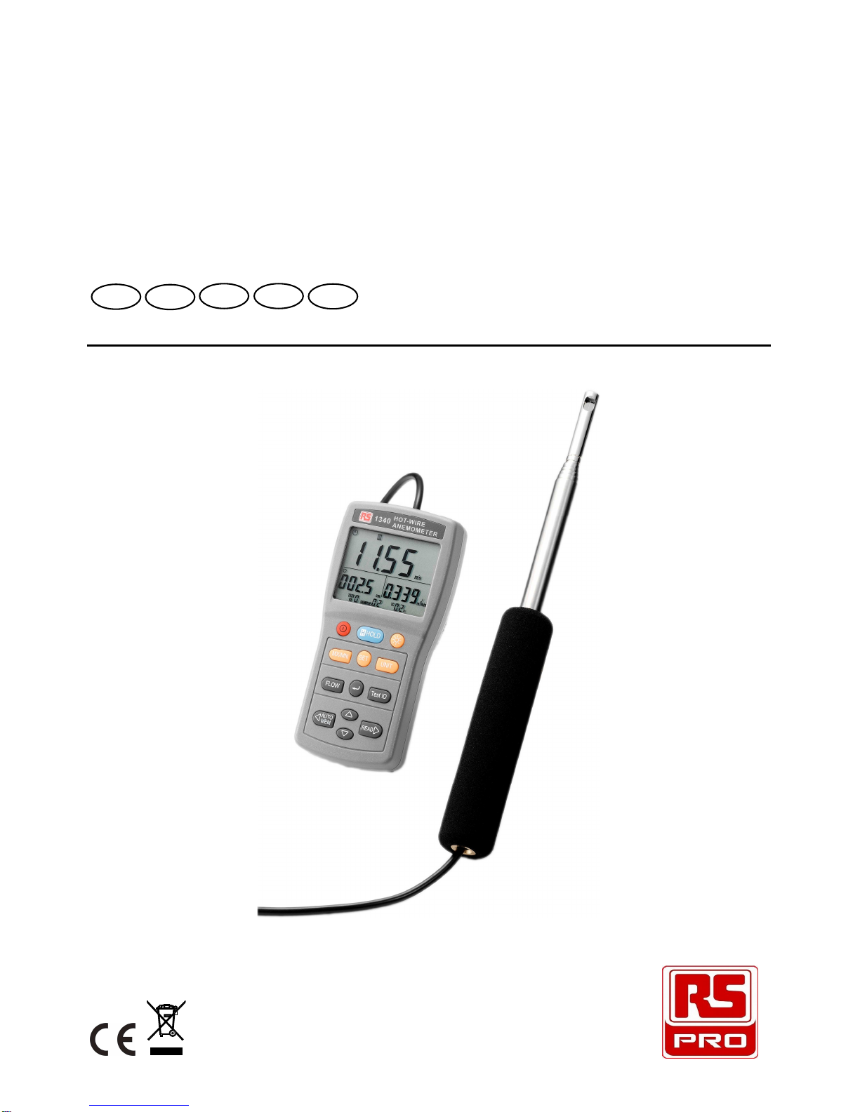
RS PRO RS-1340 User manual

RS Stock No. 724-4207
Instruction Manual
RS-1340
Hot Wire Anemometer
FREN IT DE ES

CONTENTS / EN
04/26/13 Version No. 01
CONTENTS
Title Page
1. SAFETY INFORMATION.............................................................1
2. INTRODUCTION..........................................................................2
3. SPECIFICATIONS.......................................................................3
4. PARTS & CONTROLS ................................................................4
4-1 Description of Parts & Control keys........................................4
4-2 Description of Display.............................................................6
5. MEASURING PROCEDURE .......................................................8
5-1 Getting Started .......................................................................8
5-2 Settings and Calibrations........................................................8
5-3 Air Velocity Measurement.....................................................10
5-4 Air Flow Measurement..........................................................10
5-5 MAX/MIN/AVG Recording Measurement .............................11
5-6 Air Velocity Manual Data Memory and Read Mode..............11
5-7 Air Flow Manual Data Memory and Read Mode...................11
5-8 Air Flow Auto Data Memory and Read Mode.......................12
5-9 Clearing Memory..................................................................12
6. MAINTENANCE.........................................................................13
6-1 Cleaning ...............................................................................13
6-2 Battery Replacement............................................................13

SAFETY INFORMATION / EN
04/26/13 Version No. 01 EN-1
1. SAFETY INFORMATION
The following symbol may appear on the instrument and in this instruction
manual:
Refer to Instruction Manual
CAUTION
When using the meter to check air flow, make certain that you can safely raise and hold
the meter while making measurements. Be especially careful when working on a
ladder.
Observe all necessary precautions so that the unit does not become caught in moving
machinery or touch any exposed electrical wiring.
DANGER
The meter is not designed for use in gas mixtures other than air. DO NOT use the unit
with corrosive or other dangerous or explosive gas mixtures.

INTRODUCTION / EN
04/26/13 Version No. 01
EN-2
2. INTRODUCTION
The Portable Air Velocity Meter is a lightweight instrument that can be used anywhere
to measure air velocity using the flexible telescoping probe, applications include
ventilation hood air velocity, clean rooms, OSHA compliance, ventilation ducts and
outlets, heating and air – conditioning, wind tunnels, product development, air – flow
research and mass – flow measurement in ducts.
Applications:
•HVAC system performance
•Commissioning
•Plant maintenance
•Critical environment certification
•Duct traverses
FEATURES:
•Fast response probe.
•Air flow volume.
•Instant / Avg /
3
2
V max flow measurement.
•Velocity m/s, f t/min, knots, km/hr, mph, Beaufort (Bft).
•Data hold & Maximum / Minimum / Average function.
•Manual data memory and read function (5 x 99 sets).
•Auto data memory and read function (5x 99 sets).
•LCD triple display.
•Auto power off function ON / OFF Time setting.
•Backlight function ON / OFF Time setting.
•Telescoping probe with flexible probe end.
•Simple and safe to use.

SPECIFICATIONS / EN
04/26/13 Version No. 01 EN-3
3. SPECIFICATIONS
Display : Triple display, 4 digit LCD reading.
Velocity Probe :
Range : 0 to 30 m/s (0 to 600 ft/min)
Resolution : 0.01 m/s (1 ft/min)
Accuracy : ±3% of reading ±1%FS
Duct Size :
Range : 1 to 635 cm in increments of 0.1 cm.
(1 to 250 inches in increments of 0.1 in.)
Volumetric Flow Rate :
Ranges : Actual range is a function of actual velocity, and duct size.
Warm up Time : < 1 minute
Response Time : < 2 seconds
Sampling Rate : One time per second.
Manual Data Memory Capacity : 5 x 99 sets.
Auto Data Memory Capacity : 5 x 99 sets.
Operation Temperature Range :
Meter : 0 to 50°C (32 to 122°F)
Probe : -10 to 60°C (14 to 140°F)
Storage : -20 to 60°C (-4 to 140°F)
Operation Conditions :Altitude up to 2000 metres.
Relative humidity up to 80%RH, non – condensing.
Power Supply : 6 pcs 1.5V size AAA battery.
Battery Life : Approx. 10 hours.
Probe Dimensions / Weight :
Wire length : 2.2 metre (7.2 ft)
Probe length : 1.2 metre (3.9 ft)
Probe diameter of tip : 9.0 mm (0.35 in.)
Probe diameter of base : 28.0 mm (1.1 in.)
Probe weight : 165 g (0.36 lbs)
Meter Weight / Dimensions : 235 g (0.52 lbs)
150 x 72 x 35 mm
5.9 x 2.8 x 1.4 inches
Supplied Accessories : Instruction manual, battery and Carry case.

PARTS & CONTROLS / EN
04/26/13 Version No. 01
EN-4
4. PARTS & CONTROLS
4-1 Description of Parts & Control keys
14
15
12
9
56
13
10
11
7
3
4
16
1
2
8
14
1
1. Air velocity sensor. (Measurement direction)
2. Flexible, telescoping probe.
3. Display.
4. Power key : Press power key to turn the meter on or off.
5. H HOLD key : Press H Hold key to freeze or unfreeze the display reading.
In H mode, press UNIT key to select the desired unit of display.
6. key : Press key to turn on and off the backlight.
7. MX/MN key : Press “MX/MN” key to select between the reading of Maximum, Minimum,
Average and Current record mode. Press “MX/MN” key for 2 seconds to
exit this mode.
8. SET key : Press “SET” key to enter setting mode.
•Flow setup mode.

PARTS & CONTROLS / EN
04/26/13 Version No. 01 EN-5
•Choosing a time constant mode.
•Choosing auto data memory interval time mode.
•Auto power off time setting mode.
•Backlight time setting mode.
•Air velocity calibration mode.
•Reset to factory default calibration value mode.
9. UNIT key : Press “UNIT” key to select the desired unit of measure.
10. FLOW key : Press “FLOW” key to select desired air velocity to determine the Air Flow.
•2/3V MAX : Use the maximum reading obtained to determine the 2/3V
MAX Air Flow.
•AVG : Use the average reading to determine the Air Flow.
•Use the current reading to determine the Air Flow.
11. ↵
↵↵
↵key : Enter / Exit a setting mode or store the displayed setting.
12.
Test ID key
: A group of samples. The statistics (maximum, minimum, average and count)
are calculated for each TEST ID. The total number of TEST IDs is 10.
Press “
Test ID
” key to select the desired TEST ID number from 0 to 9.
13.
AUTO MEM key :
In the setting mode, press this key to move the flashing cursor to the left.
In the TEST ID modes 0 to 4, press this key once to store the one data to memory.
In the TEST ID modes 5 to 9, press this key to start auto data memory mode, press
this key again to exit this mode.
14.
keys :
In the setting mode, press “
”keys to increase or decrease the displayed setting.
In the READ mode, press “
”keys to select increase or decrease the memory
address.
15. READ
key :
In the setting mode, press this key to move the flashing cursor to the right.
Press this key to enter the data memory READ mode, press this key again to exit
this mode.
16. Sensor protection cap.

PARTS & CONTROLS / EN
04/26/13 Version No. 01
EN-6
4-2 Description of Display
AIR VELOCITY DISPLAY
FLOW
SET UP
DISPLAY
AIR FLOW
DISPLAY
MEMORY DISPLAY
AIR VELOCITY DISPLAY :
: Auto power off indication.
H : Data hold indication.
SET : Setting mode indication.
REC : Record mode and current air velocity measured display indication.
REC MAX : Maximum air velocity measured display indication.
REC MIN : Minimum air velocity measured display indication.
REC AVG : Average air velocity measured display indication.
(The average of the last 30 samples)
Air Velocity Units :
knots
mile/hr : Miles per hour
km/hr : Kilometres per hour
ft/min : Feet per minute
Bft : Beaufort scale
m/s : Metres per second
FLOW SET UP DISPLAY :
: Round Duct diameter dimension indication.
X : Rectangle Duct X dimension indication.
Y : Rectangle Duct Y dimension indication.
Kf : K factor indication.
AREA : Duct Area indication.
m
2
: Square metres
ft
2
: Square feet
in : Inches
cm : Centimetre

PARTS & CONTROLS / EN
04/26/13 Version No. 01 EN-7
AIR FLOW DISPLAY :
2/3V MAX : 2/3V Maximum mode is selected indication.
AVG : Average mode is selected indication.
: Current mode is selected indication.
x 10 : Multiply reading by ten.
x 100 : Multiply reading by one hundred.
x 1000 : Multiply reading by one thousand.
ft
3
/min : Cubic feet per minute.
m
3
/min : Cubic metres per minute.
MEMORY DISPLAY :
TEST ID 0 – 4 : Manu data memory indication.
TEST ID 5 – 9 : Auto data memory indication.
SAMPLE : Data memory number address indication.
AVG
SAMPLE
: Total average data number indication.
M : Data memory indication, M display one time store one data into the memory.
R : Data read mode indication.
TC s : Average time constant indication.
INTV
m
s
: Auto data memory interval time indication.
+ -
: Low battery indication.

MEASURING PROCEDURE / EN
04/26/13 Version No. 01
EN-8
5. MEASURING PROCEDURE
5-1 Getting Started
1. Installing the Batteries
Insert six AAA batteries as indicated by the diagram located on the inside of the
battery compartment.
2. Extending the Probe
To extend the probe, remove the sensor protection cap, hold the handle in one
hand while pulling on the probe tip with the other hand. Do not hold the cable while
extending the probe as this prevents the probe from extending.
3. Using the flexible telescoping probe
The flexible telescoping probe contains the air velocity sensor. When usingthe probe,
remove the sensor protection cap then rotate or bend the flexible tube, make sure the
sensor windowis fully exposed and is facing upstream.
※
※※
※If in the right direction, the user will see the red-ink marking as following figure.
4. Retracting the Probe
To retract the probe, hold the handle in one hand while pushing on the probe tip with
the other hand. If you feel the probe antenna binding, pull gently on the probe tube
until the flexible tube section is retracted. Collapse the rest of the antenna by
pressing the probe tip and refit the sensor protection cap.
5-2 Settings and Calibrations
1. Flow Set Up mode
Press key to turn on the meter.
Press “UNIT” key to select the desired measurement unit.
Press “SET” key to enter the Flow Setup mode, the “ SET ” symbol is displayed.
There are 4 types : Round Duct (), Rectangle Duct ( ), Duct Area (AREA),
and K factor (Kf).
Press “
” and “
” keys to scroll through the choices and press “↵
↵↵
↵” key to confirm
your choice.

MEASURING PROCEDURE / EN
04/26/13 Version No. 01
EN-
9
If round duct is chosen, the “” symbol will displayed.
Use and keys to set the size (diameter) from 1.0 to 635.0 cm or 1.0 to
250.0 inches. Press “↵
↵↵
↵” key to store the value.
If rectangle duct is chosen, the “ X” symbol will displayed. Use and
keys to set the X – size of the duct, then press “↵
↵↵
↵” key to store the value and
advance to the next dimension, the “ Y” symbol will displayed. Use and
keys to set the Y – size of the duct, then press “↵
↵↵
↵” key to store the value.
If duct area is chosen, the “AREA” symbol will displayed. Use and keys to
set the value and decimal point of the duct area from 0.001 to 9999ft
2
or 929m
2
, then
press “↵
↵↵
↵” key to store the value.
If K factor is chosen, the “Kf” symbol will displayed. Use and keys to set
the value and decimal point of the K factor from 0.001 to 9999, then press “↵
↵↵
↵” key to
store the value.
Note : Kf is the number by which the meter multiplies the velocity measurement to
display volume.
Press “ SET ” key several times until the “ SET ” symbol disappears to exit the
setting mode.
2. Choosing a Time Constant mode
Press “SET” key twice to enter this mode, the “TC” symbol and the current time
constant are displayed.
Press
and
keys to scroll through the choices and press “↵
↵↵
↵” key to store the
choice. The choice for the time constant are : 1, 2, 3, 4, 5, 6, 7, 8, 9, 10, 15, 20, 25
and 30 seconds.
Press the “SET” key until the “ SET ” symbol vanishes to exit the setting mode.
The time constant is an averaging period. It is used to dampen the display. If you are
experiencing fluctuating flows, a longer time constant will slow down those fluctuations.
The average method is also referred to as a “moving average”.
3. Choosing a Auto Data Memory Interval Time mode
Press “SET” key three times to enter this mode, the “INTV” symbol and the current
interval time are displayed.
Press “
” and “
” keys to scroll through the log interval choices. The choice are : 1,
2, 3, 4, 5, 6, 7, 8, 9, 10, 15, 20, 25 and 30, seconds, and 1, 2, 3, 4, 5, 6, 7, 8, 9, 10,
15, 20, 25, 30 and 60, minutes. Press “↵
↵↵
↵” key to store the choice.
Press the “SET” key until the “ SET ” symbol vanishes to exit the setting mode.
4 Auto Power Off Time Setting mode
Press “SET” key four times to enter this mode, the “APO” symbol and the current auto
power off time are displayed.

MEASURING PROCEDURE / EN
04/26/13 Version No. 01
EN-10
Press “
” and “
” keys to set the desired auto power off time from 1 to 50 minutes
or to set to “– – m” to disable this function. Press “↵
↵↵
↵” key to store the setting.
Press the “SET” key until the “ SET ” symbol vanishes to exit the setting mode.
5. Backlighting Time Setting mode
Press “SET” key five times to enter this mode, the “bL” symbol and the current
backlight time are displayed.
Press “
” and “
” keys to set the desired backlight time from 1 to 50 seconds or to
set to “– – s” to disable this function. Press “↵
↵↵
↵” key to store the setting.
Press the “SET” key until the “ SET ” symbol disappears to exit the setting mode.
6. Air Velocity Calibration mode
Press “SET” key six times to enter this mode, the “USEr CAL no” symbol is displayed.
Press “
” or “
” keys to select “ ” symbol is displayed.
Press “↵
↵↵
↵” key to enter the air velocity zero calibration mode, the “CAL 0” symbol is
displayed.
Refit the sensor protection cap, until the air velocity reading is stable then press “↵
↵↵
↵”
key to store the zero air velocity reading, and enter the air velocity scale factor
calibration mode, the scale factor value is displayed.
Insert the meter probe into the calibration tunnel with the sensor window toward the
air flow. Secure the probe firmly with the velocity sensor placed where air speed is
known.
Press
,
,
and
keys to set the scale factor value until the display reading
reaches the desired value, then press “↵
↵↵
↵” key to store the scale factor value, the
“CAL PASS” symbol will display one second.
Press the “SET” key until the “ SET ” symbol vanishes to exit the setting mode.
7. Reset to Factory Default Calibration value mode
Press “SET” key seven times to enter this mode, the “dEF CAL” symbol is displayed.
Press “
” or “
” key to select “ ” or “ ”, select “ ” then press “↵
↵↵
↵” key to
reset the unit to factory default calibration value and exit the setting mode.
5-3 Air Velocity Measurement
1. Press key to turn on the meter.
2. The display will show the air velocity reading directly on the Air Velocity Display.
3. Press “UNIT” key to select the desired measurement unit.
4. Press “ H HOLD” key to freeze or unfreeze the display readings. In HOLD mode, the
“ H ” symbol is displayed press “UNIT” key to select another display unit reading.
5-4 Air Flow Measurement
AIR FLOW = (AIR VELOCITY) x (AREA)

MEASURING PROCEDURE / EN
04/26/13 Version No. 01
EN-
11
1. Press key to turn on the meter.
2. The display will show the air velocity reading directly on the air velocity display.
3. The flow type setting is displayed on the flow set up display.
4. Press “FLOW” key to select the desired 2/3V MAX mode, AVG mode or current mode.
If 2/3V MAX mode is chosen, the “2/3V MAX” symbol will be displayed. The meter will
use the maximum air velocity value obtained to determine the 2/3V MAX Air Flow.
If average mode is chosen, the “AVG” symbol will be displayed. The meter use air velocity
average value (the last 30 samples) obtained to determine the Average Air Flow.
If current mode is chosen, no symbol will be displayed. The meter will use the current
air velocity value obtained to determine the Current Air Flow.
5. The display will show the air flow reading directly on the Air Flow Display.
5-5 MAX/MIN/AVG Recording Measurement
1. Press “MX/MN” key to enter the recording mode, the “ REC ” symbol is displayed and
the auto power off function will automatically be cancelled.
2. Pressing “MX/MN” key to scroll the display through the maximum ( REC MAX ),
minimum ( REC MIN), average ( REC AVG ) and current ( REC ) air velocity
readings.
3. Press “ H HOLD” key to pause recording, the “ H ” symbol is displayed, press
“H HOLD” key again to resume recording.
4. Press “MX/MN” key for 2 seconds to exit this mode.
5-6 Air Velocity Manual Data Memory and Read Mode
TEST ID 0 Memory Mode :
1. Press “Test ID” key to select the “TEST ID 0” memory.
2. Press the “
AUTO MEM” key, to store one set of readings into the memory and
increments the “sample” display by 1, up to the max total memory size of 99 sets, the
“ M ” symbol will also be shown each time to confirm the storage.
3. Press “READ” key to enter READ mode, the display will show “ R ” symbol and the
memory address number. Press
or
key to select the desired memory address
number data for display. Press “READ” key again to exit the READ mode.
5-7 Air Flow Manual Data Memory and Read Mode
Memory Mode, TEST ID 1 ~ 4 only.
1. Press “Test ID” key to select the manual memory mode location. “TEST ID 1 ~ 4”.
2. Press “
AUTO MEM” key to store one set of readings into memory and increment the
“TEST ID sample” display by 1, the “ M ” symbol will also be shown each time to
confirm the storage. The maximum total memory size is 99 Manual sets.
If the flow parameters are change when in the read mode, the TEST ID will
automatically increment.

MEASURING PROCEDURE / EN
04/26/13 Version No. 01
EN-12
3. Press “
READ
” key to enter READ mode, the display will show “ R ” symbol and the
memory address number. Press “
” or “
” key to select the desired memory address
number data for display.
4. Press “MX/MN” key to scroll through each of the memory readings for the maximum
(MAX) air velocity and air flow and the memory address number, the minimum (MIN)
air velocity and air flow reading and the memory address number, and the average
(AVG) air velocity and air flow reading and the total average samples. Press the Test
ID to select each range in turn.
5. Press “READ” key again to exit the READ mode.
5-8 Air Flow Auto Data Memory and Read Mode
TEST ID 5 ~ 9 Memory Mode
1. Press “Test ID” key to select the “TEST ID 5” memory.
2. Press “
AUTO MEM” key to start auto data memory mode, “INTV” symbol and current
interval time are display, the “ M ” symbol flashes one time to indicate that one set of
data has been memorized. Total memory size is 99 sets per each IDs. Press
“
AUTO MEM” key again to exit this mode.
If the flow parameters are change when in the read mode, the TEST ID will
automatically increment.
3. Press “READ” key to enter READ mode, the display will show “ R ” symbol and the
memory address number. Press
or
key to select the desired memory address
number data for display.
4. Press “MX/MN” key to scroll through the memory of the maximum (MAX) air velocity
and air flow reading and the memory address number; the minimum (MIN) air velocity
and air flow reading and the memory address number; and the average (AVG) air
velocity and air flow reading and the total average samples. Press the Test ID to select
each range in turn.
5. Press “READ” key again to exit the READ mode.
5-9 Clearing Memory
1. Press key to turn off the meter.
2. Press and hold down the “
AUTO MEM” key then press key to turn on the meter to
enter clear memory mode, “CLr no” symbol is displayed.
3. Press “Test ID” key to select the desired “TEST ID” to be clear.
4. Press “
” key to select the “ ” symbol.
5. Press “
AUTO MEM” key to clear the memorized data. repeat steps 2 to 5 if required.
6. Press “↵
↵↵
↵” key to exit the clear memory mode.

MAINTENANCE / EN
04/26/13 Version No. 01
EN-
13
6. MAINTENANCE
6-1 Cleaning :
Periodically wipe the case with a damp cloth and mild detergent.
Do not use abrasives or solvents. Clean and dry as required.
6-2 Battery Replacement :
Note: The condition of the battery should be checked prior to use and changed if
necessary. The LCD display will show “
+ -
” symbol when the battery power
is not sufficient for accurate testing.
1. Remove discharged battery and insert new one, respecting the correct polarity.
2. Dispose of the removed batteries is accordance with local regulations.
3. If the instrument is likely to remain unused for a long period it is advised to
remove the batteries.
Table of contents
Other RS PRO Measuring Instrument manuals

RS PRO
RS PRO RS-1260 User manual

RS PRO
RS PRO RS-95 User manual

RS PRO
RS PRO LCR-6000 Series User manual

RS PRO
RS PRO IM-191 User manual

RS PRO
RS PRO SLM 1353M User manual

RS PRO
RS PRO RSST-2000 Series User manual

RS PRO
RS PRO RS 155B User manual

RS PRO
RS PRO ILM 1332A User manual

RS PRO
RS PRO ICM A5 User manual

RS PRO
RS PRO RSPRO-P30R User manual

RS PRO
RS PRO ICM 134 User manual

RS PRO
RS PRO RS-5200 User manual

RS PRO
RS PRO RS-320B User manual

RS PRO
RS PRO 877-1791 User manual

RS PRO
RS PRO RS-1151 User manual

RS PRO
RS PRO 123-8776 User manual

RS PRO
RS PRO IM-195 User manual

RS PRO
RS PRO ICM 20 User manual

RS PRO
RS PRO RS-96 User manual

RS PRO
RS PRO 2377271 User manual