Electra Light CITY LED User manual

CITY LED 96*10W-RGBW User’s Manual CITY LED 96*10W-RGBW User’s Manual
LED Washer Series
User’s Manual
AutoRun
DMX
512
PROGRAM
www.electralight.com.br
CITY LED 96*10W – RGBW – 4in1
User’s Manual
CITY LED 96*10W-RGBW User’s Manual CITY LED 96*10W-RGBW User’s Manual
SETUP AND OPERATION
Power Supply:
This fixture has an auto-switching power supply that can accommodate a wide range
of input voltages. But before plugging the units in, make sure that the source voltage
in your area matches the required voltage for your units. You should be sure that your
unit voltage matches the wall outlet voltage before attempting to operate your units.
DMX Cable Requirements:
The fixture can be controlled via standard DMX-512 protocol. It has 6 DMX channels
which can be set up on LED display panel. You need to use a standard 3-pin XLR
connector for data input and output If you are using your own cables, be sure to use
standard two conductor shielded cable. Your cables should be made with a male and
female XLR connector on either end of the cable. Also remember that DMX cable
must be daisy chained and cannot be split.
To ensure proper DMX data transmission, when using several DMX units, try to use
the shortest cable path. The order in which units are connected in a DMX chain does
not influent the DMX addressing. For example; a unit assigned a DMX address as 1
may be placed anywhere in a DMX line, at the beginning, or at the and, or anywhere
in the middle. When a unit is assigned a DMX address as 1, the DMX controller
understands to send DATA assigned to address 1 to that unit, no matter where it is
positioned in the DMX chain
Cabling the Fixtures
The fixtures need to be connected to each other with standard DMX data cables as
shown below: LED Washer SERIER User’s Manual
In DMX Controller mode, at the last fixture in the chain, the DMX output has to be
connected with a DMX terminator. This prevents electrical noise from disturbing and
corrupting the DMX control signals
The DMX terminator is simply an XLR connector with a 90 - 120Ω(ohm) 1/4 watt
resistor
Connected across pins 2 and 3 of a male XLR connector (DATA+ and DATA-). This
terminator is then plugged into the output socket on the last fixture in the daisy chain
to terminate the line Using a cable terminator will decrease the possibilities of erratic
behavior. The connections are illustrated below.
Memo
:
DATE REPAIR RECORD
.
2.
.

CITY LED 96*10W-RGBW User’s Manual CITY LED 96*10W-RGBW User’s Manual
SAFY INSTRUCTIONS
Please keep this User Guide for future consultation. If you sell the unit to another
user, be sure that they also receive this instruction booklet.
Always make sure that you are connecting to the proper voltage, and that the
line voltage you are connecting to is not higher than that stated on the decal or
rear panel of the fixture.
This product is intended for indoor use only!
To prevent risk of fire or shock, do not expose fixture to rain or moisture.
Make sure there are no flammable materials close to the unit while operating.
The unit must be installed in a location with adequate ventilation, at least 20in
(50cm) from adjacent surfaces. Be sure that no ventilation slots are blocked.
Always disconnect from power source before servicing or replacing fuse and be
sure to replace with same fuse size and type.
Secure fixture to fastening device using a safety chain. Never carry the fixture solely
by its head. Use its carrying handles.
Maximum ambient temperature (Ta) is 104 °F (40 ° C). Do not operate fixture at
temperatures higher than this.
In the event of a serious operating problem, stop using the unit immediately. Never
try to repair the unit by yourself. Repairs carried out by unskilled people can lead to
damage or malfunction. Please contact the nearest authorized technical assistance
center. Always use the same type spare parts.
Make sure the power cord is never crimped or damaged.
Never disconnect the power cord by pulling or tugging on the cord.
Avoid direct eye exposure to the light source while it is on.
Warning!
Verify that the voltage select switch on your unit matches the line voltage applied.
Damage to your fixture may result if the line voltage applied does not match the
voltage indicated on the voltage selector switch. All fixtures must be connected to
circuits with a suitable Earth Ground.
LED DISPLAY AND KEYSETUP
The unit has a 4-digit LED display to configure its functions. This LED display has
four touch buttons: <MENU>, <UP>, <DOWN> and <ENTER>.
You can access these functions by using the four bottons. Here are functons of these
buttons.
<MENU>: this button is used to access the
menu or to return to a previous menu
option.
<UP>: this button is used to scroll through menu
options in descending order.
<DOWN>: this button is used to select and store the current menu or option within a
menu.
<ENTER>: this button is used to selects menu option.
Normally, the LED will display current DMX address code, as like: “DMX
Address: 001”. Press<MENU> to enter the main menu; press <UP> or <DOWN> to
scroll in the menu or submenu options; Press <ENTER> to confirm your selection.
Any time press and hold <UP> or <DOWN>,the value will rapidly change and stop
when released. Once the value is set, press <ENTER> again to save and exit to the
main menu.
Turn on the fixture, and after initialization, it is ready for setting and working.
Please see the following table for setting information.
.
Thank you very much for your purchasing this device,
please
read
these instructions carefully, it includes important information about
the installation,
usage and maintenance of the product.
CITY LED 96*10W-RGBW User’s Manual CITY LED 96*10W-RGBW User’s Manual
LED Washer – RGBW
1. Technical Parameter:
Voltage: 110-240/50-60Hz
Model: 96*10W 4-in-1 RGBW LED;
DMX Channels: 4/8CH/12CH
Function: DMX, sound control, built-in program, M/s
And program chooses color, change color.
Size: 640×410×820mm
N.W:20KG;
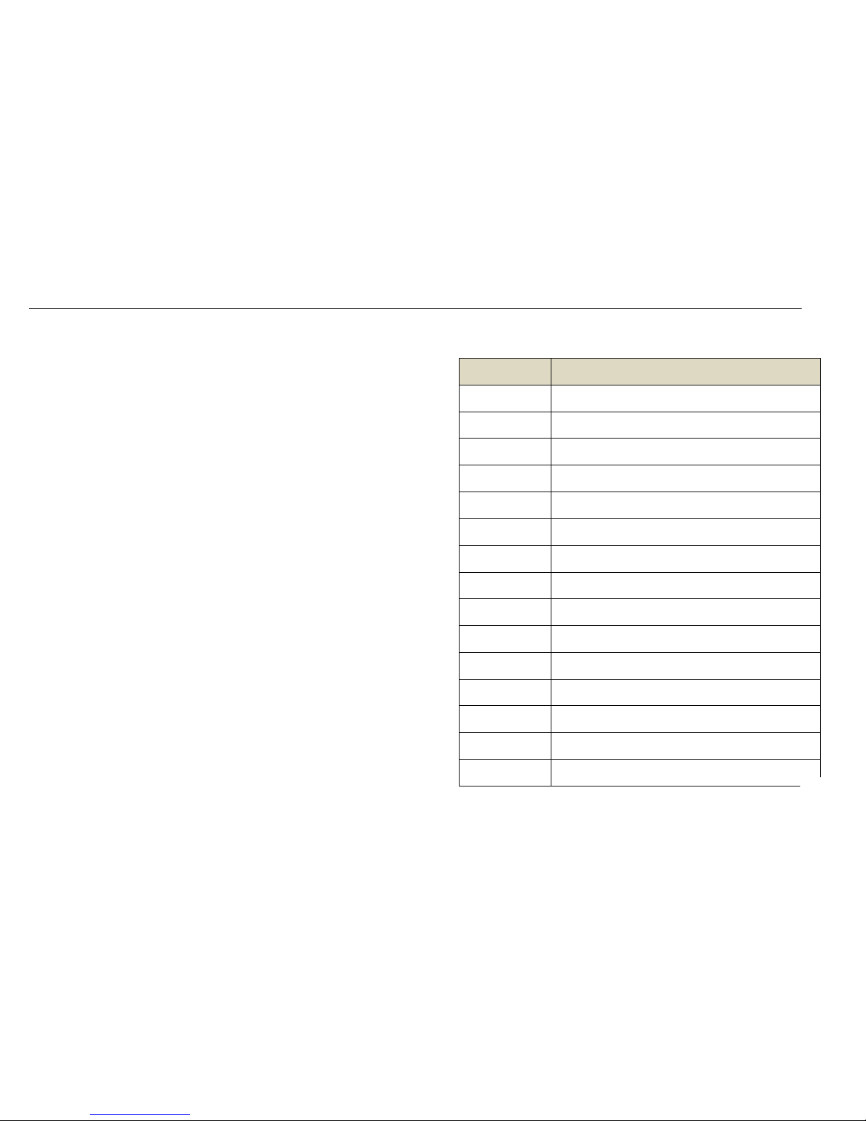
2.DISPLAY PANEL:
(need to press enter to confirm and save the function you choose)
No. LED display Function
1 A001 4 DMX channel,(001—512)
2 H001 8 DMX channels,(001—512)B、C key change speed
3 h001 12DMX channels,(001—512)B、C key change speed
4 CC50 7 color jump change(00—99)B、C key change speed
5 CP50 7 color pulse change,(00—99)B、C key change speed
6 DE50 7 color fade(00—99)B、C key change speed
7 DEDE 7 color Music control(00—99)B、C key change speed
8 R255 Red color change(000—255)B、C key change speed
9 G255 Green color change(000—255)B、C change speed
10 B255 Blue color change(000—255)B、C key change speed
11 n255 Flash(000—255 ,B、C key change speed
3. DMX Channels tables:
1).DMX 512:4 channels function:
Channel Function Instruction
CH1 Red Red dimmer
CH2 Green Green dimmer
CH3 Blue Blue dimmer
CH4 White White dimmer
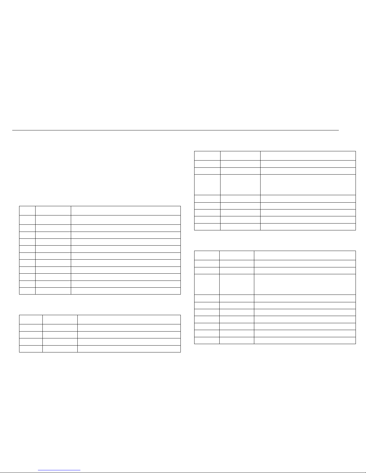
2).DMX512:12 channels function
Channel Function detail
CH1 Total dimmer R、G、B、Main dimmer
CH2 Total flash R、G、B、Main strobe
CH3
Function
0—50:DMX512;51—99:jump change;100—150:
gradually change;151—200:fade ;201—250:pulse
change;251—255:music control
CH4 Speed Function speed
CH5 Red dimmer Red dimmer
CH6 Green dimmer Green dimmer
CH7 Blue dimmer Blue dimmer
CH8 White dimmer White dimmer
3) DMX512:12 channels function
Channel Function detail
CH1 Total dimmer R、G、B、Main dimmer
CH2 Total flash R、G、B、Main strobe
CH3
Function
0—50:DMX512;51—99:jump change;100—150:gradually
change;151—200:fade ;201—250:pulse change;
251—255:music control
CH4 Speed Function speed
CH5 Red1 dimmer Red dimmer
CH6 Green1 dimmer Green dimmer
CH7 Blue1 dimmer Blue dimmer
CH8 White1 dimmer White dimmer
CH5 Red2 dimmer Red dimmer
。。。。 。。。。 。。。。
.
Other Electra Light Dj Equipment manuals


