Electric Druid FilterFX Project Instructions for use

Electric Druid FilterFX Construction Guide www.electricdruid.net
Electric Druid FilterFX Project
Overview
The FilterFX project uses the Druid STOMPLFO to control a 12dB/oct state variable filter.A state
variable filter is chosen because this filter design offers highpass, bandpass, and lowpass outputs
Overview 1
Build Instructions 3
Populate the PCB 3
Power protection diode 3
1N4148 Diode 3
Resistors 3
Cup of tea and soldering check 4
IC sockets 4
Regulator 4
Transistors 4
Ceramic bypass capacitors 4
Film capacitors 4
Electrolytic capacitors 4
Vactrols 5
Second cup of tea and Power Test 5
Drilling the enclosure 5
Potentiometers, Switches, and LEDs 5
Install ICs 6
Off-board wiring 7
Optional Sync Input 7
Optional Expression pedal / CV input 8
Adjustments and final testing 8
Bill of Materials 9
Offboard components 10
Component choices and substitutions 10
Resistors 10
Changing the LED resistors 10
Capacitors 10
Transistors 10
Op-amps 11
Diodes 11
Vactrols/optocouplers 11
Ideas for potential upgrades or customizations 11
Adding CV inputs 11
Adding further expression pedal inputs 11
Page 1

Electric Druid FilterFX Construction Guide www.electricdruid.net
which gives us the greatest range of different effects.The LFO offers eight waveforms, including two
random waveforms.
Furthermore, the PCB provides for addition of an expression pedal to allow the filter to be used
like a wah pedal (but don’t expect a replacement for your Clyde McCoy - this is a whole different
thing!).The expression pedal can be used as well as the LFO modulation, or with Depth at zero, by
itself.There is also a Sync input for the LFO which allows the LFO to be kept in time with an
external clock from a sequencer, drum machine, or another LFO.
Page 2

Electric Druid FilterFX Construction Guide www.electricdruid.net
Build Instructions
You’re advised to have a read through of these instructions before starting work on the PCB.To
keep these instructions reasonably brief, it is assumed that you know how to orientate common
components.
Populate the PCB
The board should be populated in order from smallest components to tallest.The BOM on page 8
is arranged in this order, so start at the top and work your way down.You can tick off each line in
the “Done?” column on the far right.
If you hold the PCB with the “FilterFX” title and “electric druid” logo the right way up, you’ll see
that the board is shaped like a “T”. The top bar of the T has the Sync Input circuit, the vactrols, and
the StompLFO chip. Below them in the middle of the T, we have the filter op-amp and capacitors.
Next we have the toggle switches, with resistors between them, including the three resonance
selection resistors which are inside a white box. Finally, at the foot of the board is the input/output
op-amp and its associated resistors and capacitors.
Power protection diode
Start by installing the 1N5817 diode in the top-left arm of the PCB.This protects the PCB against
reverse voltage, so be sure to check the orientation carefully.
1N4148 Diode
Next do the 1N4148 diode.This protects the Sync input, and needs to be the right way around, so
again check the orientation. It’s the furthest left component on the PCB.
Resistors
Next come the resistors.We do them in value order, from the lowest to the highest.
•47R resistor x 1 - top left, next to the 1N5817 you just did.
•220R resistor x 1 - on the bar of the T, top far right
•470R resistor x 3 - two in the centre between the vactrols, one far right between the switches
•560R resistor x 1 - between the switches
•1K resistor x 2 - both left of the lowest TL072 op-amp
•2K2 resistor x 1 - on the bar of the T, top far right
•4K7 resistor x 2 - both together at the edge of the board, centre-left
•10K resistor x 6 - three together to the right of the lowest TL072 op-amp, one in the Sync Input
circuit top left, one left of the STOMPLFO chip, one in the resonance resistors box between the
switches.
•20K resistor x 1 - between the switches, centred
•100K resistor x 2 - between the switches, one is the resonance resistors box, one not
•120K resistor x 2 - one below each vactrol
•680K resistor x 1 - between the switches, in the resonance resistors box
•2M2 resistor x 2 - one to the left of, and one above the lowest TL072
Page 3

Electric Druid FilterFX Construction Guide www.electricdruid.net
Cup of tea and soldering check
When you’ve finished doing the resistors, stop and have a cup of tea and spend a few minutes
looking over your solder joints and making sure everything’s ok so far.
IC sockets
All three 8-pin DIP sockets are identical.The two for the op-amps are on the centre line of the
board with the notch pointed down, and the third one for the StompLFO is in the top-right corner
of the PCB with the notch pointing left. It helps to solder only a single pin or a couple of corner
pins first, and then give the socket a check. If it’s sitting correctly and orientated the right way
around, you can solder the rest of the pins. If not, it’s much easier to adjust it with only two pins
soldered. Removing IC sockets from plated-through-hole PCBs like this one is difficult and not
recommended.
Regulator
The 78L05 +5V regulator REG1 is in the top left of the centre of the board, just below the electric
druid logo. Be sure to line up the flat side and the curved side with the markings on the PCB.
Don’t mix it up with the similar-looking transistors.
Transistors
There are two 2N3904 transistors, both along the top of the board.TR1 is to the right of the
right-most vactrol. TR2 is in the top-left in the Sync Input circuit. Both are marked with an
“n” (for “NPN”).Again, be sure to line up the flat side and the curved side with the markings on
the PCB.
Ceramic bypass capacitors
There are three 100n ceramic bypass capacitors, all at the top of the board.Two are beside the
STOMPLFO chip, and one more one is by the 5V regulator.These are not the fat 100n film cap
towards the bottom left. Don’t mix them up! (although it’ll still work if you do).
Film capacitors
There are four film caps in the FilterFX.You can use capacitors with either 0.2”/5mm or 0.3”/
7.5mm lead spacing.You can’t use capacitors with 0.1”/2.5mm lead spacing - those two holes are
connected together!
•10n (103, 0.01u) capacitor x 2 - centre left and centre right, either side of the TL072
•100n (104, 0.1u) capacitor x 1 - bottom left
•470n (474, 0.47u) capacitor x 1 - bottom right, by the smiley face :)
Electrolytic capacitors
There are only three of these, but you need to watch the polarity.
•47u capacitor x 2 - these are next to the two vactrols.
•100u capacitor - top left, just left of the electric druid logo
Page 4

Electric Druid FilterFX Construction Guide www.electricdruid.net
Vactrols
There are two Xvive VTL5C3 optocouplers (“vactrols” or “optos”).They’re the massive things in
the middle and they’re clearly marked on the silkscreen, so you can’t miss ‘em! Make sure you get
them the right way around.The end of the vactrol marked LED has a + symbol, and the legs are
close together on a 0.1”/2.5mm spacing.The end of the vactrol marked LDR or CELL has a wider
spacing of 0.2”/5mm.
Second cup of tea and Power Test
Have a break. If you’ve got this far, you deserve it.
Also, you need to be on top form for the next part -
testing the power.At this stage, you can power the
board up and check the voltages with a multimeter.
Don’t put the chips in yet.There should be 9V power
across pins 4 and 8 of each op-amp socket.There
should be 5V power across pins 8 and 1 of the
STOMPLFO chip socket.
Check the soldering over one last time, since after
you fit the pots, it’s a lot more difficult to get to
some of the PCB.
Ok, now we take a detour…the reason why will be-
come apparent shortly.
Drilling the enclosure
The PCB is designed to be mounted in landscape format in a Hammond 1590BB enclosure or
equivalent.The board is held in place by the pots and switches.
You can download the FilterFX drilling template from the Electric Druid website.
Note that the power input jack is a very tight fit if placed above the PCB as shown on the drilling
template. It’s possible to do, but the hole needs to be as close to the lid of the box as you dare.
If you don’t fancy doing it all, for now you only need to drill the front panel holes for the pots, the
switches, and the LEDs.
Potentiometers, Switches, and LEDs
Note that the pots, switches, and LEDs mount on the back (solder-side) of the PCB!
First, break the small anti-rotation tabs off the pots with pliers.
Something is required to prevent the pots from shorting out the back of the PCB. Many things
work; all the way from expensive pot dust covers, to a couple of pieces of insulation tape stuck on
Page 5

Electric Druid FilterFX Construction Guide www.electricdruid.net
the back of the pots, to a piece of cardboard stuck between the board and the pots. My current
favourite solution is to cut a piece of stiff overhead transparency plastic and slide it between the
PCB and the pots.This can be done after soldering the pots, but pot dust covers would need fitting
now.
The best way to fit the pots, switches, and LEDs is to have the enclosure ready and drilled.The
components can then be fitted into the PCB (but not soldered) and then the board fitted into the
enclosure. Check the flat side of the LEDs matches the flat side on the silkscreen print. Once the
LEDs are in the board, bend their legs outwards a little to stop them falling out of the PCB while
you fit it. It’s a good idea to tighten the pot and switch nuts down a bit to ensure they are properly
located in the enclosure. Once you’re sure everything’s in place, it’s a simple job to solder the con-
nections, and you’re safe in knowledge that when you next try to fit it everything will be be per-
fectly lined up with your enclosure.
The two switches have a groove in the threads which can be matched with the notch shown on
the silkscreen. In theory the orientation of the switches shouldn’t matter, but I admit I haven’t
dared to try doing it the wrong way around yet since desoldering the switches if it doesn’t work
would be very difficult!
Install ICs
If the voltage check was ok, you can install the three chips; two dual op-amps, and the Electric
Druid STOMPLFO chip.
The PCB is done! Well done!
Page 6
Electric Druid FilterFX Construction Guide www.electricdruid.net
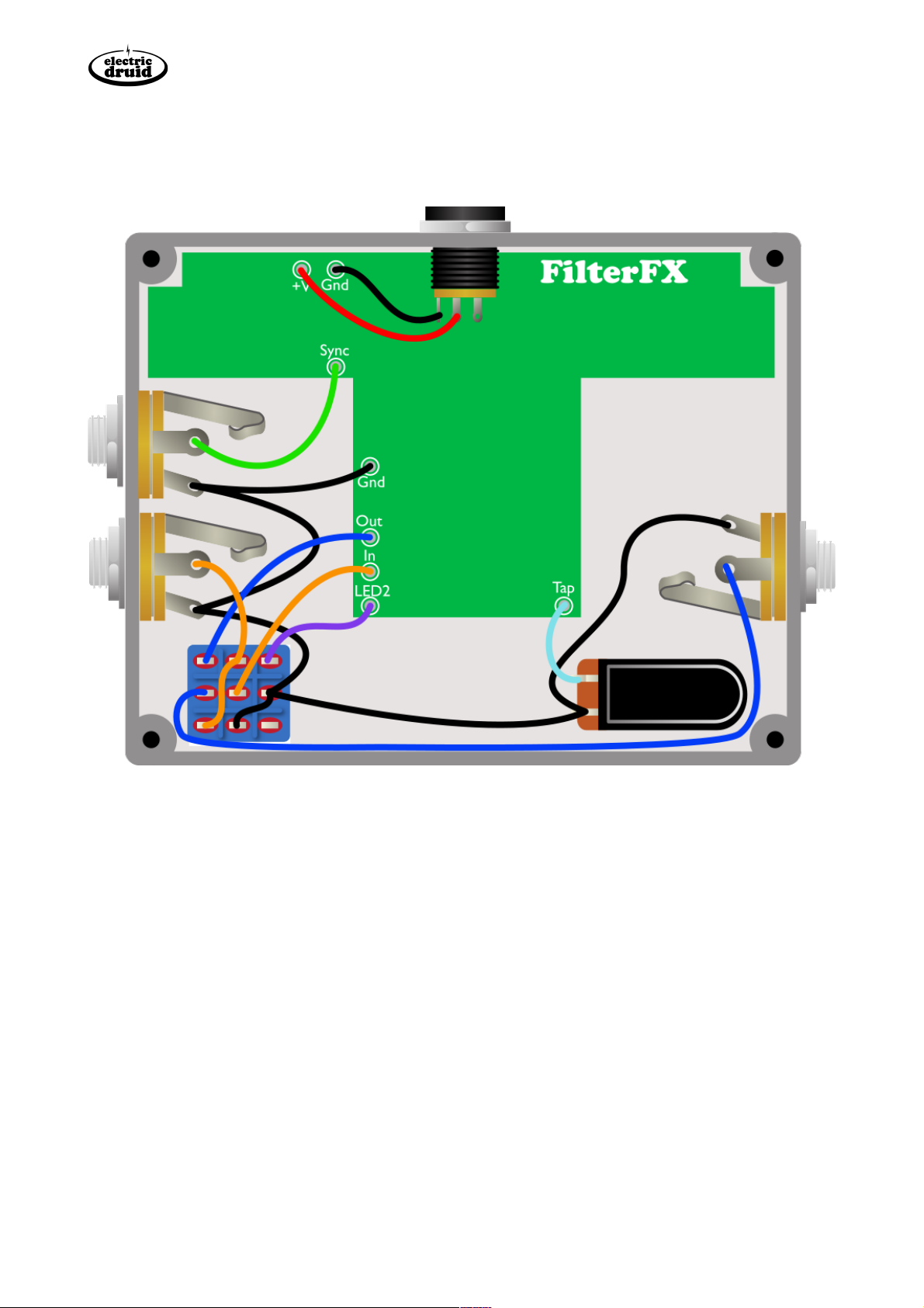
Off-board wiring
The off-board wiring for the FilterFX is fairly complex - take your time and break it up into
sections. In fact, you don’t even have to do it all if you don’t want to, but we’ll come to that in a
moment.
There’s a power input and mono 1/4” jacks for the input, the output, and the sync input.The two
switches are a 3PDT stomp switch to provide true bypass switching and control the bypass LED to
show you the on/off status of the effect and a SPST momentary foot switch for the tap tempo.
Optional Sync Input
The Sync Input is optional. If you include it, it allows you to synchronise the LFO to incoming puls-
es from a sequencer, analog synth, or drum machine.The Sync input jack is shown on the diagram
above, but if you don’t need it, you can just ignore it and wire the ground direct from the input jack
to the PCB.
Page 7
Electric Druid FilterFX Construction Guide www.electricdruid.net
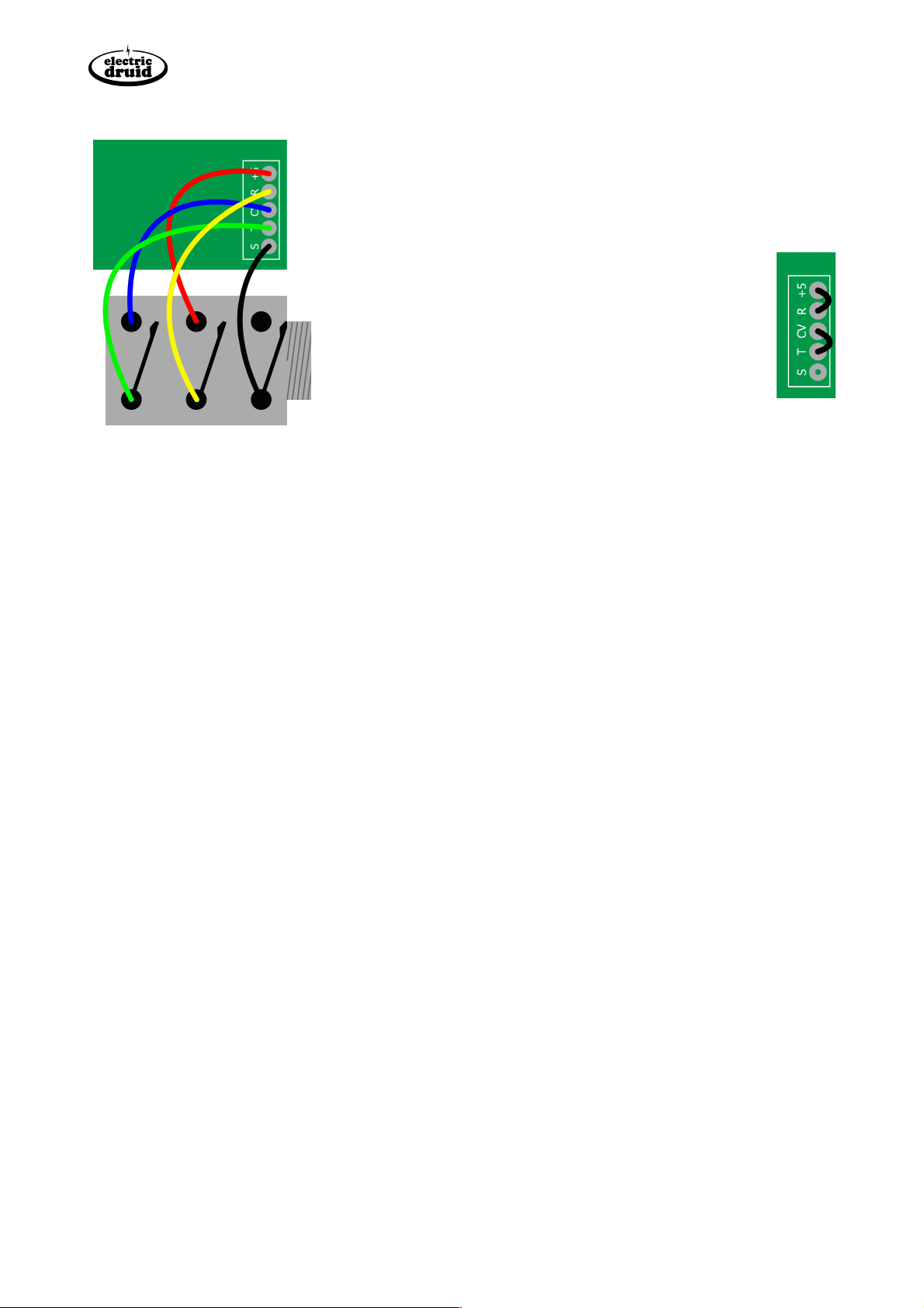
Optional Expression pedal / CV input
The optional Expression/CV input allows you to connect an
expression pedal or CV source to replace the Frequency control
of the filter. A stereo/TRS jack with normally closed contacts
should be used.The wiring required is shown on the left. Note the
T,R,S pads connect to Tip, Ring, and Sleeve connections on
the jack. +5 and CV provide the normally connections
for Ring and Tip respectively.
If you don’t want the Expression/CV input, there are two
jumpers required, shown on the right.They connect the
pads marked R/+5 and T/CV.
Adjustments and final testing
Ok, it’s the moment of truth. Power it up and plug it in.With a bit of care and attention, you should
now have a working FilterFX pedal! It doesn’t need any trimming, but the knobs cover a wide
range and you’ll need to learn how to adjust things for best effect and to your personal taste.
You’re done! Congratulations and enjoy your new pedal!
PS:We appreciate any corrections, feedback, suggestions, or thoughts you have about this pedal or any
other Druid project. Please get in touch through the website.Thanks!!
Page 8

Electric Druid FilterFX Construction Guide www.electricdruid.net
Bill of Materials
Additionally, you will need some/all of the offboard components listed on the
next page.
Order
Ref
Description
Value
Quantity
Done?
1
D1
Polarity Protection Diode
1N5817
1
2
D2
Signal Diode
1N4148
1
3
R23
1% Metal film resistor
47R
1
4
R24
1% Metal film resistor
220R
1
5
R16, R17, R18
1% Metal film resistor
470R
3
6
R14
1% Metal film resistor
560R
1
7
R1, R15
1% Metal film resistor
1K
2
8
R25
1% Metal film resistor
2K2
1
9
R20, R21
1% Metal film resistor
4K7
2
10
R4, R6, R9, R10, R19, R22
1% Metal film resistor
10K
6
11
R5
1% Metal film resistor
20K
1
12
R7, R13
1% Metal film resistor
100K
2
13
R11, R12
1% Metal film resistor
120K
2
14
R8
1% Metal film resistor
680K
1
15
R2, R3
1% Metal film resistor
2M2
2
16
TL072, TL072, STOMPLFO
IC sockets
8-pin DIP
3
17
REG1
+5V Regulator
78L05
1
18
TR1, TR2
NPN Transistor
2N3904
2
19
C7, C9, C10
Ceramic capacitor
100n
3
20
C1
Film capacitor
100n
1
21
C2, C3
Film capacitor
10n
2
22
C4
Film capacitor
470n
1
23
C5, C8
Electrolytic capacitor
47u
2
24
C6
Electrolytic capacitor
100u
1
25
V1, V2
VTL5C3 Optocoupler
VTL5C3
2
26
VR1, VR2, VR3, VR4
10K Lin Potentiometers
10K Lin
4
27
SW1, SW2
Salecom 3-way switch
T812
2
28
LED1, LED2
Indicator LEDs
2
28
Unmarked
Pot dust covers or plastic
29
IC1, IC2
Dual audio op-amp
TL072
2
30
uP1
PIC 16F18313
STOMPLFO
1
Page 9

Electric Druid FilterFX Construction Guide www.electricdruid.net
Offboard components
Note that the BOM above doesn’t include offboard components. These are a matter of taste, but
the basics are listed below.
•Enclosure, PCB fits Hammond 1590BB or Eddystone 29830PSLA
•Mono 1/4”/6.35mm Input jack
•Mono 1/4”/6.35mm Output jack
•Optional stereo (TRS) 1/4”/6.35mm Expression pedal jack - must have switched contacts to
allow normal operation.
•Optional Sync input jack - The PCB allows space for a 1/4”/6.35mm mono jack, but you may
prefer a 3.5mm jack to allow easy synchronisation with a Eurorack synth, for example.
•Stomp switch, 3PDT for Bypass switching
•Stomp switch, SPST momentary, for Tap Tempo
•Power Input socket, 2.1mm. Sockets with an external nut are much easier, since you can wire
them and test the board without it in the enclosure.
•4 x Knobs
Because of the current drain of this pedal, we don’t recommend using batteries instead of a power
adaptor. Ok, maybe, if you’ve got 9V rechargeables.
Component choices and substitutions
Very few of the components in the circuit are especially critical and a unit built with non-ideal
components will likely still work fine.
Resistors
In the interests of lowest noise, we recommend you use 1% metal film resistors.
Changing the LED resistors
Depending what LEDs you use, you may find the LEDs are too bright or not bright enough for
your taste.The Bypass LED is powered from the 9V supply with a 1K series resistor (R15, bottom
left below the 2M2).The LFO LED is powered from 5V with a 470R resistor (R16, furthest right of
the resistors between the switches).
Capacitors
Use good quality polypropylene or polyester film capacitors.The board allows either 0.2”/5mm or
0.3”/7.5mm lead spacing for the film capacitors.The two integrator capacitors C2 and C3 are
especially important, since they’re crucial to the filter’s operation.The circuit is unlikely to be able
to achieve self-oscillation at high resonance settings because of the differences in the optos, but
close matching between the filter caps will help increase the possibility.
Transistors
Transistor choice is not critical. Any medium gain, low noise NPN device will work.The board
expects a transistor with the EBC pinout, like the 2N3904. If you only have transistors with the
alternative CBE pinout like the BC547, you can fit the transistor back-to-front.
Page 10
Electric Druid FilterFX Construction Guide www.electricdruid.net
Op-amps
Similarly, op-amp choice is not critical. Choose any 8-pin dual audio op-amp with the standard
pinout.TL072, LF353, or MC1458 will all work. Many more audiophile options are also possible!
Diodes
The power protection diode suggested is 1N5817.This diode is recommended because of its low
voltage drop at the sort of currents the pedal draws. Others will work but may reduce headroom
a little more.
The 1N4148 diode can be replaced with other small signal silicon diodes. 1N914 is a direct
replacement and can be considered identical.
Vactrols/optocouplers
The VTL5C3 vactrol optocouplers can be replaced with either other types of vactrol (which might
change response times and other behaviour - which could be good or bad, depending on your
objectives) or could be replaced with home-made opto’s made from and LDR and an LED stuck
together and wrapped with something to keep the light out (heatshrink or even electrical
insulation tape). R11 and R12 (both 120K) limit the dark resistance of the opto’s to something
reasonable, and you may find with other options that you need to change their values.
Ideas for potential upgrades or customizations
Adding CV inputs
Since the Electric Druid STOMPLFO chip operates using 0-5V control voltages like many other
Druid chips, it is possible to add CV control of the Offset(Frequency), Rate, Depth, or Waveform
controls.
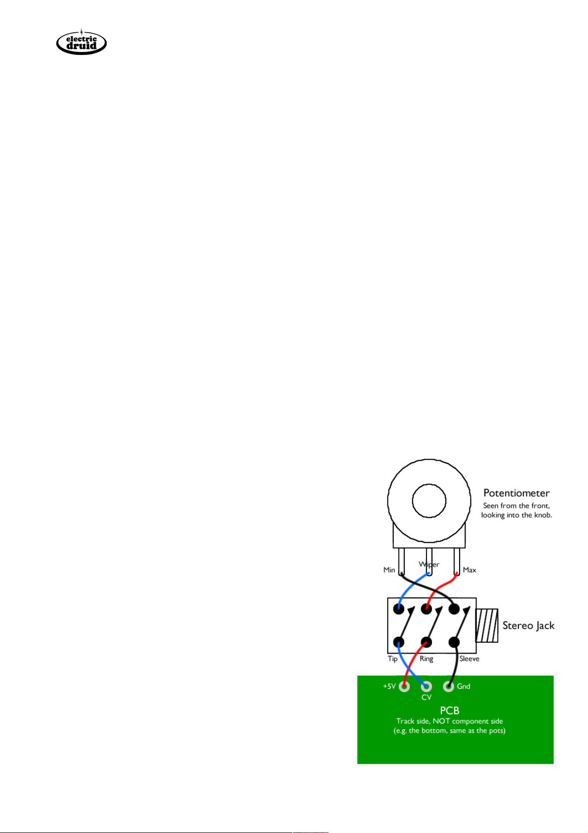
Adding further expression pedal inputs
The circuit includes an expression pedal input to replace the
filter’s Frequency control, but a similar scheme can be used
for the other controls if required.
A normally-closed stereo/TRS jack socket should be wired
in, so the front panel control can be used when an
expression pedal is not inserted.
The typical expression pedal wiring is for the Sleeve to be
grounded, the Ring to carry the reference voltage, and the
CV return on the tip.The diagram shows how this wiring
relates to the PCB, the jack, and the pot.
However, this is not the only possible wiring,
and your expression pedal may not be this way!
Page 11
Table of contents
Other Electric Druid Music Pedal manuals


