Electric Druid Flangelicious Instructions for use

Electric Druid Flangelicious Flanger Project
(Using either 4KNOBFLANGE or MULTIFLANGE chips)
Overview!2
Build Instructions!2
Populate the PCB!2
1N4148 Diodes!2
Resistors!2
Cup of tea and soldering check!3
Power protection diode!3
IC sockets!3
Regulator!3
Transistor!3
Ceramic bypass capacitors!3
Film capacitors!3
Electrolytic capacitors!4
Preset resistors (Trimmers)!4
Second cup of tea and Power Test!4
Potentiometers!4
Install ICs!5
Off-board wiring!6
Adjustments and final testing!6
Bill of Materials!8
Offboard components!9
Component choices and substitutions!9
Ideas for potential upgrades or customizations!10
Adding CV inputs!10
Adding Expression pedal inputs!10
Adding more switches and options!10
Flangelicious Construction Guide
www.electricdruid.net
Page 1
Overview
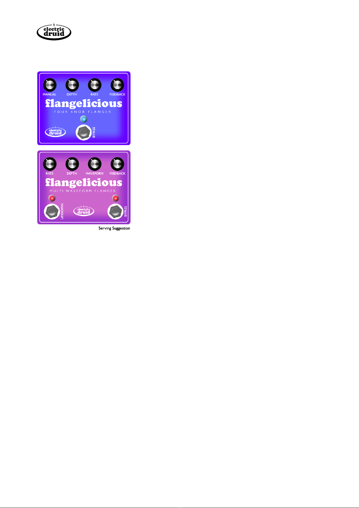
The Flangelicious flanger project comes in two flavours,
depending on which FLANGE chip you fit - either the 4 KNOB
FLANGE or the MULTIFLANGE.Additional tonal variation is
possible by building the pedal with either a 256-stage or a 1024-
stage BBD.All four options use the same PCB and components.
The 4 KNOB FLANGE is a fairly standard four knob flanger, as
the name suggests. It offers Manual (Flanger frequency), Depth,
Rate, and Resonance (Feedback) controls.You can get a wide
range of classic flanging sounds from this pedal, from deep slow
whooshes to rippling wobbles.With the Depth at zero, you can
use the Manual control to set ‘static flanger’ sounds.
The MULTIFLANGE is a more experimental design. It offers
Rate, Depth,Waveform, and Resonance controls. In place of the
the sinewave LFO of the 4 Knob Flanger, this offers 7 different
waveforms and a ‘static’ position, where the flanger folllows the
Rate knob. It can also switch between top-down or bottom-up
flanging.
Build Instructions
You’re advised to have a read through of these instructions before starting work on the PCB.To
keep these instructions reasonably brief, it is assumed that you know how to orientate common
components.
Populate the PCB
The board should be populated in order from smallest components to tallest.The BOM on page 8
is arranged in this order, so start at the top and work your way down.You can tick off each line in
the “Done?” column on the far right.
If you hold the PCB with the “flangelicious” and “electric druid” logos the right way up, you’ll see
that the components are arranged in three rows.The top row is passive components.The centre
row is for the ICs, with a few other components.The bottom row is more passive components.
Underneath the bottom row are the connections for off-board components.
1N4148 Diodes
Start with the two 1N4148 diodes.These need to be the right way around and point in opposite
directions, so be careful. They’re on the left in the centre row.
Resistors
Next come the resistors.
•1K resistor x 1 - bottom row, far left
•1M resistor x 1 - top row, far left
Flangelicious Construction Guide
www.electricdruid.net
Page 2

•10K resistor x 6 - two on the top row, four on the bottom row
•100K resistor x 9 - six on the top row, three on the bottom row
•47K resistor x 7 - four on the top row, three on the bottom row
•24K resistor x 2 - one on the top row, one on the bottom row, both in the centre
•12K resistor x 1 - bottom row, on the right
•3K3 resistor x 1 - bottom row, on the right
•560R resistor x 1 - bottom row, far left
Cup of tea and soldering check
When you’ve finished doing the resistors, stop and have a cup of tea and spend a few minutes
looking over your solder joints and making sure everything’s ok so far.
Power protection diode
Install the fat black 1N4002 diode in the bottom right corner of the PCB.This protects the PCB
against reverse voltage, so be sure to check the orientation carefully.
IC sockets
All four 8-pin DIP sockets are arranged the same way around down the centre of the PCB. It helps
to solder only a couple of corner pins first, and then give the socket a check. If it’s sitting correctly
and orientated the right way around, you can solder the rest of the pins. If not, it’s much easier to
adjust it with only two pins soldered. Removing IC sockets from plated-through-hole PCBs like this
one is difficult and not recommended.
Regulator
The 78L05 +5V regulator REG1 is in the bottom right corner next to the power protection diode.
Be sure to line up the flat side and the curved side with the markings on the PCB. Don’t mix it up
with the similar-looking transistor.
Transistor
The 2N3904 transistor TR1 is in the centre row, far left.Again, be sure to line up the flat side and
the curved side with the markings on the PCB.
Ceramic bypass capacitors
There are three 100n ceramic power supply bypass capacitors, one beside the FLANGE chip, and
two more one either side of the 5V regulator you just fitted.These are not the 100n film caps on
the bottom row far left. Don’t mix them up!
Film capacitors
There are quite a few of these.Take your time.
•100n (104, 0.1u) capacitor x 2 - bottom row, far left
•1n (102, 0.001u) capacitor x 1 - bottom row, centre left
•150p (150) capacitor x 2 - one on the top row, one on the bottom, both centre left
•33n (333, 0.033u) capacitor x 1 - top row, far left
Flangelicious Construction Guide
www.electricdruid.net
Page 3

•470p (470) capacitor x 2 - one on the top row, one on the bottom, both in the centre
•3n3 (332, 0.0033u) capacitor x 2 - one on the top row, one on the bottom, both in the centre
•470n (474, 0.47u) capacitor x 3 - one in the centre row, far left, the other two on the top row
and bottom row, both right of centre.
Electrolytic capacitors
There are only three of these, but you need to watch the polarity.
•47u capacitor - bottom row, far right
•47u capacitor - top row, left
•1u capacitor - bottom row, right of centre
Preset resistors (Trimmers)
There are two trimmers, the 100K Resonance trimmer (marked “100K Res”) and the 10K clock
bleedthrough trimmer (marked “10K Bal”).The resonance trim is in the centre row, to the left of
the op-amps.The clock balance trimmer is top-right, next to the electric druid logo.
Second cup of tea and Power Test
Have a break. If you’ve got this far, you deserve it.Also, you need to be on top form for the next
part- testing the power.At this stage, you can power the board up and check the voltages with a
multimeter.There should be 9V power across pins 4 and 8 of each op-amp socket.There should be
5V power across pins 1 and pin 5 of the BBD socket and between pins 8 and 1 of the FLANGE
chip socket.
Check the soldering over one last time, since after you fit the pots, it’s a lot more difficult to get to
some of the PCB.
Potentiometers
Note that the pots mount on the back
(solder-side) of the PCB!
First, break the small anti-rotation tabs off
the pots with pliers.
Flangelicious Construction Guide
www.electricdruid.net
Page 4

Something is required to prevent the pots from shorting out the back of the PCB. Many things
work; all the way from expensive pot dust covers, to a couple of pieces of insulation tape stuck on
the back of the pots, to a piece of cardboard stuck between the board and the pots. My current
favourite solution is to cut a piece of stiff overhead transparency plastic and fit it between the PCB
and the pots. If you make holes in it for the legs of the pots to pass through, they hold it in place
once soldered and it can’t fall out.This is cheap (steal the plastic from work), simple (get a grown-
up to help you with the scissors), and effective (none have blown up yet).
Install ICs
If the voltage check was ok, you can install the four chips; two dual op-amps, the BBD, and the
Electric Druid FLANGE chip.
The PCB is done! Well done!
Drilling the enclosure
The PCB is designed to be mounted in landscape format in a Hammond 1590BB enclosure or
equivalent.The board is held in place by the pots.
Flangelicious Construction Guide
www.electricdruid.net
Page 5

Off-board wiring
This is the same for all pedals, pretty much.
There’s a power input, a stereo 1/4” jack which serves as the input and powers the pedal up when
something is inserted, a mono 1/4” jack for the output, and either a DPDT stomp switch, or a
3PDT stompswitch if you want an LED to show you the on/off status of the effect.
Different requirements will need different wiring, and there are many ways to arrange things, but
here’s a basic 3PDT layout with indicator LED.The LED resistor will need adjusting for your
particular LED.
Adjustments and final testing
Ok, it’s the moment of truth. Power it up and plug it in.With a bit of care and attention, you should
now have a working flangerlicious pedal! Let’s get it tuned up.
There are two trimmers on the PCB that need adjusting.The first is the resonance trim (“Res”).
Turn the resonance knob on the far right up to maximum. It’s possible that the pedal will start to
howl at you, but it’s more likely that nothing much will happen.Tweak the resonance trim until the
flanger starts to oscillate, and then back it off just a little. Or not, if you prefer. Up to you.
The other trimmer is the clock balance / bleedthrough trim (“Bal”).
Flangelicious Construction Guide
www.electricdruid.net
Page 6

If you have an oscilloscope (or a friend who does!) you can put the ‘scope probe on the test point
(marked “TP1” in the centre of the board) and adjust the trim for minimum clock bleedthrough. If
you don’t have an oscilloscope, you can do the same with a multimeter on a AC voltage range -
you should be aiming for 100mV or less.
You can also adjust the trim by ear.With no input signal (turn the guitar down to zero) turn the
amp up loud until you can hear the background noise, and then adjust the trim to minimize the
noise.
You’re done! Congratulations and enjoy your new pedal!
PS:We appreciate any feedback, suggestions, or thoughts you have about this pedal or any other Druid
project. Please get in touch through the website.Thanks!
Flangelicious Construction Guide
www.electricdruid.net
Page 7

Bill of Materials
Order
Ref
Description
Value
Quantity
Done?
1
D1, D2
Signal Diode
1N4148
2
2
R1
1% Metal film resistor
1K
1
3
R2
1% Metal film resistor
1M
1
4
R3, R10, R12, R17, R28, R29
1% Metal film resistor
10K
6
5
R4, R6, R13, R14, R15,
R19, R22, R23, R26
1% Metal film resistor
100K
9
6
R5, R7, R8, R16, R21,
R24, R25
1% Metal film resistor
47K
7
7
R9, R11
1% Metal film resistor
24K
2
8
R18
1% Metal film resistor
12K
1
9
R20
1% Metal film resistor
3K3
1
10
R27
1% Metal film resistor
560R
1
11
D3
Rectifier Diode
1N4002
1
12
TL072, TL072, BBD, FLANGE
IC sockets
8-pin DIP
4
13
REG1
+5V Regulator
78L05
1
14
TR1
NPN Transistor
2N3904
1
15
C14, C17, C19
Ceramic capacitor
100n
3
16
C1, C2
Film capacitor
100n
2
17
C3
Film capacitor
1n
1
18
C4, C10
Film capacitor
150p
2
19
C5
Film capacitor
33n
1
20
C6, C8
Film capacitor
470p
2
21
C7, C9
Film capacitor
3n3
2
22
C11, C12, C15
Film capacitor
470n
3
23
C13
Electrolytic capacitor
1u
1
24
C16, C18
Electrolytic capacitor
47u
2
25
PR1
Preset (Resonance Trim)
100K
1
26
PR2
Preset (Balance Trim)
10K
1
27
VR1, VR2, VR3, VR4
16mm Pots
10K Linear
4
28
Unmarked
Pot dust covers or plastic
29
IC2, IC3
Dual audio op-amp
TL072
2
30
IC1
Bucket Brigade Delay
MN3209/07
1
31
uP1
PIC 12F1501
FLANGE
1
Additionally, you will need some/all of the offboard components listed on the
next page.
Flangelicious Construction Guide
www.electricdruid.net
Page 8

Offboard components
Note that the BOM above doesn’t include offboard components. These are a matter of taste, but
the basics are listed below.
•Enclosure, PCB fits Hammond 1590BB or Eddystone 29830PSLA
•Stereo 1/4”/6.35mm Input jack
•Mono 1/4”/6.35mm Output jack
•Stomp switch, DPDT or 3PDT if you want an LED indicator
•Power Input socket, 2.1mm
•LED + LED holder + appropriate resistor
•4 x Knobs
•Another switch for the ‘Tap’ option, if required (See “Adding more switches and options” on
Page 10).
Because of the current drain of this pedal, we don’t recommend using batteries instead of a power
adaptor. Ok, *maybe*, if you’ve got 9V rechargeables.
Component choices and substitutions
Very few of the components in the circuit are especially critical and a unit built with non-ideal
components will likely still work fine. However, in the interests of lowest noise, we recommend
you use 1% metal film resistors and good quality polypropylene or polyester film capacitors.The
board allows either 0.2”/5mm or 0.3”/7.5mm lead spacing for the film capacitors.
Transistor choice is not critical. Any medium gain, low noise NPN device will work.The board
expects a transistor with the EBC pinout, like the 2N3904. If you only have transistors with the
alternative CBE pinout like the BC547, you can fit the transistor back-to-front.
Similarly, op-amp choice is not critical. Choose any 8-pin dual audio op-amp with the standard
pinout.TL072, LF353, or MC1458 will all work. Many more audiophile options are also possible!
The PCB is laid out with
holes for various types of
trimmer resistor. Any of the
following layouts work fine.
Multi-turn trimmers are
recommended for fine
adjustment.
The power protection diode suggested is 1N4002. Pretty much any diode from this series is ok.
1N4001 will work, 1N4003 or 1N4004 are fine too, although total overkill.
The 1N4148 signal diodes can be replaced with other small signal silicon diodes. 1N914 is a direct
replacement and can be considered identical.Their role is to limit the signal to a level the BBD can
handle (and to provide a soft clipping if driven too hard), so the forward voltage is the most
significant parameter.
Flangelicious Construction Guide
www.electricdruid.net
Page 9

Ideas for potential upgrades or customizations
Adding CV inputs
Since the Electric Druid FLANGE chips operate using 0-5V control voltages like many other Druid
chips, it is possible to add CV control of the Frequency, Depth, or Rate controls.
Adding Expression pedal inputs
It is also possible to use an expression pedal in place of
the pots. If a normally-closed stereo/TRS jack socket is
wired in, the front panel control can be used when an
expression pedal is not inserted.
The typical expression pedal wiring is for the Sleeve to
be grounded, the Ring to carry the reference voltage,
and the CV return on the tip.The diagram shows how
this wiring relates to the PCB, the jack, and the pot.
However, this is not the only possible wiring,
and expression pedal may not be this way!
Don’t worry too much about this wiring. So long as you
only use passive expression pedals, you can’t hurt
anything, even if it’s completely wrong. If you get it back-
to-front before you get it the right-way-around, no
matter.
Both versions of the chip allow you to manually sweep
the flanger with the farthest-left control (Manual or
Rate). Connecting an expression pedal instead of this
control would give you a foot-pedal wah-style flanger.
Adding more switches and options
Both the MULTI FLANGE and the 4 KNOB FLANGE make use of the switch input marked “Tap”
on the PCB.This input should have a switch which connects it to ground.
The MULTI FLANGE chip offers the option of top-down or bottom-up flanging.The switch could
be a slide or toggle, or could be added as a footswitch.The switch should be latching.
The 4 KNOB FLANGE chip uses the “Tap” input to reset the waveform phase to zero.This allows
you to keep the flanger in time, or can be used as a special effect, since you get a downsweep after
you tap.This input needs a momentary switch, and might be most useful as a footswitch.
Flangelicious Construction Guide
www.electricdruid.net
Page 10
Table of contents
Other Electric Druid Music Pedal manuals

Popular Music Pedal manuals by other brands

ToneWorks
ToneWorks Toneworks Pandora PX4 Easy start

mxr
mxr Dookie Drive DD25V3 manual

Behringer
Behringer CHROMATIC TUNER TU300 user guide

Taurus
Taurus Vechoor black line operating manual

J. Rockett Audio Designs
J. Rockett Audio Designs Tranquilizer manual

Little Labs
Little Labs THE PEPPER Operator's manual


