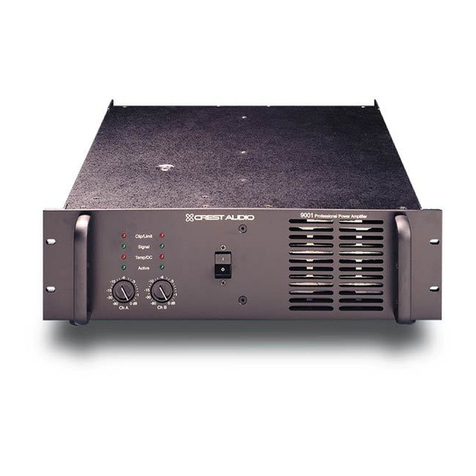
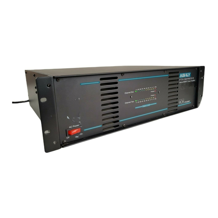
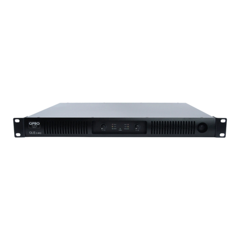
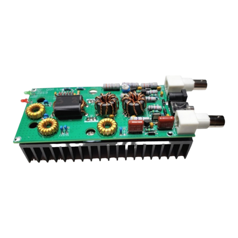
Electro-Metrics PA-1000 User manual

INSTRUCTION MANUAL
BROADBAND
POWER AMPLIFIER
MODEL PA-1000
10 MHz –1 GHz

INSTRUCTION MANUAL
THIS INSTRUCTION MANUAL AND ITS
ASSOCIATED INFORMATION IS
PROPRIETARY. UNAUTHORIZED
REPRODUCTION IS FORBIDDEN.
1995ELECTRO-METRICS CORP.
BROADBAND POWER AMPLIFIER
ELECTRO-METRICS
MODEL PA-1000
10 MHz-1 GHz
SERIAL NO: N/A
ELECTRO-METRICS CORPORATION
231 Enterprise Road, Johnstown, New York 12095
Phone: (518) 762-2600 Fax: (518) 762-2812
MANUAL REV. NO: PA1000-0395 ISSUE DATE: MARCH 01 1995

ELECTRO-METRICS AIT-SUS
WARRANTY
This Model PA-1000 Broadband Preamplifier is warranted for a
period of 12 months (USA only) from date of shipment against
defective materials and workmanship. This warranty is limited to
the repair of or replacement of defective parts and is void if
unauthorized repair or modification is attempted. Repairs for
damage due to misuse or abnormal operating conditions will be
performed at the factory and will be billed at our commercial
hourly rates. Our estimate will be provided before the work is
started.

ELECTRO-METRICS PA-1000
(PA-A-1)
APPENDIX A
PA-1000 ACCESSORIES
A-1.0 Standard Accessories
The following accessories are included as standard with each PA-1000.
a. Power Cord.

ELECTRO-METRICS PA-1000 BB POWER AMPLIFUER
(PA1000-
1
)
DESCRIPTION AND USE ELECTRO-METRICS
MODEL PA-1000 BROADBAND POWER AMPLIFIER
1.0 Introduction
The Electro-Metrics Model PA-1000 Broadband Power Amplifier is a general purpose
signal amplifier that can be used in susceptibility tests, shielding effectiveness tests, insertion
loss measurements, plus numerous other applications where signal amplification is required.
2.0 Specifications
2.1 Electrical
Frequency Range: 10-1000 MHz.
Gain: 16 dB, minimum.
(Gain level chart furnished with each unit.)
Flatness: ±1.0 dB.
Maximum Safe Input Level: 100 mW (2.2 Vrms).
Power Output: +29 dBm.
Impedance: 50.
VSWR: <2:1.
Connectors: Type BNC.
Power: 115/230 VAC, 50-60 (17 W).
2.2 Mechanical
Length: 300 mm (11.9").
Width: 224 mm (8.8").
Height: 148 mm (5.8").
Weight: 3.6 kg (8 lbs).

ELECTRO-METRICS PA-1000 BB POWER AMPLIFUER
(PA1000-
2
)
3.0 Power Supply
3.1 Power Requirements
a. AC power sources:
1) 105-130 VAC, 50-60 Hz.
2) 210-260 VAC, 50-60 Hz.
3.2 Power Source Selector
The Power Source Selector is incorporated as part of the power input connector. The
number visible in the window indicates the nominal AC power source for which the receiver is
set. To change the power source setting:
a. Remove the power cord from the connector plug.
b. Slide the clear cover to the left.
c. Pull the handle marked FUSE PULL and remove the fuse.
d. Rotate the handle to the left and gently pull the printed circuit voltage selector
card from its slot.
e. Orient the card so that the desired operating voltage appears on the top-left side.
f. Firmly push the voltage selector card back into its slot.
g. Rotate the FUSE PULL handle to the right and install the correct rating fuse.
h. Slide the clear cover to the right and reconnect the AC power cord to the
connector.
CAUTION
Verify that the Power Source Selector setting corresponds to
the AC power source being used. Operation on "220" VAC
with the module set for "110" VAC can cause extensive circuit
damage.
3.3 Fuse Specifications
The PA-1000 uses the following fuses:
a. 115 VAC operation: 1.0 AMP 3AG SLO-BLO.

ELECTRO-METRICS PA-1000 BB POWER AMPLIFUER
(PA1000-
3
)
b. 230 VAC operation: 0.5 AMP 3AG SLO-BLO.
4.0 Description Front/Rear Panel
4.1 Front Panel
a. POWER ON INDICATOR
Type: LED.
Color: Amber.
Function: when lighted, indicates that the PA-1000 is turned "ON".
b. POWER SWITCH
Type: Two position toggle switch.
Function: Used to place the unit in operation.
c. INPUT/OUTPUT CONNECTORS
Type: BNC.
Quantity: Two (2).
Function: Self-explanatory.
4.2 Rear Panel
a. POWER INPUT CONNECTOR
Type: Combined voltage selector and fuse holder.
Function: Connects the PA-1000 to the selected AC power source.
5.0 Operating Instructions
5.1 Initial Power Up Procedure
a. Before applying power to the PA-1000 check the following:
1) Power Source Selector setting should correspond to the AC power source being
used.
2) FUSE should be correct rating for the AC power source being used.

ELECTRO-METRICS PA-1000 BB POWER AMPLIFUER
(PA1000-
4
)
b. Connect the power cord between the rear panel POWER Connector and the AC
power source. The PA-1000 is turned on using the front panel POWER Switch.
The LED "POWER-ON" indicator should be activated whenever the unit is on.
Allow a minimum warm-up time of 30 minutes.
5.2 Applications
The PA-1000 Broadband Power Amplifier is designed to be used whenever signal
amplification is required within a test system.
CAUTION
The minimum gain of 16 dB, from 10 MHz to 1 GHz, is for a
50-ohm impedance and the maximum safe input level is 2.2
Vrms. If the 2.2 Vrms input level limit is exceeded, the internal
circuitry of the unit may be damaged.
For susceptibility testing, the PA-1000 can be used for both conducted and radiated tests.
In performing MIL-STD-461B conducted susceptibility tests using Method CEO2, the PA-1000
will provide the 1 Volt or 1 Watt test signal that is required from 10 to 400 MHz. In performing
MIL-STD-461B radiated susceptibility tests using Method RS03, the PA-1000 will drive a half-
meter or smaller TEM cell to over 10 V/m and the Electro-Metrics Model RGA-30 antenna to
over 5 V/m.
In shielding effectiveness tests, it used with the ASTM Near Field Test Fixture for
improving the dynamic range of the test. When used with the ASTM Far Field Test Fixture, it
improves the signal to noise ratio. These tests are further defined by the American Society for
Testing Materials (ASTM) emergency standard ES 7-83. The use of the PA-1000 in the Electro-
Metrics ASTM Shielding Effectiveness Test Systems is discussed in the manuals for the
respective systems.
The PA-1000 may also be used to drive antennas in performing MIL-STD-285 and IEEE-
299 shielding effectiveness tests of shielded rooms and enclosures. However, depending on the
capability of the receiving equipment used in these tests, certain high-performance shielding
enclosures may require a significantly higher power output.
If the PA-1000 is being used as an antenna output amplifier, there is the possibility of
damage being caused by electrostatic discharges (ESD). This situation may occur since most
antennas have a center conductor with a shield ground and not an actual earth ground. Under
certain enviromental conditions (low humidity, low temperatures, etc), static built-ups may
occur. If discharged through the PA-1000, it could cause damage to the amplifier circuitry. Use
proper grounding techiques within the test setup to minimize this problem.
Insertion loss measurements often require moderate to low power sources for testing
filters and other networks. In combination with the Electro-Metrics Model EMC-30 and a
standard laboratory signal generator, the PA-1000 will provide an insertion loss measurement
range from 160 dB at 10 MHz to 140 dB at 1 GHz.

ELECTRO-METRICS PA-1000 BB POWER AMPLIFUER
(PA1000-
5
)
The PA-1000 can also be used as a post-amplifier in combination with the BPA-1000
Broadband Amplifier for special broadband, high dynamic range measurements. The two units
combined provide a third-order spurious free dynamic range (SFDR) of 47 dB (Bandwidth: >990
MHz, Overall Noise Figure: 6.0 dB, Gain: 43 dB). This provides an impulse sensitivity of -31
dB(µV/MHz) for the 990 MHz bandwidth.

ELECTRO-METRICS PA-1000 BB POWER AMPLIFUER
(PA1000-
6
)
FIGURE 1
GAIN LEVEL CHART
PAGE 6A
Table of contents
