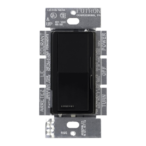
Electro-Sensors LRB1000 User manual

Principles of Operation
The LRB Series Switch is supplied with a shaft mounted magnetic disc
or wrap which generates an alternating magnetic eld that is picked
up by the non-contact sensor. The sensor transmits this speed signal
as a digital pulse (frequency) to the switch via a 3-conductor shielded
cable. The LRB Switch decodes this frequency signal to determine shaft
speed, and compares this to its adjusted set point(s). This comparison in
conjunction with the choice of under speed or over speed mode, allows
the relay output to be used for alarm and/or shutdown, assuring optimum
machine protection and process integrity. A feature of the LRB-Series
Switch is the ability to mount the switch on a DIN rail. This is useful
for installation where plant electrical controls are centrally located
in a control cabinet. Consult Electro-Sensors, Inc. for information on
enclosures if needed.
The LRB-Series Switch System includes the terminal block mounted
switch, a non-contact Hall-Effect sensor and a magnetic disc or optional
pulser wrap. The Model 906 sensor is designed for standard service. An
optional explosion proof sensor Model 907 is available for hazardous
locations. The sensor is connected to the terminal block on the LRB
Series Switch (gure 3).
Start Delay
A 10-second Start Delay is built into the LRB Series Switches. In Under
Speed Mode, the Start Delay holds the relay(s) in an energized state for
10 seconds, allowing the monitored shaft to reach a speed above the set
points(s) before monitoring begins. The Start Delay begins when power
is applied to the LRB Series Switch.
Signal Loss Protection
In Under Speed Mode, a loss of the sensor signal will be detected
immediately, and the relay will de-energize. In Over Speed Mode,
the loss of signal is detected and the LRB Series Switch will wait
30-seconds for the signal to resume, preventing unwanted signal loss
shutdown when monitoring a very slow speed shaft. After the 30-second
interval has elapsed with no incoming signal, the relay is de-energized.
Special Options
Special options are available from the factory to modify the standard
functions of the LRB Series Switches. Options include:
Increased, decreased or zero start delay; increased or decreased setpoint
hysteresis; extended ranges; and signal loss protection deactivation in
over speed mode.
Pulser Disc
To mount the Pulser Disc, center drill the monitored shaft to a depth of
1/2 inch with a No. 21 drill and tap it for a 10-32 UNF screw. Apply
Loctite™ or a similar adhesive on the screw threads to keep the pulser
disc tight. Attach the disc, decal side out, with the 10-32 UNF machine
screw provided. Pulser Discs can be used with all Electro-Sensors, Inc.
sensors.
Pulser Wrap (optional)
Pulser wraps are custom manufactured to t the specic diameter of the
shaft on which they will be mounted. To mount the wrap, remove the 4
Allen-head cap screws holding the halves of the wrap together, place the
halves around the shaft, and reinsert the screws. Tighten the screws to 5
ft. lbs. Pulser Wraps can be used with all Electro-Sensors, Inc. sensors.
Sensor Installation
The standard sensor is supplied with a mounting bracket and two jam
nuts. The explosion proof sensor is supplied with a slotted mounting
bracket. Sensors should be installed so the center line of the magnets
pass in front of the center of the sensor as the disc or wrap rotates. When
using the pulser disc, the center of the magnetized area of the disc,
shown as Dimension B in gures 1 and 4, is 1-3/4 inches from the center
hole of the disc. The recommended gap distance between the sensor and
the disc or wrap, Dimension A in the diagrams, is 1/4-inch ± 1/8 inch. To
achieve the proper gap distance, adjust the jam nuts holding the standard
sensor in the mounting bracket, or adjust the position of the explosion
proof sensor using the slots on its mounting bracket.
Figure 1: Standard 906 Sensor and Pulser Disc
�
�
Figure 2: Standard 906 Sensor and Pulser Wrap
LRB1000 / LRB2000
DIN Rail Mount Speed Switch
6111 Blue Circle Drive
Minnetonka, MN 55343
Phone: 952.930.0100
Fax: 952.930.0130
ISO 9001:2000 Certied
Free Catalog and Application Assistance
1.800.328.6170
Visit Us Online
www.electro-sensors.com
990-001300 Revision E

Figure 4: Explosion proof 907 Sensor and Pulser Disc
�
�
Figure 5: Explosion proof 907 Sensor and Pulser Wrap
Sensor Connection Table
Terminal Sensor model
906/907
Other ESI
Sensors
Type NPN
ESI Prox
Type NPN
5 Supply Red Red Brown
6 Signal Black White Black
7 Common White/Shield Black/Shield Blue
Power Input Table
Terminal 12 & 24 VDC 115 VAC 230 VAC
2 (+) Positive Hot Hot (L1)
10 (-) Negative Neutral Hot (L2)
Relay Connections
Terminal Setpoint 1 Terminal Setpoint 2
1 Common 11 Common
3 N.O. 9 N.O.
4 N.C. 8 N.C.
LRB 1000/2000 LRB 2000 ONLY
Figure 3: Base Wiring Diagram
Switch 1 Set Point
ON 1 - 100 RPM
OFF 10 - 1000 RPM
Switch 2 Mode
ON Underspeed
OFF Overspeed
Figure 6: Setpoint Setup
There are 3 steps to calibrating the LRB 1000/2000
1. Determine whether the relay should de-energize when the shaft
speed drops below the set point speed (Under Speed Operation,) or
when the shaft speed goes above the set point speed (Over Speed
Operation.) Use the Over/Under Speed Selection Switch to place the
LRB 1000 in the desired mode (see Figure 6, for switch position.)
2. If the set point will be set to trip the relay at a speed below 100 rpm,
set the Set Point Range Selection Switch to the 1-100 rpm range. If
the set point will be set to trip the relay at a speed that is above 100
rpm and below 1000 rpm, select the 10-1000 rpm range
3. Set the Rotary Set Point Switches to the desired set point speed. The
switches can be set at any number from 01 to 99.
For example:
If the RPM Range Selection Switch is set in the 1—100 rpm Range and
the desired set point speed is 50 rpm, the Set Point Switches should be
set to 50. In the 10 to 1000 rpm range, the set point is 10 times the switch
setting (i.e. a switch setting of 80 results in a set point of 800 rpm.)
NOTE: Calibration should be done with power to the LRB 1000 turned
OFF. If a change is made to the calibration while power is ON (Not
Recommended,) cycle power to the unit. This will store the new set point.
The standard pulser disc or wrap will produce 8 PPR.
2-4
Free Catalog and Application Assistance
1.800.328.6170
Website: www.electro-sensors.com
990-001300 Revision E

Figure 7: Typical Wiring Diagram
This Wiring Conguration Will Disable the Alarm on a Stop
Command. To Maintain the Alarm, Replace the Maintained Stop
Switch with a Momentary Normally Closed Switch
WARNING!
During a stopped condition, even a slight movement of the shaft
magnet disc could energize the control relay and start the motor if
the Motor Starter Auxiliary Normally Open Contact (MS Aux N.O.) is
not wired in series as shown in these typical wiring diagrams. This
situation could cause equipment damage or PERSONAL INJURY!
To prevent starting the motor accidentally, ALWAYS USE PROPER
LOCK-OUT/TAG-OUT PROCEDURES.
LRB 1000/2000 Dimensions:
LRB1000/2000
Terminal Block
Pulser Disc
Nut &
Lockwasher
Explosion proof 907 Sensor
Explosion proof 907 SensorBracket
Standard 906 Sensor
3-4
Free Catalog and Application Assistance
1.800.328.6170
Website: www.electro-sensors.com
990-001300 Revision E

Troubleshooting Guide
Problem
Relay will not Energize, LED does not “Light Up”
Possible Solutions
AC power is not applied to the
LRB terminal block correctly.
Check input power connection
table
Sensing head is not aligned or
gapped properly.
See pages 1 & 2. Figures 1,
2, 3, 4
The set point is not in the
proper range. See page 2, Figure 5
Shaft is not turning faster than the
set point. Check actual RPM.
Sensing head is not wired
correctly to the LRB Speed Switch.
Check Sensor Connection
table on page 2 for correct
wiring
Sensor Supply Voltage is not
present.
Check for approx. 12 VDC
between TB5 & TB7
LRB Speed Switch is not
receiving signal.
Check for approx. 2.5 VDC
between TB6 & TB7 with
shaft running
LRB 1000/2000 Specications:
Input Voltage ±10% Input Current Fuse Type
LRB1000/2000 (with standard ESI sensors)
115 & 230 Vac, 60 Hz 2.5 vA 0.032A Slo-Blo 5X20
LRB1000 (with standard ESI sensors)
12 & 24 Vdc 45 mA 80 mA Slo-Blo 5X20
LRB2000 (with standard ESI sensors)
12 & 24 Vdc 75 mA 125 mA Slo-Blo 5X20
Input Signal Parameters
Type Open Collector/Logic
Amplitude 5V Pull-Up
Pullup 2200 Ohms to 5V
Max Frequency Input 500Hz **
Min. Pulse Width 1 mSec
Set Point Data Parameters
Number of Set Points One or Two
Actuation State Under or Over Speed
Set Point RPM Range 1 - 99 RPM
10 - 990 RPM **
Adjustment Rotary Switches:
1 (10x)
1 (1x)
Set Point Accuracy 0.005% @ Low range
0.25% @ Mid Range
0.5% @ Top Range
Hysteresis 6.6% **
Contact Arrangement:
LRB 1000:
LRB 2000:
One Form C, SPDT
Two Form C, SPDT
Relay Contact Rating 5 Amp @ 30 Vdc, or 250 Vac
resistive
Start Delay 10 Seconds (Fixed) **
Physical/Enviroment Parameters
Electrical Connection 11 - Position DIN Rail Terminal
Block
Operating Temperature -40°C to +60°C
Storage Temperature -65°C to +125C
Mounting DIN Rail Mount or Stand Alone
Enclosure Rating NEMA 1
UL508 Approved UL File# E254289
906 Sensor Parameters
Body Material Aluminium
Bracket Material Steel
Thread Size 3/4 - 16 UNF
Output Type Open Collector, Current Sinking
20 Ma Max
Signal Cable 3 - Conductor Shielded 10 ft.
supplied std.
Max Cable Length 1500 Ft.
Operating Temperature -40°C to +60°C
Air Gap 1/4 in. +/- 1/8 in.
907 Explosionproof
Sensor (optional)
Parameters **
Class I, Div 1, Group D
Class II, Div 1, Groups E, F, G
UL File: E249019
Mounting Bracket Material Plate Steel U-Bolt Assembly
Other Specications Similar to 906 standard sensor
Pulser Disc Parameters
Material Nylon 12 Std.
Aluminum Optional
Operating Temperature -40°C to +60°C
Maximum Speed Consult Factory
Pulser Wrap Parameters
Material Consult Factory
Operating Temperature -40°C to +60°C
Maximum Speed Consult Factory
Specications are subject to change without notice.
*For higher temperature ranges, consult factory.
** Other settings available, consult factory.
4-4
Free Catalog and Application Assistance
1.800.328.6170
Website: www.electro-sensors.com
990-001300 Revision E
This manual suits for next models
1
Table of contents


