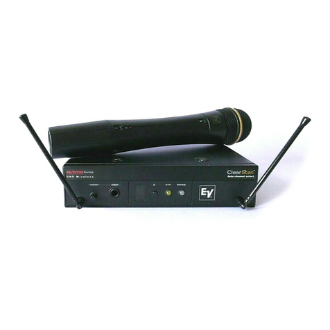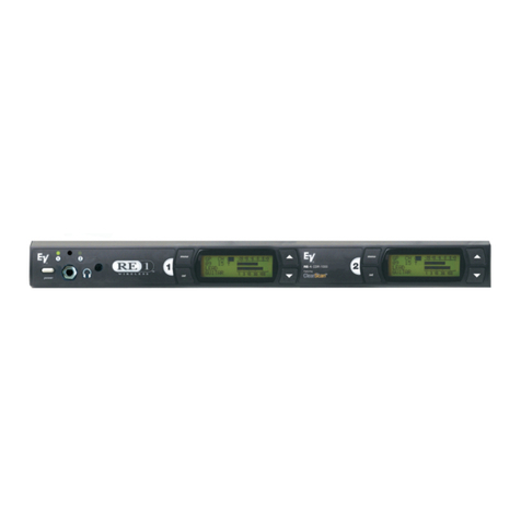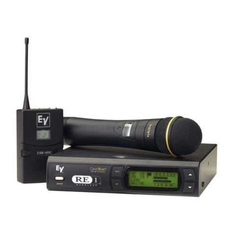
3.1 Receiver Setup and Operation
A. Receiver Setup
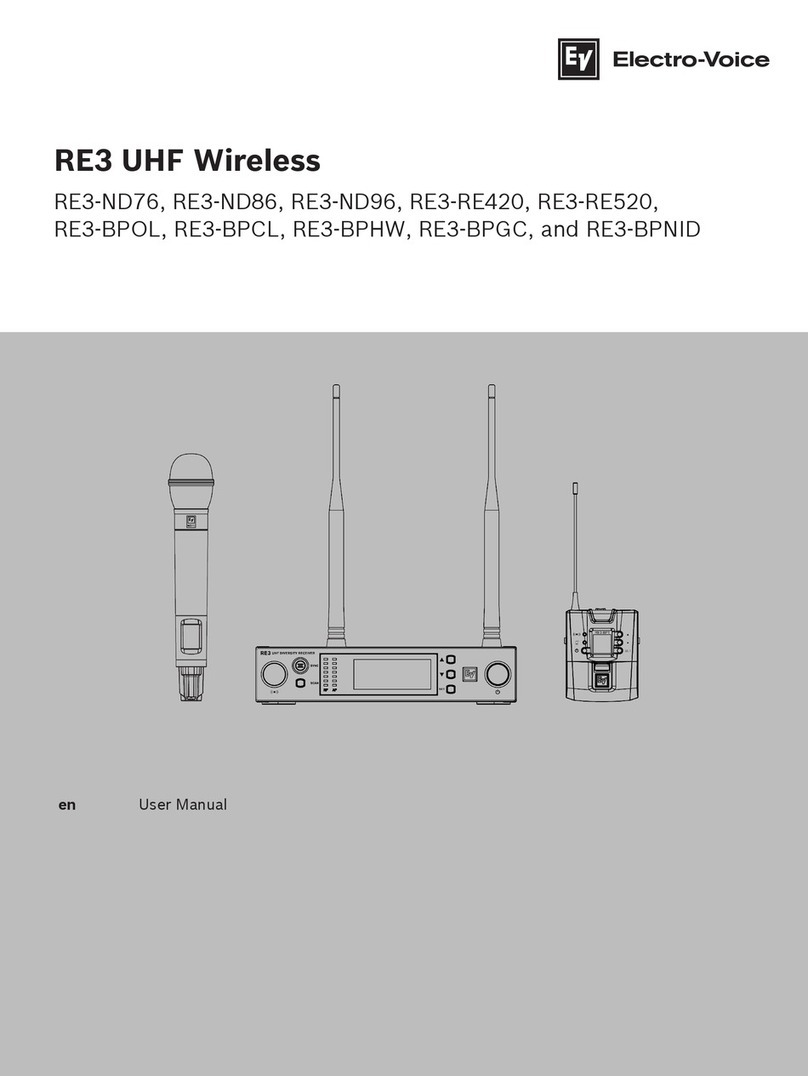
1.Place the receiver and antennas where there is a clear
line of sight to the area where the transmitter will be
used. Rotate the antennas to separate them by 90 de--
grees. See Part 15 for more information.
2. Connect the power cord to the receiver. Turn the re--
ceiver on and confirm that it is ON by checking the
main display screen. The display will show the com--
pany logo, software revision level and then display
the main screen with the last channel set.
B. Manual Channel Change
1. From the main display screen press the MENU but--
ton once to display the edit screen.
2. Press SET and the group number will flash. The UP
and DOWN buttons allow you to scroll through the
18 factory groups and 2 user definable groups.
3. When the group you desire is displayed, press SET
to select that group and the Channel Number will
start flashing.
4. Scroll to the desired channel, press SET to select.
5. Pressing MENU anytime before pressing SET ne--
gates any changes made since the last SET.
6. Once the desired group and channel are displayed
(but not flashing) press MENU twice to return to the
main display screen.
C. Frequency Assignment (User Defined Groups Only)
1. With a User Group (19u or 20u) and channel se--
lected in step three, press SET until the Frequency
Number flashes.
2. Use UP/DOWN to scroll in 25 kHz steps to the de--
sired frequency. With the desired frequency dis--
played press SET. Hint: holding in the arrow key will
increase the speed of the scroll. Just release and
press again for fine control.
3. Repeat until all desired Channels in the user group
are assigned a frequency.
4. Press MENU twice to return to the main display
screen.
D. Advanced ClearScan: This feature automates the pro--
cess of finding a clear group of inter-modulation free
channels and the clearest channels within those
groups. From the main display screen push Menu twice
to go to the MENU Screen and press SET to select
ClearScan.
E. ClearScan
All: This function scans all of the groups (fac--
tory and user) and returns a list of groups ranked by the
number of free channels.
1. Once ClearScan All has run, the screen will display
the clearest group with the open channels in that
group. You can scroll through the other ranked groups
using UP/DOWN.
2. When you have the group you want, press SET to run
ClearScan on that group. The display will now show
the group with the Channels ranked by clearness and
the clearest channel will be flashing.
3. Press SET to select and the clearest channel will be
installed, display will return to the main display.
NOTE:
Groups 17 and 18 have 16 channels and are marked
with an N (17n). These groups require the transmitters
to be in the LOW transmit power setting to work to--
gether. After ClearScan All runs, the N groups will al--
ways be displayed after groups 1-18 and any user
defined groups no matter how many channels are
free. If you need to use more than 12 systems at one
time, scroll down to the N groups and use the clearest
group with Normal transmit power.
F. ClearScan Group: this function will scan the group cur--
rently selected, which is useful for multi-system setup.
1. Use ClearScan All on the first unit of a multi-system
installation to select the clearest group.
2. For each system added, leave all previously selected
channel transmitters on, using Step 3 select the cur--
rent group, select ClearScan Group and press SET.
3. The display will show the remaining clear channels in
the group with the clearest flashing.
4. Select the desired channel with UP/DOWN or simply
press SET for the clearest channel.
5. The channel will be selected and return to the main display.
6. Repeat until all systems are set up.
G. ClearScan Band: selects and ranks the clearest 16 fre--
quencies in the 24 MHz bandwidth regardless of groups,
channels or previous coordination. This feature is useful for
selecting one clear channel in a very busy RF environment.
1. From the Options screen, select ClearScan Band and
press SET.
2. This scan will run until SET is pressed again so it can be
used to evaluate a site over an hour, day or even a week.
3. To end scan, press SET, the program displays Group
21S with the clearest open frequencies in the band as--
signed channels (up to 16).
4. These frequencies will remain assigned to this group
until ClearScan Band is run again.
Caution: Unlike the factory assigned groups, the channels in
21S are not coordinated. If more than two channels from
group 21S are used, the combination must be walk tested
with all transmitters on before use.
-4-
