2
3. Specications
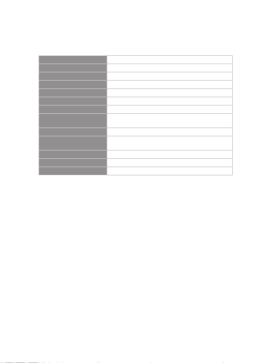
3-1 UHF PLL single/dual-channel diversity receiver
Model
Frequency Oscillation
Mode
Phase-locked loop (PLL)
Carrier Frequency Range 470~960 MHz
Remoset Frequency Ultrasonic
Diversity Antenna diversity
Bandwidth 36MHz
Signal/Noise Ratio >105dB(A)
Total Harmonic Distortion
(Thd)
<0.6%@1KHz
Receiving Sensitivity -95dBm,S/N>80dB
Image Rejection Ratio >80 dB
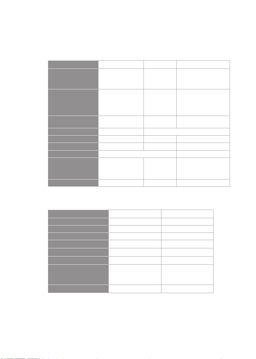
Frequency Response 60Hz~15KHz±2dB 50Hz~16KHz±2dB
Antenna Type 1/4λ Fixed antenna 1/2λ BNC detachable
Antenna Booster Power None DC12~15V/100mA
Function Display By LCD
Contents Of Display
Group, channel, antenna
A/B, muting level, AF
indication, RF indication,
channel scanning, output
level attenuation, volume
indication
Group, channel, frequency, battery
level, antenna A/B, muting level, AF
indication, RF indication, channel
scanning, output level attenuation,
volume indication
Control Functions
Power, group, channel,
muting level, channel
scan (on/o), button lock,
volume, output attenuation
(XLR)
Power, group, channel, frequency,
muting level, button lock, volume,
output attenuation (XLR), channel
scan (on/o)
Audio Frequency Output
Level
Ref:±22.5KHz Dev@1KHz Tone
ψ6.3 Phone Jack:-10dBV
XLR Jack:-4dBV(Line)、-24dBV(MIC)
Audio Frequency Output
Impedance
600Ω