manuals.online logo
Brands
  1. Home
  2. •
  3. Brands
  4. •
  5. Electro-Voice
  6. •
  7. Microphone System
  8. •
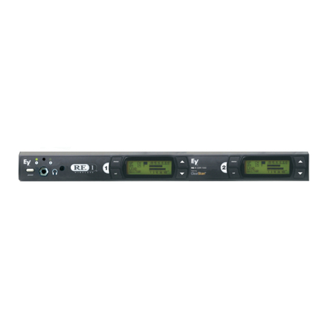
  9. Electro-Voice Telex RE-1 User manual

Electro-Voice Telex RE-1 User manual

PROFESSIONAL
MICROPHONE
SYSTEM
The loudspeaker arrays have gone up. The stage design is
finished. The pyrotechnics have been coordinated. The front-
of-house engineer has everything tweaked to his liking. Yet, he
takes the time to test and retest the wireless several times. Why?
Because like most engineers worth their weight, this guy knows
that poor wireless can ruin a show. t is absolutely essential that
everything work 100% — with no drop-outs or interference —
all systems go, without-a-hitch.
Where does the engineer turn to minimize the stress of his job?
To Electro-Voice®, a company that has over 25 years of experience
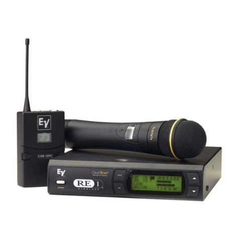
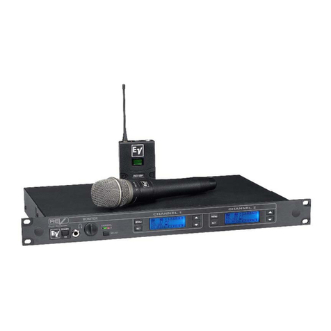
in wireless innovations. The RE-1™Wireless system takes frequency
agility to a whole new level... touring market power with unmatched
simplicity. The clear channels have always been there — but it took
EV to bring them to your fingertips. Now you can feel secure that
even the most crowded RF environments — places like New York City
or the San Francisco Bay area — are fully manageable with the
Electro-Voice RE-1!
So, when the demands of high-energy, real-world touring present
themselves, be prepared... whether the show is in Yankton, South
Dakota or Dallas, Texas, performers have to sound their very
best. Wired or wireless, professional sound engineers will tell
you that there is absolutely no room for mistakes in the
production of upscale performances. Bottom line: When only
the very best in wireless technologies will do, step up to the
Electro-Voice RE-1™Wireless...
PROFESSIONAL MICROPHONE SYSTEM
Transmitter Features
• Unique “smart” battery circuit in the
transmitters means there is no way
to put the battery in wrong.
• LCD display and the same four control
buttons as the receiver so programming
a channel or frequency is quick and easy.
• Low battery LED will light when the
battery needs a replacement.
• One on/off switch that also acts
as a mute, great for pauses in
presentations and worship services.
• On/off button can be disabled to
prevent accidental turnoffs
during a performance.
• Normal and High power trans-
mit means you use just enough
power for the application, which maxi-
mizes the number of simultaneous sys-
tems and limits RF spill over into adjacent
buildings/theaters.
Handheld Features
•Interchangeable microphone head allows
a choice of elements to fit the vocalist’s
style and environment.
•N/DYM®767a premium dynamic vocal
microphone with VOB™(Vocal-Optimized
Bass), excellent gain-before-feedback for
high SPL stages.
•The new RE-510 premium condenser
vocal microphone for experienced vocalists,
spoken word and quieter stages.
•Internal 1/2-wave antenna for excellent
range; stays out of harm’s way.
•An over-molded Warm-Grip™handle
reduces handling noise and encourages
proper microphone technique for
better performances.
RECEIVER FEATURES AND BENEFITS
•Optimized channel groups allow up to 16 systems to operate simultaneously in one
frequency band. For groups larger than 16, EV can help with the coordination and
custom groups are easily programmed.
•Programmable in 25 kHz steps across 24 MHz operating bandwidth, there
are over 950 possible channels so you can always find a clear channel.
•Advanced ClearScan™
, automatic group and channel selections, allows quick,
simple setup.
•Backlit LCD Display shows the Sound Engineer the Group/Channel, transmitter battery
status, diversity operation, RF and Audio level meters, and space for
a custom name (2 lines, 10 characters each).
•Specially designed “Sound Check”mode provides the ability for
one person to walk test the microphone in the performance space
with tangible results.
•Patented DSP Posi-Phase™Diversity System for maximum range and audio quality.
•Balanced XLR microphone output and 1/4-inch unbalanced adjustable line-level
output to match the application.
•CDR-1000 Dual Receiver includes internal power supply, headphone monitoring jack,
balanced line-level output, antenna pass through, DC power on antenna jacks for optional
RF amplifier, and RE-OneLink™PC software for remote monitoring and control.
•Rackmount hardware included.
•Three-Year Limited Warranty.
TRANSMITTER FEATURES AND BENEFITS
Bodypack Features
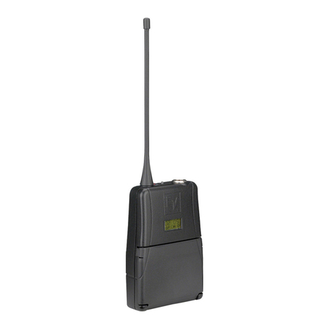
•Cast magnesium housing weighs only ounces but
is durable enough to take the pounding on tour.
•Detachable 1/4-wave antenna allows for easy
replacement or the use of different antenna options.
•Cell phone style beltclip included for quick and
easy attachment. Optional pouches also available
for wearing under costumes or for more
vigorous applications.
•EV has a wide selection of lapel and headworn
microphones and microphone accessories to go
with the RE-1 bodypack transmitter.
Unique Bodypack Features for Guitar Applications
•Dual band compander circuit provides the audio
bandwidth required to cover the lows of a bass
guitar to the highs of a solid body.
•Mic/Instrument switch adds a 20 dB pad in the
transmit path so the standard bodypack can be used
for microphone and guitars.
•Guitar patch cord featuring George L’s®cable with
solderless, interchangeable right angle and straight plugs
included to fit your guitar.
APD-4 ANTENNA DISTRIBUTION SYSTEM
•Drives up to four CSR-1000 diversity receivers using a
single pair of antennas to conserve rack space and eliminate
the “antenna farm”.(8 TNC output and 2 front-mount antenna
cables included, 1/2-wave antennas sold separately.)
•Drive 24 receivers from one APD-4 and 2 antennas
using the antenna pass through splitter included on
every CDR-1000 Dual Receiver.
•Supports “cascade”arrangement of multiple APD-4
splitters to drive up to 16 CSR-1000 receivers using just
2 antennas.
•Power outputs for up to four CSR-1000 receivers help
conserve power strip space (4 cables included).
Advanced ClearScan™
Frequency agile wireless microphones solve many problems with
interference and compatibility. They also create a problem, how
do you know which channel is best to use in your application?
Advanced ClearScan scans the energy on each channel, and it
selects the clearest preset groups of up to 16 compatible
channels and the clearest channels within the clearest group.
Without a separate computer, difficult software, or an RF
consultant… with the touch of a couple of buttons and a few
seconds, Advanced ClearScan gives you the confidence of
knowing you have clear, compatible channels.
THE MENU KEY SELECTS THE CLEARSCAN MENU
PRESSING THE SET KEY STARTS THE SCANNING PROCESS
THE CLEAREST GROUP AND OPEN CHANNELS WITHIN THAT
GROUP ARE DISPLAYED.
PRESSING THE SET KEY ACCEPTS THE GROUP, RUNS CLEARSCAN
GROUP AND DISPLAYS THE OPEN CHANNELS IN ORDER OF CLEARNESS.
PRESSING THE SET KEY ACCEPTS THE CHANNEL, INSTALLS THE
GROUP AND CHANNEL AND RETURNS TO THE MAIN SCREEN.
ADVANCED
ADVANCED CLEARSCAN
™
INCLUDES THREE OPTIONS:
ClearScan™All
• Scans all 10 factory preset groups and any user-defined
groups that have channels assigned in them.
• The scan produces a list of open groups and channels
in order of maximum number of open channels.
• The results are displayed as the group number and the
open channels within that group starting with the most
open group. The Arrow keys allow you to step through
the other groups so you can see all of your options.
• Once you have selected the group you like, pressing
SET with that group showing starts the ClearScan
Group function.
ClearScan™Group
•Scans all of the channels in the currently selected group.
•The results are displayed in a screen that shows the
group number and all of the open channels listed in
the order of clearness.
•The Arrow keys allow you to scroll through the channels
to highlight the channel you want to install.
•Pressing the SET key installs the highlighted
group/channel and returns to the main operating screen.
•Set the transmitter group and channel to match and
set up is complete.
ClearScan™Band
•This unique feature scans the entire 24 MHz operating
band looking for clear frequencies, regardless of channels
and groups.
•This function can be used to find one clear frequency in
a very tough RF environment or find starting points for
custom channel programming.
•Since the frequencies returned from the ClearScan Band
function have not been screened for inter-modulation
problems, walk testing or coordination help from EV
would be required before multiple channels from
ClearScan Band results could be used at the same time.
Multiple System Setup with Advanced ClearScan™
•Because the factory preset groups are made up of
compatible channels, setting up to 8, 10 or even 16 systems
is a snap. Just run ClearScan All once to select a group
with enough free channels for all of your systems.
•Once the first system is set up, you simply leave that
transmitter on and run ClearScan Band on the next
receiver. The next clearest channel is then set on system
number two, leave that transmitter on and repeat until
all of the systems have channels assigned.
RE-1 Accessories and Parts
Model # Order #
Omnidirectional MicroMini™ Lapel Mic: RE90TX 71753318
Unidirectional MicroMini™Lapel Mic: ELM-33S 70926001
Crown®CM-311 Headworn Uni Mic: HM311 HM311
Headworn Cardiod Condenser Mic: HM7 HM7
1/4 Wave Rx Antenna 600-746 (A/B): ANU-14 879010
1/2 Wave Rx Antenna (A and B) (680-860 MHz):FA-1 860031
1/2 Wave Antenna Bracket: AB-2 71138000
UHF Antenna Amplifier (520 - 806 MHz):UAA-500 7186400
Antenna /Pwr Distribution (A/B) (600-780 MHz):APD- 4 APD4
Termination Plug For APD-4: TP-2 650095
Directional Rx Antenna (450-900 MHz):LPA-500 LPA500
Low Loss Coaxial Antenna Cable: CXU-25 ft 71151025
CXU-50 ft 71151050
CXU-75 ft 71151075
CXU-100 ft 71151100
1/4 Wave Bodypack Tx Antenna (A): AN-Flex A (GREEN) 879220-4
1/4 Wave Bodypack Tx Antenna (B): AN-Flex B (RED) 879220-5
1/4 Wave Super-Flex Tx Antenna (A): AN-Sflex A (GREEN) 879538-4
1/4 Wave Super-Flex Tx Antenna (B): AN-Sflex B (RED) 879538-5
Bodypack Pouch: WP-1000 879553
Guitar Cord: MAC-G2 879526
767a Dynamic Head for CSH-1000: RC767A 71837000
RE510 Condenser Head for CSH-1000: RC510 71839000
Mic Stand Adapter for CSH-1000: MSA-1000 879564
Front Panel Top
Under
Battery
Cover
CSB-1000 Bodypack Transmitter
CSH-1000 Handheld Transmitter
Panel Front
Back Gain
CDR-1000 Receiver
PA 20599-1 09/02 ZM©2002 Telex Communications, Inc.
12000 Portla d Ave ue South
Bur sville, Mi esota 55337
1-800-392-3497
www.electrovoice.com
STEP UPTOELECTRO-VOICE®
CSR-1000 Receiver
Front
Back
Front
Back
CSR-1000 Receiver
Controls
Front Panel: On/Off, Menu, Set, Up, Down Buttons
Rear Panel: 1/4 in. output level
Indicators LCD Group, Channel, Diversity, Label, Set-up
Backlit Display: Transmitter Battery Level, Audio Signal
Amplitude and RF Signal Strength, Squelch
Connectors
Back Panel: 1/4 in. unbalanced adjustable line level output
XLR balanced mic level output
USB programming port
Antennas: Detachable 1/4 wave
RF Specifications A Band 680 –704 MHz (TV Channels 49-52)
Frequency Range: B Band 722 –746 MHz (TV Channels 56-59)
Number of Channels: 950 possible (programmable in 25kHz steps)
Diversity: DSP SecurePhase True Diversity
Squelch: Tone Code plus Adjustable Amplitude
Receiver Type: Synthesized PLL Agile UHF
RF Sensitivity: <0.8uV for 12 dB SINAD
FCC Type Acceptance: Approved under Part 15
Audio Specifications 100 –15 kHz +/- 2 dB Microphone
Frequency Response: 30 –15 kHz +/- 2 dB Instrument
Audio Output Level:
Line Level 8 mV - 0.775V RMS @ 100 k ohm load
Balanced -10 dBV max (@ 40kHz deviation)
Distortion: Less that 0.5% (@ 1kHz, 40 kHz deviation)
Signal to Noise Ratio: > 110 dB (A)
Dynamic Range: >100 dB
General Specifications
Power Supply: External 12 VAC 750mA in-line with cord
Size: 1.72 in. H x 7.50 in. W x 8.38 in. D
43.69 mm H x 190.50 mm W x 212.85 mm D
CDR-1000 Features
Additional Audio Output: Adjustable Balance Line Level at XLR
Additional Controls: 1/4 in. Headset Jack with Selector and Volume Control
Antenna Output: TNC
Powerered Antenna Inputs: 12Vdc,15mA
Power Supply: Internal, Universal Cord
USB Monitoring & Contol: RE-OneLink Software
Size: 1.72 in. H x 16 in. W x 12 in. D
43.69 mm H x 406.4 mm W x 304.8 mm D
CSB-1000 Bodypack Transmitter
Controls: Power On/Off, Audio Gain Adjustment with 40 dB range,
Transmit Power Switch, Microphone/Instrument Switch
(0,-20 dB), Menu, Set, Up, Down Buttons
Indicators: Red LED Low Battery Indicator, LCD displays one of the
following: Channel/Group, Frequency, or Battery Level
Battery Life: 8 hours with 9V alkaline typical
Antenna: External 1/4 wave detachable
Connector: TA4F input for microphone Pin 1 ground, Pin 2 Mic input
Pin 3 +5V Bias, Pin 4 +5V through 3k ohm
RF Output:
Normal: 5 mW typical
High: 50 mW typical
Case Material: Cast Magnesium
Size:
3.75 in. H x 2.6 in. W x 0.9 in. D
94 mm H x 66 mm W x 23 mm D
CSH-1000 Handheld Transmitter
Controls: Power On/Off, Audio Gain Adjustment with 40 dB range
Transmit Power Switch, Menu, Set, Up, Down Buttons
Displays: Red LED Low Battery Indicator, LCD displays one of the
following: Channel/Group, Frequency, or Battery Level
Battery Life: 8 hours with 9V alkaline typical
Antenna: Internal 1/2 wave
Microphone Elements: EV N/D 767a Dynamic or RE-510 Condenser
RF Output:
Normal: 5 mW typical
High: 50 mW typical
Size: 10.5 in. (26.8 cm) long
Other manuals for Telex RE-1

1

Other Electro-Voice Microphone System manuals

Electro-Voice N/DYM SERIES User manual

Electro-Voice

Electro-Voice N/DYM SERIES User manual

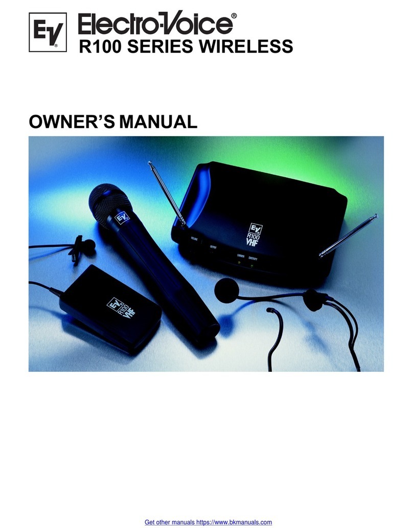
Electro-Voice R100 Series User manual

Electro-Voice

Electro-Voice R100 Series User manual

Electro-Voice RE3-BPOL User manual

Electro-Voice

Electro-Voice RE3-BPOL User manual

Electro-Voice R100 Series User manual

Electro-Voice

Electro-Voice R100 Series User manual

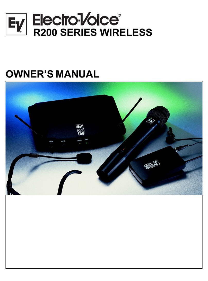
Electro-Voice R200 Series User manual

Electro-Voice

Electro-Voice R200 Series User manual

Electro-Voice 221-121 User manual

Electro-Voice

Electro-Voice 221-121 User manual

Electro-Voice MS2500 User manual

Electro-Voice

Electro-Voice MS2500 User manual

Electro-Voice MS2500 User manual

Electro-Voice

Electro-Voice MS2500 User manual

Electro-Voice Telex RE-2 User manual

Electro-Voice

Electro-Voice Telex RE-2 User manual

Electro-Voice R100 Series User manual

Electro-Voice

Electro-Voice R100 Series User manual

Electro-Voice MS2500 User manual

Electro-Voice

Electro-Voice MS2500 User manual

Electro-Voice Wireless Guitar System GS-2000A User manual

Electro-Voice

Electro-Voice Wireless Guitar System GS-2000A User manual

Electro-Voice Wireless Guitar System GS2500 User manual

Electro-Voice

Electro-Voice Wireless Guitar System GS2500 User manual

Electro-Voice Wireless Guitar System GS-1000 User manual

Electro-Voice

Electro-Voice Wireless Guitar System GS-1000 User manual

Electro-Voice REV-WT User manual

Electro-Voice

Electro-Voice REV-WT User manual

Electro-Voice Telex RE-2 User manual

Electro-Voice

Electro-Voice Telex RE-2 User manual

Electro-Voice REV User manual

Electro-Voice

Electro-Voice REV User manual

Electro-Voice R200 Series User manual

Electro-Voice

Electro-Voice R200 Series User manual

Electro-Voice MS3000 Series User manual

Electro-Voice

Electro-Voice MS3000 Series User manual

Electro-Voice CDR-1000 User manual

Electro-Voice

Electro-Voice CDR-1000 User manual

Electro-Voice MS-1000 User manual

Electro-Voice

Electro-Voice MS-1000 User manual

Electro-Voice R-Series User manual

Electro-Voice

Electro-Voice R-Series User manual

Electro-Voice REV User manual

Electro-Voice

Electro-Voice REV User manual

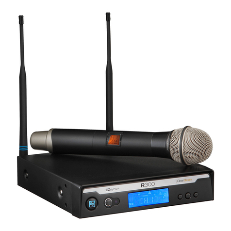
Electro-Voice R300 User manual

Electro-Voice

Electro-Voice R300 User manual

Popular Microphone System manuals by other brands

Samson CONCERT 88X owner's manual

Samson

Samson CONCERT 88X owner's manual

Vicon VF-1400 Series Installation & operation manual

Vicon

Vicon VF-1400 Series Installation & operation manual

Seht SM-1 user manual

Seht

Seht SM-1 user manual

SC&T Active Series user manual

SC&T

SC&T Active Series user manual

Sennheiser evolutionwireless G3 Short guide

Sennheiser

Sennheiser evolutionwireless G3 Short guide

Williams Sound Liberator One Instruction and user's manual

Williams Sound

Williams Sound Liberator One Instruction and user's manual

Shure KCX manual

Shure

Shure KCX manual

MikroTik Routerboard NetMetal 5 user manual

MikroTik

MikroTik Routerboard NetMetal 5 user manual

Panasonic WX-SA250P operating instructions

Panasonic

Panasonic WX-SA250P operating instructions

CAD Audio GXLD2QM owner's manual

CAD Audio

CAD Audio GXLD2QM owner's manual

Monacor AV-100SET instruction manual

Monacor

Monacor AV-100SET instruction manual

Samson XPDm owner's manual

Samson

Samson XPDm owner's manual

Shure Sistema Microflex MXCW manual

Shure

Shure Sistema Microflex MXCW manual

Azden Body-pack Transmitter 35BT Specifications

Azden

Azden Body-pack Transmitter 35BT Specifications

Av-Art WR-930A instruction manual

Av-Art

Av-Art WR-930A instruction manual

AKG WMS 470 - SERVICE User instructions

AKG

AKG WMS 470 - SERVICE User instructions

AT&T T1 installation and replacement

AT&T

AT&T T1 installation and replacement

Samson Stage v166 owner's manual

Samson

Samson Stage v166 owner's manual

manuals.online logo
manuals.online logoBrands
  • About & Mission
  • Contact us
  • Privacy Policy
  • Terms and Conditions

Copyright 2025 Manuals.Online. All Rights Reserved.