X-Array InstallTM Xi-1153/64 Loudspeaker System
X-Array Install
TM
Xi-1153/64 Loudspeaker System
2
The ISP-100 digital electronic unit was used
toprovidethenecessary crossover filters and
equalization during power testing. Specifi-
cally, the Xi-1153/64 passes the ANSI/EIA
RS426-A power test with the follwing test
parameters:
Low-Frequency Section:
PE(MAX): 600 watts
Test Voltages: 58.7 volts rms
117.4 volt speak
RSR(1.15 RE): 5.75 ohms
Mid-bass Section:
PE(MAX): 300 watts
Test Voltages: 45.5 volts rms
91 volts peak
RSR(1.15 RE): 6.9 ohms
High-Frequency Section:
PE(MAX): 75 watts
Test Voltages: 30.1 volts rms
60.2 volts peak
RSR(1.15 RE): 12.1 ohms
Crossover, Equalization And Time-
Delay Controller
The Xi-1153/64 speaker system and variants
are designed as an integrated package that
utilizes the Merlin ISP100, Klark Teknik
DN8000 or Electro-Voice Dx34A digital
crossover system. Optimal performance of
the Xi-1153/64 speaker system can only be
assured when using the above controllers.
For the three-way, non-overlap crossover
configuration, either the merlin ISP-100,
DN8000 or Dx34A may be used. For the
two-element-line-array configuration, how-
ever, only the Merlin ISP-100 may be used.
Electrical Connection And System
Wiring
Electrical connections to the Xi-1153/64 are
made on the back of the enclosure via a
8-pin connector. There are two connectors
on the input panel to allow paralleling of
other Xi-1153/64 systems. The Neutrik
Speakon®
NL8MPR is used for both connec-
tions. The pin assignments are as follows:
HF: Pin 4 In / Pins 4 Out
MB: Pin 3 In / Pins 3 Out
LF: Pin 1 In / Pins 2 Out
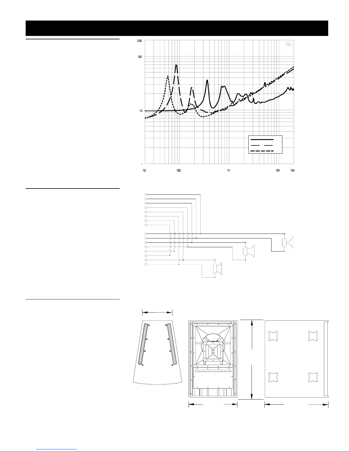
The wiring diagram of the loudspeaker
system is shown in figure 7. The electrical
impedance is shown in Figure 6.
Amplifier Recommendations
Power amplfiers with the following rat-
ings are recommended for use with the
Xi-1153/64 speaker systems:
LF: 600-800 watts continous into 8 ohms.
MB: 300-600 watts continous into 8 ohms.
HF: 125-250 watts continous into 8 ohms.
Xi-1153/64 speakers may be paralleled only
with other Xi-1153/64 speakers if the am-
plifier is capable of delivering full power at
the lower impedances. The use of amplifi-
ers with lower power ratings is acceptable;
however, the full-power capabilities of the
Xi speakers will to be realized. The use of
amplifiers with significantly higher power
ratings will generate maximum dynamic
range and fidelity, but care must be utilized
forlongerduration signals as mechanical and
thermal damage is possible in the system.
Flying the Xi Systems
A manual entitled the X-Array Install™ Fly-
ing Manual is available from Electro-Voice,
and is included with each flying Xi loud-
speaker system. A breif introductory over-
view is included here. The X-Array-Install™
Flying Manual should be consulted for com-
pletestructuralspecifications and detailed in-
formationonsafely suspending and using the
Xi systems.
The Xi systems incorporate a unique two-
pointflying system that permits a wide range
ofverticalangle adjustment, and offersmaxi-
mumflexibility in array design for both tour-
ing sound and permanent installations. The
quick-release, aircraft-rated heavy-duty
L-track-type hardware design allows arrays
of loudspeakers to be assembled (and disas-
sembled) very quickly, and offers such flex-
ibility in the vertical angling of cabinets that
pull-up points are usually unnecessary. Fur-
thermore, all of the flying Xi loudspeaker
models include the same rigging hardware,
allowing different models to be mixed as
necessary throughout an array.
Theworking-loadlimit (for an 8:1 safety fac-
tor) for each rigging point on the Xi loud-
speaker enclosure is 227 kg (500 lb) for a 0°
pull angle and 170 kg (375 lb) for a 90° pull
angle when used with the New Haven
NH32101-2 double-stud fitting, and 113 kg
(250lb)at any angle when used with theNew
Haven NH8192-2S or Ancra 42546-10
single-stud fittings with locking pins. The
working-load limit (for an 8:1 safety fac-
tor) for the overall enclosure is 453 kg
(1,000 lb). (Consult the X-Array Install™
Flying Manual for specific structural ratings
and limitations.) The enclosures may be ori-
ented with the rigging track on the sides of
the enclosure, or on the top and bottom, and
may be daisy-chained together as long as the
safety factor is 8:1 or greater, and local regu-
lations are met. For fire safety and additional
structuralstrengthin both flying orientations,
top-to-bottom and side-to-side metal straps
link the rigging track inside the enclosure.
All associated rigging is the responsibility
of others.
CAUTION: The Xi loudspeaker system
should be suspended overhead only in ac-
cordance with the procedures and limita-
tions specified in the X-Array Install Fly-
ing Manual and manual updates notices.
Field Replacment
Normal service for the Xi requires only a #2
Phillipsscrewdriveranda 3/16-inch hex-key
wrench. The drivers may be accessed as fol-
lows:
HF: First remove the grille, the remove the
screws securing the front flange of the high-
frequency horn. Peel the hook and loop
fastner strips from the four corners of the
foam shroud and remove the four sides of
the shroud. Lift the horn and driver out of
the wood assembly. In the event of failure,
thediaphragmassembly can be replaced with
the driver attached to the horn.
MB: Remove the screws securing the hatch
onthebackof the enclosure and lift the hatch
out.Remove the screws securing the 12-inch
woofer and lift the driver out of the enclo-
sure.In the event of failure, the entire woofer
must be replaced.
LF: First remove the grille, the remove the
screws securing the hatch on the front of the
enclosure. Remove the screws securing the
15-inch woofer and lift the driver out of the