ELECTRODRIVE Tug Tough 10T User manual
Tug Tough 10T
Operating Manual

Tug Tough 10T Operating Manual—OM0015E-1
This manual contains important safety, installation and operating instructions for this
unit. Read this manual thoroughly and completely, and retain for future reference. This
unit can cause serious injury to personnel or damage to property if used incorrectly,
therefore do not use this machine for any other purpose apart from its intended use.
Using this unit incorrectly may void warranty.
Any damage audible or visible to this unit should be addressed at the time of discovery.
Electrodrive Pty Ltd can provide parts and service support on request through its
service partner company:
Serviced Equipment Pty Ltd
p: 1300 934 471
e: service@fallshaw.com.au
Made in Australia by:
Electrodrive Pty Ltd
2A Ayton Street, Sunshine North VIC Australia 3020
p: 1300 934 471 (within Australia)
p: +61 (03) 9300 8521 (International)
w: www.electrodrive.com.au
© Electrodrive

Tug Tough 10T—Operating Manual
3
Contents
Introduction..................................................................................................................... 5
Features ....................................................................................................................... 5
Operating instructions ................................................................................................... 6
Controls ........................................................................................................................ 6
Driving instructions ........................................................................................................ 8
Safety Check ................................................................................................................ 8
Hitching to a trolley....................................................................................................... 9
Unhitching................................................................................................................... 10
Steering....................................................................................................................... 10
Charging ..................................................................................................................... 10
Maintenance ................................................................................................................. 11
Batteries...................................................................................................................... 11
Tyres............................................................................................................................ 11
Motor and transmission.............................................................................................. 11
Transmission ............................................................................................................... 11
Brakes......................................................................................................................... 11
Motor .......................................................................................................................... 11
Motor controller .......................................................................................................... 11
Throttle lever ............................................................................................................... 12
Fuses .......................................................................................................................... 12
Self-resetting circuit breaker....................................................................................... 12
Warranty ........................................................................................................................ 13
Unauthorised maintenance......................................................................................... 13
Misuse ........................................................................................................................ 13
General wear items not covered under warranty........................................................ 13

4
Appendix 1: Machine rating conditions...................................................................... 14
Appendix 2: Charging procedures for SLA batteries ................................................ 15
Appendix 3: Wiring diagram ........................................................................................ 16
Appendix 4: Spare parts list......................................................................................... 18
Service log .................................................................................................................... 20

Tug Tough 10T—Operating Manual
5
Introduction
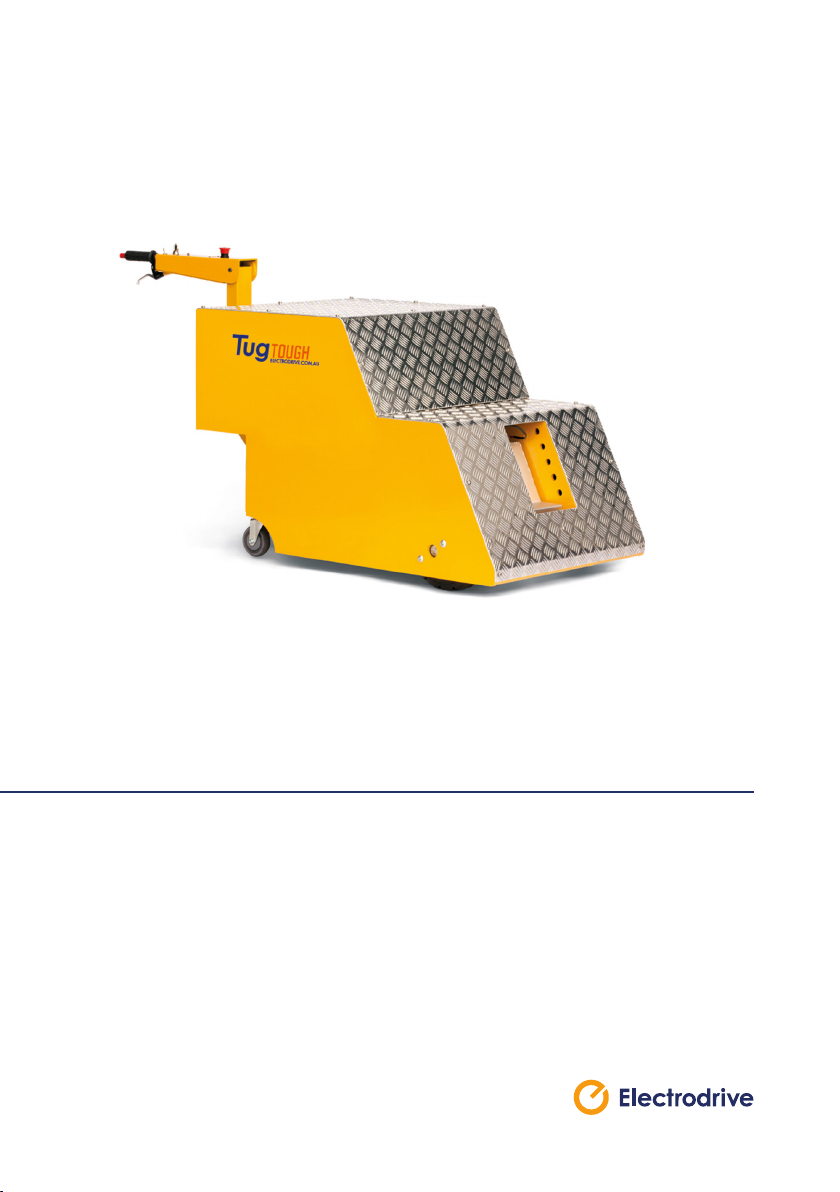
The battery powered industrial Tug Tough 10T allows an operator to effortlessly
move heavy wheeled loads and equipment, heavy duty construction, vehicles and
aircraft.
The Tug Tough 10T is a battery powered industrial truck for towing heavy trolleys. It
simply hooks on to your existing trolley with a lock-tow hitch. This converts your heavy
trolley into a powerful, easy to move motorised unit. Productivity is greatly increased,
and back or shoulder strain is eliminated.
This heavy duty model includes the latest developments in DC geared motors with
automatic dynamic braking, as well as a high capacity motor controller.
Features
§Rated to tow up to 10 000 kg
§24 Volt DC power
§Variable speed drive unit
§Electro-magnetic park brake
§Travel speed—up to 2.5 km/h
§Robust steel chassis
§Tiller handle steering that folds up to reduce space when not in use
§Programmable motor controller
§Automatic charger
§Speed governor
§Horn
§Quiet operation, ease of handling and high manoeuvrability
6
Operating instructions
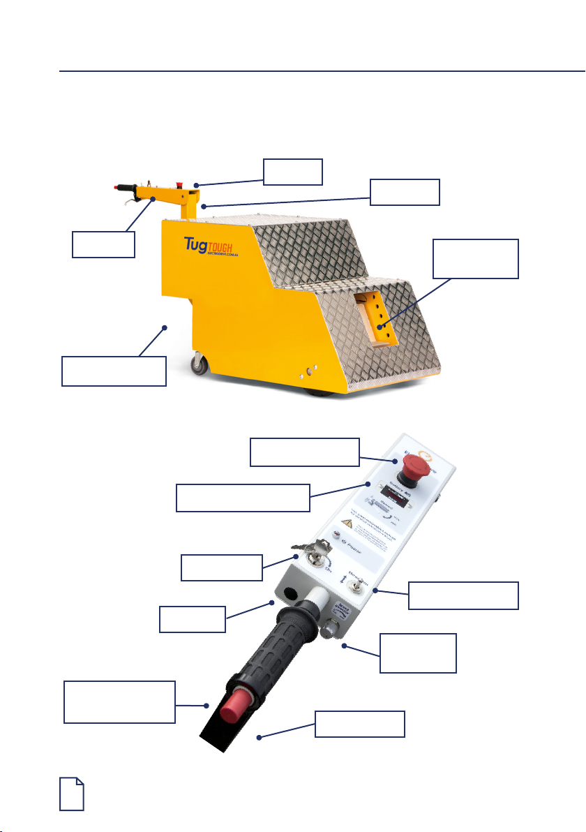
Controls
Lock-tow
hitch
Charger socket
Tiller arm
Tiller post
Key switch
Emergency stop
Emergency
back-off button
Direction selector
Speed
governor
Battery level indicator
Controls
Throttle lever
Horn

Tug Tough 10T—Operating Manual
7
Key switch
The key switch must be turned clockwise to switch the unit on. When ON, the LED
status indicator will be illuminated and the strobe light will ash. It is important to note
that the unit should be switched off and the key removed, whenever it is not in use. This
eliminates the risk of unauthorised movement and also prevents an unnecessary use of
battery power.
Emergency buttons
The controls have two emergency buttons.
1. Emergency stop button
In an emergency, push this button to stop the unit. To release, slightly twist the
button and it will pop back up.
2. Emergency back-off button
When pressed, the Tug will momentarily travel backwards to avoid pinning the
operator against an obstacle, and then stop if the throttle lever is not released. If
this button is pressed when the throttle is released, the Tug will immediately stop. To
reset the back-off function, toggle the direction selector.
Only use the emergency buttons in an emergency.
Battery level indicator
The battery level indicator indicates the amount of charge left in the batteries. When it
appears to be running low, return the unit to the closest charging station to charge the
batteries. Being aware of the level of charge of the batteries will eliminate the possibility
of running low on power whilst away from the charging station.
Direction selector
Toggle the switch to select the desired direction of travel (forward/reverse).
Speed governor
The speed governor limits the speed of travel. It can be adjusted from minimum (slow
walk) to maximum (brisk walk). It is recommended that you set the speed governor to
minimum when learning to operate this Tug, or when towing loads in conned spaces.
Throttle lever
This lever provides variable speed control from zero up to 100% of the governed speed.
Releasing the lever will cause the Tug to decelerate and stop within three seconds.
Charger socket
The plug on the charger is tted into the charger socket mounted on the body panel of
the Tug, next to the tiller post.

8
Brakes
When the throttle lever is released, the unit is slowed electrically by dynamic braking
until the machine and load comes to a complete stop.
Horn
The small yellow button on the console is a horn button. Push to sound the horn,
release to turn off.
Capacity
Refer to the serial plate for the unit’s safe working load, located on the body adjacent to
the tiller post.
Driving instructions
Safety Check
Before using the Tug the operator should complete the following check:
1. The battery charger is not connected.
2. The direction selector works.
3. The emergency stop button is released.
4. The battery isolator key is in the closed position (if tted).
5. The speed governing dial is set at ‘low’, or where desired by the operator.
6. The brakes operate correctly when the throttle lever is released.
7. The battery indicator shows adequate charge.
8. There is no visible damage to the unit.
9. Back-off button works correctly.

Tug Tough 10T—Operating Manual
9
Hitching to a trolley
This Tug has a variety of hitches. In all cases, ensure that the trolley it is being attached
to has its brakes engaged (or chocked), and is free from obstruction. Inspect the trolley
and ensure that the trolley castors are in good condition.
In all cases, ensure that the trolley being attached to has its brakes engaged (or
chocked) and is free from obstruction. Inspect the trolley and ensure that the trolley
castors are in good condition.
Towing a trolley with castors in poor condition can overload the Tug,
and cause damage not covered under warranty.
This Tug is not designed for use on inclined surfaces and doing so may
pose a risk of accident or injury. Use this Tug on level ground only.
771
1940
964
REV DCN/SI
DESCRIPTION
DATE
BY
CHD
APPD
3
-
GA
01/05/17
AD
LO
FQ
TOLERANCE REQUIREMENTS
Natural
Material <not specified>
Assembled
COLOUR
PROCESS
TREATMENT
FINISH
TOUGH TUG 10T GENERAL ARRANGEMENT
Dimensions in
milimeters unless
specified.
2A Ayton Street, North Sunshine, VIC 3020
Phone: (+61) 03 9300 8500 Fax: (+61) 03 9312 3441
Unless Otherwise Stated Are:
No Decimal Place = +/- 0.5
One Decimal Place = +/- 0.1
Two Decimal Places = +/- 0.05
TOLERANCES MUST NOT BE
CUMULATIVE UNLESS
OTHERWISE SPECIFIED.
Kg
LOCATION
DO NOT SCALE FROM DRAWING
REMOVE ALL BURRS & SHARP EDGES
DIMENSIONS MARKED WITH
ARE SIGNIFICANT INSPECTION DIMENSIONS.
MASS
1:20 1/1
MATERIAL
SCALE:
Part Number
PAGE:
SIZE:
A3
Rev
©
Monday, 1 May 2017
- This dimensioned drawing is the property of Electrodrive Pty Ltd. It is supplied only to aid the making of parts for Electrodrive, and must not be used against their
interests, supplied to 3rd parties, be copied, reproduced, used for manufacture or for any other purpose without the prior written permission of Electrodrive Pty. Ltd.
3
Description
TT10-R3-DUMMY
TUGTOUGH10TNH

10
Unhitching
Always make sure the trolley is on a at level surface and apply the castor brakes
(if tted) or chock the trolley wheels.
1. Unhook the hitch via the release handle.
2. Carefully drive the Tug forward away from the trolley.
Steering
The tiller arm provides easy steering. The Tug with an attached trolley can be
manoeuvred through relatively tight areas.
It is STRONGLY RECOMMENDED that the operator lead the Tug and
trolley, rather than using the Tug to “push” the trolley.
This will ensure that the operator has a safe unobstructed view ahead. This
will also make the Tug and trolley easy to manoeuvre.
Charging
Ensure regular recharging of batteries (charging overnight after a day’s usage is
recommended). Irregular charging may cause the batteries to prematurely fail.
Leaving a machine in storage without charge for periods greater than a month can also
lead to premature battery failure. This is not covered under warranty.
For detailed charging procedures refer to Appendix 2. Misuse of the battery will void
warranty.
Only use the battery charger supplied with this Tug.
The automatic features of the supplied charger ensures that the sealed gel
batteries are not overcharged, and only a minimum amount of gas, if any at
all, are expelled during charging.

Tug Tough 10T—Operating Manual
11
Maintenance
Batteries
If this unit is not being used for an extended period of time, it should be connected to
the battery charger to check the battery level on a regular basis, and placed on charge
overnight if required. This will ensure the batteries are kept in good condition.
The batteries are sealed and maintenance free. DO NOT attempt to open these
batteries. If the unit is not charged as above, the batteries may be exhausted and have
dropped below the charging threshold of the battery charger. The supplied charger
cannot begin to charge the batteries unless they have a small amount of charge. If this
occurs, contact Electrodrive or your local service agent.
A sign that the batteries need replacing is when they no longer hold charge.
Tyres
The tyres are a press on band – similar to those used on forklifts and other material
handling equipment. They are puncture resistant. For replacement tyres, please refer to
the spare parts section in this document or contact Electrodrive.
Motor and transmission
The transaxle is a sealed unit and does not require regular maintenance.
Transmission
The tension in the transmission chain should be checked every three months. Ensure
that the chain has no more than ±10 mm deection. Light lubrication can also be
applied in three month intervals.
The gear boxes are sealed and do not require service.
Brakes
The dynamic braking system does not require regular maintenance.
Motor
Motor brushes should be inspected every six months and replaced every two years.
Remove the brush retaining cover for access to the brushes, should they need
replacing.
Motor controller
This unit is not serviceable. Any difculties experienced with speed control should be
referred to Electrodrive.

12
Throttle lever
The throttle lever and cable do not require maintenance. Should the lever or cable suffer
damage they should be replaced. If the handle loosens with wear, the hinge nut can
be gently tightened. However, rst conrm that the lever is in the correct position as it
may need to be reset. (Test by squeezing the lever slightly. The Tug should slowly move,
release and the Tug should completely stop).
Fuses
The control circuit is protected against inadvertent current over-loads. This fuse is
located adjacent to the controller under the top cover.
Self-resetting circuit breaker
The Tug is tted with a self resetting circuit breaker in case of momentary overload. This
circuit breaker can be found beneath the top cover on the main electrical control panel.
If the unit repeatedly overloads, test the machine, as the motor may be damaged, and
continued use could damage the unit further.

Tug Tough 10T—Operating Manual
13
Warranty
Electrodrive Pty Ltd warrants that this product is free from defects in materials and
workmanship for a period of twelve months from the date of dispatch from the
Electrodrive plant. The battery has a six month warranty.
If a defect is reported, Electrodrive will repair or replace the defective part, at its own
discretion. This warranty does not apply if this unit has been misused, damaged, or
modied in any way.
Please be aware that modications and misuse will void your warranty. The following
activities (including, but not limited to) are examples of these:
Unauthorised maintenance
§The machine is re-wired by an unauthorised service agent
§The motor controller is re-programmed by an unauthorised service agent
§There are modications to the body or frame of the machine
§Use of non-specied parts
§The machine is serviced by an unauthorised service agent
Misuse
§Shunting loads at speeds in excess of 2 km/h
§Overloading the unit either during towing or lifting
§Carrying people or other foreign objects
§Exposed to rain or other precipitation, unless weatherproof option is installed
§Using the emergency back-off system to change direction regularly
§Exposed to a corrosive environment
§Driven off road—potholes, gravel, etc.
§Driven on slopes
§Not being charged adequately
§Using the emergency stop button as an ON/OFF button
General wear items not covered under warranty
§Tyres, tubes and castors
§Drive wheels and motor brushes
§Hand grips
14
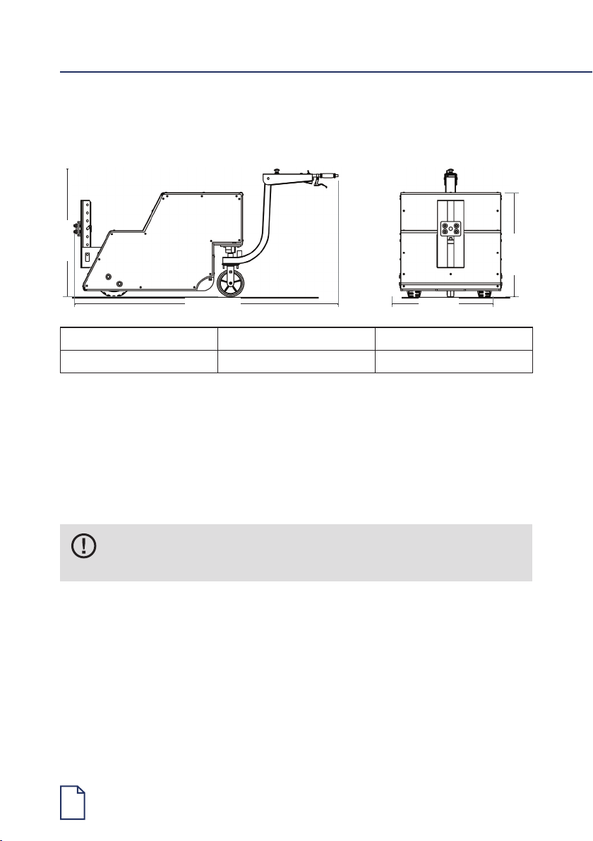
Appendix 1: Machine rating conditions
Model Working Load Limit Max Load
TUGTOUGH10T 10,000 kg 10,000 kg
The Tug Tough 10T has been designed to move the rated weight capacity on a level rm
surface. Variations in the working environment may impede the performance of this unit.
Such parameters include (but are not limited to) the following:
• Ramps and sloped surfaces
• Soft surfaces (for example carpet)
• Slippery surfaces (gravel, water, oil on the ground, etc.)
It is important that the Tug Tough 10T IS NOT to be operated outside of
the recommended conditions.
1912 mm
910 mm
650 mm
790 mm

Tug Tough 10T—Operating Manual
15
Appendix 2: Charging procedures for
SLA batteries
§Always charge batteries when work is complete and the equipment is not required for
use.
§Opportunity charging is NOT recommended. This can also shorten battery life.
§Never leave batteries in a discharged state as this will shorten the batteries life.
§For maximum battery life, a battery must be recharged to 100% capacity. Recharging
less than 100% may result in premature battery failure. Batteries are not covered
under warranty if they are not recharged properly.
§If batteries are disconnected from the machine and not used for lengthy periods of
time, it is recommended to give them a maintenance charge once every two months.
Charging setup
§Ensure you have the correct charger for the batteries. The correct voltage and current
is important to ensure the full life of the batteries.
§Check all connections are tight and in good condition.
§The green charger LED will illuminate to conrm charging is in progress.
§If charger lights do not come on, call your service technician.
§When charger is plugged in, drive function of machine is automatically inhibited.
During charging
§Ensure there is enough airow to help keep the batteries as cool as possible.
§If the batteries are swollen turn off immediately and call your service technician.
§Always leave batteries on charge until the charge is COMPLETE. This is indicated
when charger LED turns off.
Charger manual
Please read BA1105—Battery Charger Operating Manual for more information.

16
Appendix 3: Wiring diagram
10

Tug Tough 10T—Operating Manual
17
10

18
Appendix 4: Spare parts list
Part (mechanical) Description
PC1180 Tiller handle backing plates p
PC1160 Tiller Handle—yellow PC no s
WP4012 TT elec panel tow only dynamic
MO1145 Motor S5 375W 2800RPM D71B14
GM1673 G/b NMRV063 i20 D71B14
GM1702 G/Box NMRV063 output shaft
SP1025 Sprkt 12T bossed 10B
SP1185 Sprkt 30T bossed 10B
GM1410 Chain 10B1, 5/8
CS1030 Castor 100mm, grey
CS1190 Castor 200mm, grey PU
PC1240 Tiller post bent bent
GM1850 Hub—A400 Ford 1/2
BA1021 Battery 12V 55Ah AGM
BA1120 Charger 48V 15 amp
GM1470 Chain link 5/8 pitch
WH1460 Tyre press on 10x4x6—1/2
WH1185 Rim—one piece 5 bolt suit press on tyre
GM2018 Shaft—drive TT tow
GM1225 Bearing TT10 tow 35mm shaft
GM1142 Bearing housing TT10 tow
WP1135 Tiller arm—yellow TT version
EL3210 Socket—3 pin charger
WP1141 Tiller post—bent fab
PC1240 Tiller post bent bent
WP4012 TT elec panel tow only dynamic
EL1980 Contactor main 48V
EL1970 Contactor F/R 48V

Tug Tough 10T—Operating Manual
19
Part (electrical) Description
EL2000 Contactor mounting bracket
EL3130 Resistor 500W 1ohm
EL2310 DIN rail part KST5
EL2320 DIN rail part KST8
EL2450 Fuse 1 amp 3AG1
EL2470 Fuse 10 amp
EL2500 Fuse holder panel mount
EL3100 Relay 24volt
EL2030 Controller 1204-402
EL2336 Duct—slotted duct 60x60
EL1920 Circuit breaker 80 amp
EL2515 Blade fuse holder maxi
EL2516 Blade fuse holder maxi cover
EL3127 Relay 24V DC time delay

20
Service log
Service recommendations
To ensure this equipment is kept in a safe and reliable condition, it is important to
follow a preventative maintenance program. Maintain a log of the service work on the
cards below, and always use an approved Electrodrive service agent to conduct the
works. Approved service personnel will be provided with all necessary documents and
components in service repair, including but not limited to, circuit diagrams, component
part lists, descriptions, service checklists and spare parts.
6 month service
Date of service Service agent
Machine serial number
Summary of works
Next service due
Table of contents
Other ELECTRODRIVE Jack manuals


Popular Jack manuals by other brands

Black Hawk Automotive
Black Hawk Automotive BH6023 Operating instructions & parts manual

Metalworks
Metalworks 754752220 manual

U.S. General
U.S. General 91039 Assembly and operating instructions

Black Hawk Automotive
Black Hawk Automotive BH6034B operating instructions

ATD Tools
ATD Tools ATD-7345B owner's manual

Toparc
Toparc 064126 Translation of the original manual

OTC
OTC 1546 PARTS LIST & OPERATING INSTRUCTIONS

ATD Tools
ATD Tools 7425A owner's manual

K Tool International
K Tool International KTI-XD61202 owner's manual

Tractel
Tractel top BT 1.5 Operating and maintenance instructions

Super Handy
Super Handy GUT045 manual

Power Jacks
Power Jacks E Series Operation & maintenance instructions


