INTRODUCTION/GENERAL INSTRUCTION
23
2
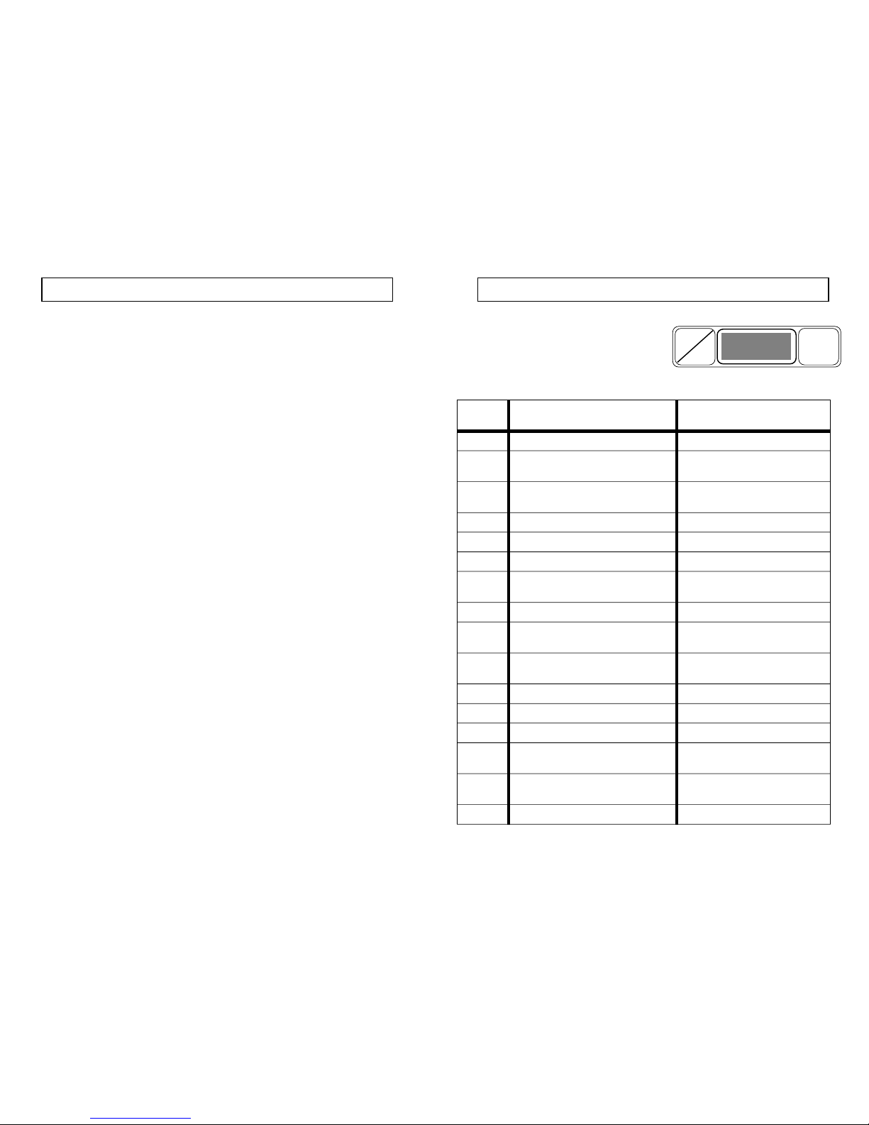
ERROR CODE MEANINGS
If the error code indicator flashes a problem
has arisen or is imminent. Read the code in
the display to recognise the problem and
decide what action is necessary.
CODICE
ERRORE
PROBLEM POSSIBLE CAUSE
300 High traction wheel brake temperature Check brake pad drag
301 Traction shut-off due to wheel brake
high temperature
-Ditto-
302 Traction motor output transistor/s
faulty
Check for motor fault before
replacing P.C.B.
303 High current in traction circuit Check overload in traction
304 Traction output transistors = 85° C -Ditto-
305 Traction output transistors = 95° C -Ditto-
306 Traction output transistors = 105° C
(shut-off)
-Ditto-
307 Faulty accelerator potentiometer Replace potentiometer
308 Broken accelerator potentiometer
cable
Replace cable
402 Brush motors output transistor/s faulty Check for motor fault before
replacing P.C.B.
403 High current in brush motor circuit Check overload in brush motors
404 Brush motors output transistors = 85°C -Ditto-
405 Brush motors output transistors = 95°C -Ditto-
406 Brush motors output transistors = 85°C
(shut-off)
-Ditto-
602 Brush motors output transistor/s faulty Check for motor fault before
replacing P.C.B.
700 24v supply missing Check fuses
H
P
ERROR
CODE
GENERAL RULES OF SAFETY
The information below must be followed carefully in order to avoid injury to the operator, or
damage to the machine.
- Read the labels carefully on the machine, do not cover them for any reason and replace them
immediately if damaged.
- Do not mix different detergents to avoid the possible production of dangerous gasses.
- Do not place any liquid containers on the machine.
- The storage temperature should be between 25°c and 55°c.
- The operating temperature should be between 0°c and 40°c.
- Humidity should be between 30% and 95%.
- Do not use the machine in explosive atmospheres.
- Do not use the machine as means of transport.
- Do not use acid solutions which could damage the machine.
- Avoid operating the brushes when the machine is standing still, in order to prevent floor
damage.
- Do not pick up inflammable liquids with the squeegee.
- In case of fire, use a powder extinguisher. Do not use water.
- Avoid shelving or scaffolding, where there is danger of falling objects.
- Adapt the operational speed to the surface adhesion conditions.
- Do not allow the machine to tip sideways along a gradient greater than 2% in order to avoid
conditions of instability (2% max).
- Mark out the cleaning area with “WET FLOOR” warning signs, particularly in public areas.
- If the machine does not work properly, check by conducting simple maintenance procedures.
Otherwise, it is better to ask for technical service.
- Where spare parts are required contact ELECTROLUX EUROCLEAN or a local distributor for
genuine original parts, or ask for on site technical service.
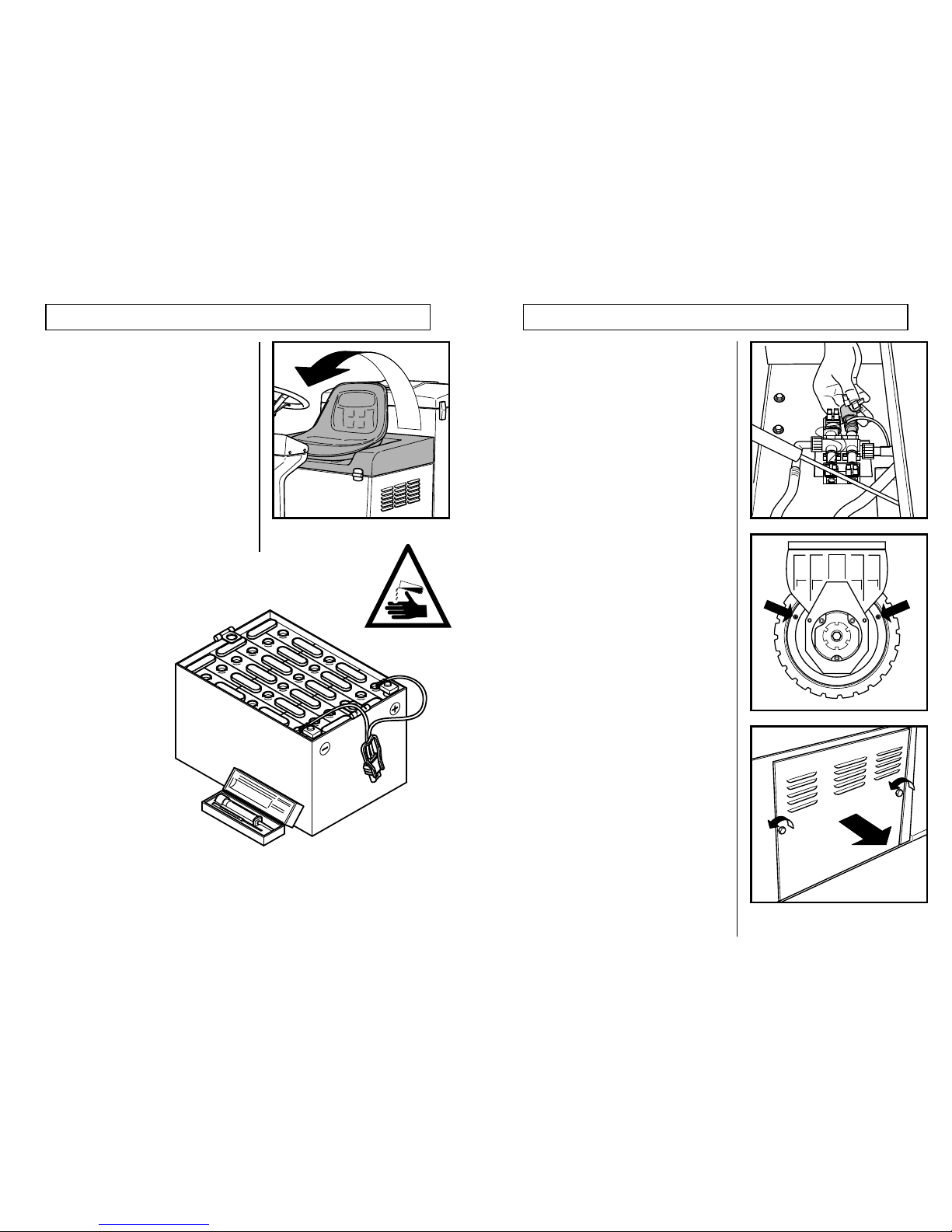
- Remove the battery connector before carrying out any maintenance on the machine.
- Do not remove items which require the use of tools to be removed.
- Do not wash the machine with direct water jets or with high water pressure or with corrosive
detergents.
- Every 200 working hours have a machine maintenance check by a technical service
department.
- The machine should not be abandoned, because of the presence of toxic-harmful materials
(batteries, oil etc). This disposal must be subject to the regulations which provide for its
scrapping in appropriate centres.
The machine does not cause any harmful vibration.