Trinity Amps THOR User manual

The Trinity Amps
THOR
Amp Builder's Guide
DRAFT VERSION
October 2021, Version 21.3
For the sole personal use of Trinity Amps Customers.
Parts © Trinity Amps 2005 - 2021
www.trinityamps.com


Table of
Contents
Table of Contents.................................................................................................................................. 3
Thank You! ........................................................................................................................................... 5
Introduction .......................................................................................................................................... 7
Acknowledgements............................................................................................................................... 7
WARNING ........................................................................................................................................... 8
Version Control ..................................................................................................................................... 9
Builders Guide General Theory ............................................................................................................ 9
Building an Amp..................................................................................................................................10
Introduction...................................................................................................................................................................... 13
Switches and wire............................................................................................................................................................. 13
Physical layout .................................................................................................................................................................. 13
Grounding......................................................................................................................................................................... 13
Insulated jacks .................................................................................................................................................................. 14
Minimizing transformer interference ........................................................................................................................... 14
Wiring ................................................................................................................................................................................ 14
Assembling the amp ............................................................................................................................14
Before You Begin ............................................................................................................................................................ 14
Tools .................................................................................................................................................................................. 14
Soldering............................................................................................................................................................................ 15
Tube Pin Numbering ...................................................................................................................................................... 15
Tube Designations........................................................................................................................................................... 16
Grounding Scheme ................................................................................................................................................. 17
Assembly Steps Summary ....................................................................................................................19
1. Install the Hardware .............................................................................................................................................. 20
Tube Sockets............................................................................................................................................................ 22
Can Capacitor .......................................................................................................................................................... 22
Grommets ................................................................................................................................................................ 22
Front Panel............................................................................................................................................................... 22
Terminal Strips ........................................................................................................................................................ 22
Ground Lugs............................................................................................................................................................ 23
Impedance Switch................................................................................................................................................... 23
Output Jacks ............................................................................................................................................................ 23
IEC Mains Socket ................................................................................................................................................... 23
Fuse Holder.............................................................................................................................................................. 23
1. Install Transformers .............................................................................................................................................. 24
2. Heater Wiring ......................................................................................................................................................... 24
Heater Wires ............................................................................................................................................................ 24
3........................................................................................................................................................................................... 26
4. Wire the Power Supply ......................................................................................................................................... 26
120V MAINS........................................................................................................................................................... 29
240V MAINS........................................................................................................................................................... 30
RECTIFIER WIRING (SS/5AR4)..................................................................................................................... 31
HV WIRING........................................................................................................................................................... 31
Test the Power Supply ........................................................................................................................................... 33
5. Assemble the Turret Board .................................................................................................................................. 34
Install Components on Turret Board .................................................................................................................. 34
Install the Turret Board ......................................................................................................................................... 37
6. Connecting the Turret Board............................................................................................................................... 38
Bias and Power Supply........................................................................................................................................... 38
.................................................................................................................................................................................... 39
Pay attention to the orientation of the diode and bas filter capacitors.......................................................... 39
Tube Sockets............................................................................................................................................................ 40

Trinity Amps THOR Builder’s Guide. Version 21.1
Page - 4
Socket Mounted Parts ............................................................................................................................................ 41
Phase Inverter Socket............................................................................................................................................. 41
6V6 Power Tube Wiring –Bias Resistor, Screen Resistor ............................................................................. 42
Connecting Controls - Potentiometers ............................................................................................................... 42
7. Output –Transformer, Impedance Switch, Jacks............................................................................................ 44
Output Jacks ............................................................................................................................................................ 46
8. Input - Jacks and Input Grid Resistors .............................................................................................................. 47
Input Grid Resistors ............................................................................................................................................... 47
Input Jacks................................................................................................................................................................ 47
Preparing Co-Axial Wire........................................................................................................................................ 49
Final checkout .................................................................................................................................... 50
Power Up .............................................................................................................................................51
Working Inside A Tube Amplifier Safely .................................................................................................................... 51
Unplug....................................................................................................................................................................... 51
Sit ............................................................................................................................................................................... 51
Drain.......................................................................................................................................................................... 51
Test ............................................................................................................................................................................ 51
Close .......................................................................................................................................................................... 51
Making a Voltage Measurement.................................................................................................................................... 52
Trinity Thor Voltage Chart ................................................................................................................. 54
Trinity Thor Voltage Chart ................................................................................................................. 55
Read this Information Carefully ........................................................................................................................... 56
Builders Guide General Troubleshooting ........................................................................................... 56
Tweaking the Thor Overdrive Intensity and Tone.................................................................................................... 57
How to read Resistor Color Codes...................................................................................................... 59
First the code ........................................................................................................................................................... 59
How to read the Color Code ................................................................................................................................ 59
How to Read Capacitor Codes ........................................................................................................... 60
FAQ .................................................................................................................................................... 62
Cliff Jacks Explained .......................................................................................................................... 65
THOR Bill of Material (BOM) ........................................................................................................... 66
THOR Transformer Hook Up Schematics ........................................................................................ 69

Thank You!
Thank you for purchasing your kit from Trinity Amps. We truly hope that you enjoy building it. If
you have any questions please do not hesitate to contact us.
We are always looking for feedback form our Customers on our products. We have checked the
build instructions over thoroughly and are confident in our product. However, mistakes do happen
so our advice is that as you connect each wire and part according to the layout, cross-check against
the schematic. If you find any inconsistencies, or have any concerns, please let us know. Do not
hesitate to contact us! We want this build to be successful for you and for Trinity Amps!
Please check over your parts carefully and the Bill of Materials and notify us of anything that does
not seem correct.
We’re confident that you will like our product and our support and when you’re completed, we’d
appreciate your comments posted on any of the internet forums such as thegearpage.net,
18watt.com, AX84.com or trinityamps.com. You will find some extra business cards in the package.
Please keep one and pass the rest around.
We know you have a choice in suppliers and we do appreciate your business.
Have Fun!!
Cheers,
Stephen Cohrs,
Trinity Amps
Web site: www.trinityamps.com
email: [email protected]


Introduction
This guide has been prepared for builders of Trinity Amps Kits. It is always being improved and we
Accordingly, content and specifications are subject to change without notice.
We do try to make it as accurate as possible, but it is sometimes hard to keep up with the changes.
Therefore, if you do find an error, please let us know about it and we will correct it. Suggestions are
welcome so if you have one, please get in touch with us.
Sources of help.
Forums: Please use the various forums to get help. They are an excellent resource and can be found
at trinityamps.com, AX84.com, the Gear Page etc..
Color assembly pictures and the latest drawings, tips, techniques are all in the Trinity Amps Forum,
in the Resources Forum.
Email: We can’t help with every problem but if you cannot get your problem resolved, email us and
we’ll do our best to help.
Phone Call: If your problem can’t be solved, email for a phone appointment.
Acknowledgements
Much of the content in this document is original. Rather than reinvent content, some parts are
based on content from other excellent sources and are hereby acknowledged.
Thor based on original work by RobRobinette.com
R.G. Keen’s site www.geofex.com - Tube Amp FAQ, Tube Amp Debugging
AX84.com site www.AX84.com - Gary Anwyl's P1 construction guide version 1.0
GM Arts website http://users.chariot.net.au/~gmarts/index.html - Guitar Amp Basics
www.18watt.com - website for various content and diagrams –Richie TMB
Aron from diystompboxes.com
Parts © Trinity Amps. No part of this document may be copied or reprinted without written
permission of Trinity Amps or contributing authors listed above.

Trinity Amps THOR Builder’s Guide. Version 21.2
Page - 8
WARNING
Please Read this Information Carefully
The projects described in these pages utilize POTENTIALLY FATAL HIGH VOLTAGES. If
you are in any way unfamiliar with high voltage circuits or are uncomfortable working around high
voltages, PLEASE DO NOT RISK YOUR LIFE BY BUILDING THEM.Seek help from a
competent technician before building any unfamiliar electronics circuit. While efforts are made to
ensure accuracy of these circuits, no guarantee is provided, of any kind!
USE AT YOUR OWN RISK: TRINITY AMPS EXPRESSLY DISCLAIMS ALL LIABILITY FOR
INJURY OR PROPERTY DAMAGE RESULTING FROM THIS INFORMATION! ALL
INFORMATION IS PROVIDED 'AS-IS' AND WITHOUT WARRANTY OF ANY KIND.
REMEMBER: NEVER OPERATE YOUR AMP WITHOUT A LOAD. YOU WILL RUIN
YOUR OUTPUT TRASNFORMER!
Trinity Amps THOR Builder’s Guide. Version 21.2
Page - 9
Version Control
Version
Date
Change
21.1
19Sep21
Draft Version
21.2
10Oct21
Reversed OT wires connection to tube sockets

Trinity Amps THOR Builder’s Guide. Version 21.2
Page - 10
Builders Guide General Theory
For a discussion on Guitar Amp Basics and Tube Amp Theory, please refer to our Web-Site
Support Page document Builders Guide General Theory
Marshall High Gain Amps
extracted from www.robinette.com
Introduced in 1974, the "Master Volume Lead" series amps were Marshall's first true high gain
amplifiers. They cascaded the Plexi's bright channel into the normal channel, added a pre-phase
inverter master volume and cold biased "cold clipper" gain stage and tweaked the resulting circuit
for an aggressive but sweet overdrive tone.
The guitar signal enters the High "Lead" Channel input jack. The signal is amplified by the V1B
preamp stage then flows through the Preamp Volume pot to the V1A cold biased "cold clipper"
gain stage which generates asymmetric clipping. The signal then flows through the V2A preamp
then directly through DC coupling (no coupling cap) to the V2B cathode follower which supplies
the tone stack with a low impedance signal to keep the tone stack from loading down the guitar
signal. After the Tone Stack the signal goes through the Master Volume and into the Phase Inverter.
The Phase Inverter creates two mirror image signals that are 180 degrees out of phase to feed to the
Power Tubes.
The "High Sensitivity" or "Lead" Channel has an extra preamp gain stage compared to the Low
Channel. The guitar signal is amplified by V1B (one 12AX7 triode) which has a cool bias from its
2.7k cathode resistor. Its small .68uF bypass cap boosts the gain of mid and high frequencies which
reduces the High Channel's lower frequencies early in the circuit so it can focus on mids and highs
that sound good when later stages push into heavy distortion. The signal then flows through the
Low Channel input jack (where the Low Channel input would start) to the Preamp Volume pot. The
pot's output flows to the V1A "cold clipper" gain stage.
The Cold Clipper
The cold clipper is very important to these Marshall high gain amps' smooth overdrive tone. For
minimum distortion a tube should be biased halfway between cutoff (when all electron flow is
stopped) and saturation (when electron flow is maxed out). A 1.5k cathode resistor for a typical tube
amp 12AX7 triode gain stage is very close to center bias. The cold clipper's very large 10k cathode
resistor sets a cold bias that leaves little room on the shutoff side so the input signal can easily be
clipped when the input signal's negative lobe on the grid reduces electron flow through the tube and
electron flow is shutdown completely. This clipping is asymmetric because there's plenty of room on
the saturation side of the bias point. Asymmetric clipping generates mostly sweet-sounding 2nd
harmonic distortion. The positive, saturation side of the guitar signal lobe isn't distorted and carries
the original musical content.

Trinity Amps THOR Builder’s Guide. Version 21.2
Page - 11
The JMC800 uses a cold clipper stage with an unbypassed 10k cathode resistor. Soldano liked to use
a more aggressive 39k cathode resistor for an even colder cold clipper. The following gain stage is
biased warm with an 820 ohm cathode resistor. Since a guitar signal's phase if flipped after each gain
stage putting a warm biased stage after the Cold Clipper helps keep the distortion asymmetrical by
keeping the undistorted lobe clean.
Asymmetric clipping tends to sound smoother and creamier than symmetric clipping where both the
+ and - signal lobes are clipped equally. With asymmetric clipping one signal lobe carries the clean
signal while the clipped lobe carries the distortion. The cold clipper generates early, relatively low
volume, smooth, musical preamp distortion that can be controlled by the Master Volume for high
gain tone at lower volume than their earlier non-master volume amps. Without the cold clipper stage
the preamp would stay too clean and the amp would have to rely on distortion from the power amp
making the Master Volume less useable. As the cold clipper distortion comes on it blends seamlessly
into the downstream phase inverter and power tube distortion into a cacophony of delicious high
gain tone.
The cold clipper's asymmetric output signal can be clipped in later gain stages at high volume levels
but note the gain stage following the Cold Clipper is biased warm with an 820 ohm cathode resistor
(V2A). Because a guitar signal's phase if flipped after each gain stage, putting a warm biased stage
after the Cold Clipper helps keep the distortion asymmetric by keeping the guitar signal's undistorted
lobe clean. The warm bias leaves more room on the cutoff side to reduce clipping to the undistorted
signal lobe.
The cold clipper is also a relatively low gain stage compared to one with a fully bypassed cathode.
Soldano used the cold clipper cathode resistor value to trim gain to make his preamp work as
desired. The higher the resistance value the lower the gain. That's one of the reasons Soldano used
such a very large (39k) cathode resistor in his cold clipper.
The Attenuator Circuits
After the first preamp stage the guitar signal flows into an attenuating voltage divider. The OD
Channel divider is made up of a 470k Attenuator resistor + the 500k OD Gain pot. Attenuating
voltage dividers are an important part of high gain amp tone. This divider dumps 48% of the guitar
signal to ground to keep from over overdriving the following gain stages. Signal attenuating voltage
dividers are present in all high gain tube amps to control the level of overdrive and saturation. The
Attenuator resistor is bypassed with a 470pF Bright cap (also called a Treble Peaker) to allow high
frequencies to go around the voltage divider to boost high frequencies. Low and mid frequencies are
cut by 48% by the attenuating voltage divider while high frequencies are not cut. If you remove or
bypass the upper resistor in a voltage divider then there is no voltage divider. Removing this Treble
Peaker cap is a common mod for overly bright amps to cut ice pick highs and reduce shrillness.
There are four other attenuating voltage dividers in the OD and Clean Channels that moderate gain
to keep things under control at high gain settings.
The Treble, Mid & Bass (TMB) Fender style tone stack uses variable RC filters to block high, mid
and low frequencies. It's a passive tone control that cannot boost frequencies, only remove them
from the guitar signal. It's a low impedance circuit that places a heavy load on the guitar signal so the
V4A Tone Stack Buffer Cathode Follower acts as a buffer between the low impedance tone stack
and the high impedance signal from the preamp. Without the cathode follower the tone controls

Trinity Amps THOR Builder’s Guide. Version 21.2
Page - 12
would raise and lower the overall signal volume even more than they already do. The guitar signal
leaves the tone stack through the treble pot's wiper and flows to the Master Volume pot.
The Master Volume is a pre-phase inverter master volume that controls the signal level flowing into
the phase inverter and controls the distortion level of both the phase inverter and the power tubes.
The 12AX7 phase inverter gets hit with a hot signal from the preamp and being able to tame that
signal before it hits the inverter's grid can help prevent unwanted blocking distortion at extreme
volume levels. The down side of having the master volume on the input side of the phase inverter is
you don't have the phase inverter's gain to create distortion before the master volume.
The "Low Sensitivity" or "Normal" Channel
The Normal Channel's guitar signal bypasses the High Channel's first gain stage V1B and flows
directly to the Preamp Volume pot then on to the V1A Cold Clipper gain stage. From there it
follows the same path as the High Channel described above. With one less preamp gain stage the
Normal Channel has more clean headroom and tends to be more pedal friendly.
Output Stage
The large 1 kilohm 5-watt screen resistors are required to control the screen current that flows from
the EL34 true pentode's screen under heavy power tube overdrive. A true pentode flows more
screen current than a beam tetrode such as the 6L6 and 6550 tubes. The screen voltage drop caused
by the voltage drop across the screen resistor during heavy overdrive is the main difference in
overdrive tone between the EL34 and beam tetrode tubes. If you want Marshall style power tube
overdrive you need to use EL34's with 1k 5-watt screen resistors.
Amps bound for the USA had 6550 power tubes so the 56k bias resistor shown above was reduced
to 47k and the 220k grid leak resistors were reduced to 150k.
The power supply's solid-state rectifier and the use of a choke between the power tube plate and
screen power nodes offers up minimal dynamic voltage sag to keep the overdrive tone tight and
reduce the chance of power supply induced oscillation.

Trinity Amps THOR Builder’s Guide. Version 21.2
Page - 13
Building an Amp
Warning: Do not attempt to build a guitar amp unless you know how to work safely with the
dangerous voltages present in a tube amp. These voltages can exceed 700 volts.
Introduction
If you have purchased your Trinity Amp as a kit, this guide will help you build a tube guitar
amplifier. It is oriented towards someone who knows a little about electronics but is new to do-it-
yourself amps. It outlines a simple path to getting a quality amp build.
Switches and wire
Use standard UL approved switches with a 125V/3A rating for the Power and Standby switches.
Use 22 or 20 Gauge insulated solid wire with a 600V rating. It is good to get a variety of colors so
you can color code your wiring.
Physical layout
Make sure the jacks, sockets and pots mounted along the edge won't interfere with parts mounted
on the underside of the chassis. Imagine how chassis will be mounted in the cabinet and make sure
there is enough clearance for the speaker and mounting brackets. Trinity amp chassis are laid out
with serviceability and neatness in mind.
Grounding
It is recommended that you follow the layout provided with your Trinity Amp. It has been tested
and has proven reliable. If you choose to deviate, consider the following information.
Amps traditionally use the chassis for signal ground. This is not the best choice since it can create
ground loops and bad ground connections may develop over time. It is better to use star grounding
in which all of the local grounds are collected at a single ‘star ground’ point. With star grounding
there is only one connection between the chassis and signal ground.
Here are some rules for laying out a star ground. More information on grounding can be found in
the Tube Amp FAQ and the Tech Info page of Aiken Amplification.
(1) Connect the power transformer center tap directly to the negative terminal of the first power
supply filter capacitor (cap) then run a separate wire from the negative terminal to the star ground
point.
(2) Collect the ground points of each tube and its associated resistors and capacitors to a local
ground point that is not connected to the chassis. Run one wire to the star ground point from each
collection.
(3) Run exactly one wire from the star ground point to chassis.
(4) Insulate the input and output jacks from the chassis.

Trinity Amps THOR Builder’s Guide. Version 21.2
Page - 14
The safety ground wire from the mains is separate from the signal ground. Run a wire from the AC
ground to the chassis near where the AC power enters the chassis.
Insulated jacks
To insulate the input and output jacks either use plastic insulated jacks or metal jacks with insulating
washers. Some people prefer the increased durability of metal jacks. Insulating a metal jack requires a
shoulder washer with a 3/8’ internal hole that fits a ½’ panel hole.
Minimizing transformer interference
To minimize coupling between the power transformer and output transformer orient them so their
plates are at right angles. If possible, place them at opposite ends of the chassis.
Keep the input stage wiring short and away from the output stages. This minimizes the possibility of
oscillations caused by coupling of the output signal into the input.
Mount the grid resistors as physically close to the grid pins as possible.
Use a twisted pair of wires for the tube filament wiring. Route it away from AC lines and close to
the chassis.
Wiring
The traditional method of constructing amps involved mounting the components on tag board or
fiberboard. This is the technique that is used for Trinity Amplifiers and is the recommended
approach for service and reliability.
Assembling the amp
Before You Begin
When you first receive your kit, remove all of the parts from the shipping box and place them on a
well-lit, clean surface. Check all of the parts against the parts list and verify that you have everything
before you begin. Contact us at once if you are missing anything, or if something appears to be
damaged.
Tools
To assemble the amp you need:
1. 25 watt pencil tip soldering iron. (Minimum for ROHS)
2. 60/40 rosin core solder .030” dia (lead-free 97/3 tin/copper for ROHS turrets)
3. wire stripper
4. wire cutter
5. needle nose pliers
6. small screwdrivers (Phillips, Standard)

Trinity Amps THOR Builder’s Guide. Version 21.2
Page - 15
7. multi-meter with minimum 500V range
Use a stand for the soldering iron, a sponge to keep the tip clean, de-soldering wick material and clip
leads. You should also have a multi-meter with at least 500V range, preferably 1000V and an audible
continuity checker. Try to get a multi-meter that measures capacitance. This lets you verify the value
of your components before you install them.
Soldering
Soldering is accomplished by heating the components to be soldered and allowing the molten solder
to flow onto them. Do not try to melt solder on the tip of the iron and transfer it to the solder joint.
It doesn't work.
Follow these steps when soldering to boards. Note ROHS instructions:
1. Use 60/40 rosin-core solder. (use lead free when soldering ROHS boards. )
2. Keep the tip of the soldering iron clean. If it's dirty, wipe it on a damp sponge to clean it.
3. Set the temperature of your soldering iron to about 700F.
ROHS: 725-750F when soldering ROHS turret boards, the dwell time (time to heat and
complete the connection) is a little longer and temperature is set a little hotter. The solder
used was Lead-free solder 97/3 formula tin/copper with a Rosin Core.
4. Melt some solder on the tip of the iron. The molten solder helps to efficiently transfer heat
from the soldering iron to the component leads.
5. Make a good mechanical connection first, and then make a good solder joint.
6. Heat the leads to be soldered by touching it with the tip of the iron.
7. Touch the solder to the leads. The solder should flow onto the leads. Avoid breathing the
fumes.
8. Remove the soldering iron and allow the solder joint to cool.
Note: Do not apply the tip of the soldering iron to the turret board any longer than it takes for the
solder to flow.
Some people do have success using leaded solder on ROHS boards. Your experience may vary.
The solder joint should be clean and shiny. (ROHS joints are not as shiny as non-ROHS). If it is dull
looking it may be a ‘cold solder joint’ which is not a good electrical connection. If a solder joint is
suspect, heat it with the iron to reflow the solder.
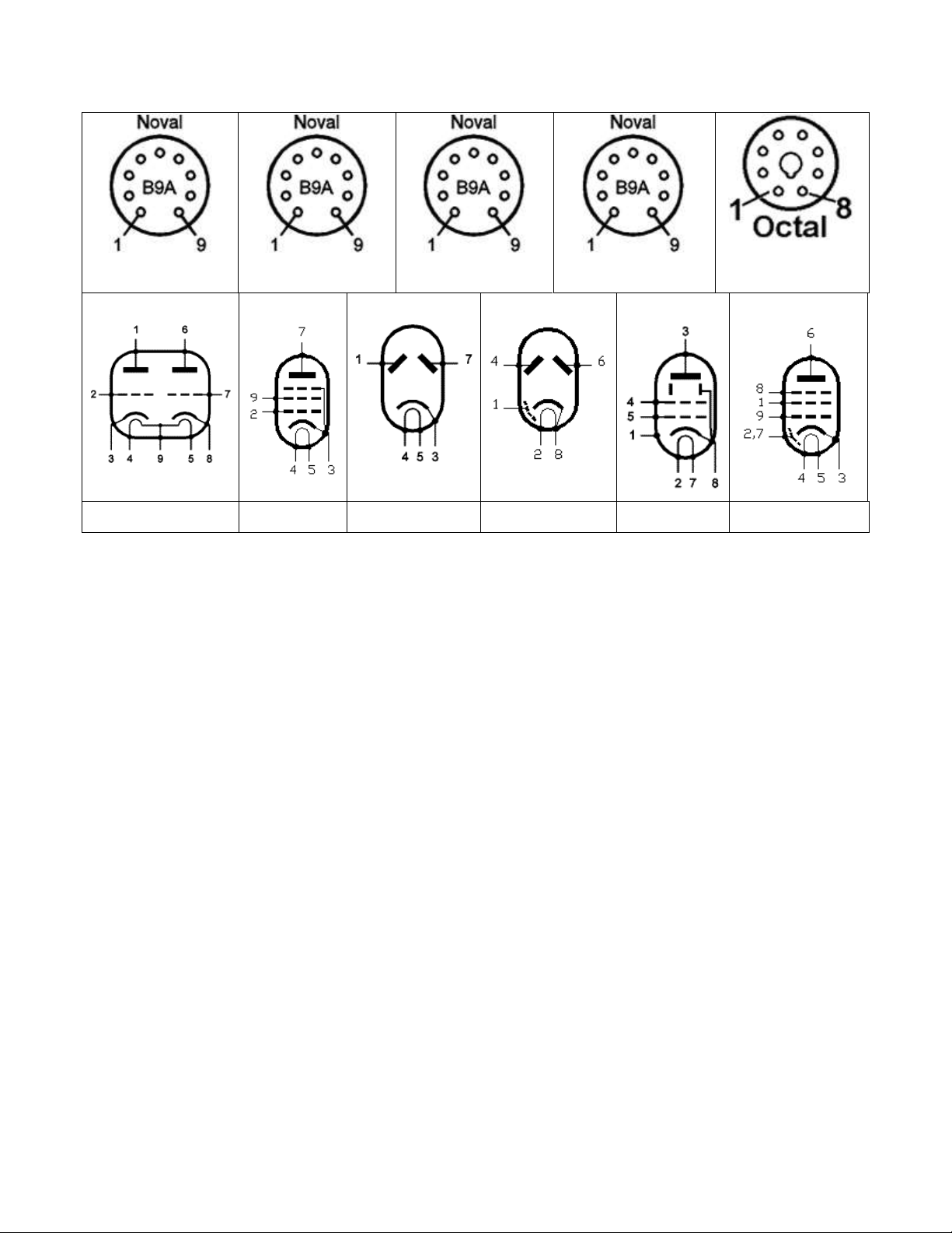
Tube Pin Numbering
The pins on a 9-pin tube socket are numbered 1 to 9 in a clockwise direction when a tube or socket
is viewed from the bottom. Note that there is a gap between pins 1 and 9. The pins on an 8-pin tube
socket are numbered 1 to 8 in a clockwise direction when viewed from the bottom. Note that there
is a gap between pins 1 and 8.
Trinity Amps THOR Builder’s Guide. Version 21.2
Page - 16
12AX7
EL84
6CA4
EF86
GZ34/6V6
12AX7
EL84
6CA4
GZ34
6V6
EF86
The pins on the potentiometers are numbered 1 to 3 from left to right when the shaft is facing
towards you and the pins are at the top.
Tube Designations
There are several different tube numbering systems that you may see on tubes, which generally are a
result of where they were built. Most commonly the numbers contain digits only (e.g. 5751), or are
some combination of numbers and letters (12AX7, ECC83, CV4004). These different numbering
systems may be from the American or British military, or from American or European industrial or
consumer use, and then of course there are many strange exceptions. But to use the notation
commonly seen in the United States, here is the meaning of "12AX7":
12 - the filament voltage
AX - an arbitrary model number
7 - the number of internal elements, including the filament
To make things more complicated, many tubes have letters after the name, such as 6L6WGB,
6L6GC. Sometimes these letters mean functionally nothing (design revisions) and sometimes they
refer to different voltage capabilities of a given type.

Trinity Amps THOR Builder’s Guide. Version 21.2
Page - 17
NORTH AMERICA
EUROPE
12AX7
ECC83
6BQ5
EL84
6CA4
EZ81
5AR4
GZ34
6CA7
EL34
6L6GC
KT66
12AT7
ECC81
12AU7
ECC82
Grounding Scheme
To keep noise to a minimum, the Trinity Amps THOR
layout uses a two point grounding scheme where the power
side of the amp is connected to a single common ground
point (Power Ground), and the pre-amp is connected to
another point on the chassis that is located immediately
beside the input jacks (Pre-Amp Ground).
For grounding these amps, we strongly recommend that
you follow the layout provided. We don’t recommend that
you deviate.
For safety, we use a single Mains Ground point. No other
components may be connected to this point.


Assembly Steps Summary
1. Install Hardware on the Chassis.
2. Wire up the heater wires to the sockets.
3. Install Transformers onto chassis.
4. Wire Power Supply - Mains, Transformer, Rectifier socket, Switches, Pilot light.
5. Assemble the turret board and install on chassis.
6. Connect turret board leads installing off-board parts as you proceed.
7. Wire up Impedance Switch and Output Jacks
8. Wire input jacks and shielded cable.
9. Check Wiring.
10. Follow Start-Up procedure.
Follow Pictorial on Forum –Resource Section –Topic: “THOR Plexi Pictorial Build”

Trinity Amps THOR Builder’s Guide. Version 21.2
Page - 20
1.
Install the Hardware
There are many nuts bolts etc. required. Here are some guidelines.
Part
Qty
Where to use
4-40 X 5/16”
20-25
Holes are tapped so nuts are not required for tube sockets and
IEC connector.
Use KEPS nuts to hold terminal strip at tube locations. Use with
nuts/lock washer to mount the 5 lug terminal strip and 1-#4
power amp screen resistor terminal strip.
6-32 X 3/8”
3
Mount 3 power ground # 6 chassis lugs with KEPS nut. Mount
Capacitor clamp
6-32 X 3/4”
4
Mount turret board to chassis using stand-offs. Screw though
board –spacer and into chassis tapped hole. Use a #6 lock-
washer between the board and screw head.
8-32 X 3/8”
1
Mount Mains ground ONLY. Use any additional lock washers
with #8 chassis lug.
8-32 X 3/8”
2
Mount Output trans. With KEPS lock nuts.
8-32 KEPS nuts
7
4 for power transformer (optionally remove Heyboer PT nuts as
supplied); 2 for Output transformer; and 1 for mains ground
bolt.
10-32 X 1-1/4”
4
Mount chassis to cabinet. Use cage nuts in square holes pressed
into chassis.
Table of contents
Other Trinity Amps Amplifier manuals

Trinity Amps
Trinity Amps Tramp User manual

Trinity Amps
Trinity Amps Tube Effects Loop User manual

Trinity Amps
Trinity Amps OSD User manual

Trinity Amps
Trinity Amps Triton User manual

Trinity Amps
Trinity Amps TriFly User manual

Trinity Amps
Trinity Amps TRIP TOP User manual

Trinity Amps
Trinity Amps TRIWATT User manual

Trinity Amps
Trinity Amps Trinity Tweed Amp User manual


