Electronics Line EL-2635 User manual
Introduction
The EL-2635 is a wireless repeater designed to extend the
range of wireless devices registered to the control system. Up
to four repeaters can be registered to the control system with 32
transmitters registered to each repeater. The repeater is
powered by either 9VAC with a 6V rechargeable backup
battery pack or 12VDC*. Registration and maintenance tests
are performed using a plug-in LCD programming keypad that
provides a comprehensive interface to the repeater.
UL NOTE: Operation with 12VDC power source has not
been evaluated by UL
Installation
1. Register all wireless devices to the control system as explained in the control system installation manual.
2. On the control system, define the detection devices that are intended to transmit via the repeater as follows:
•From the Programming menu, select Devices, Zones [911].
•Select the zone you want to program (1-32).
•From the zone’s sub-menu, select Repeater [#9].
•Select “Use Repeater”.
Note: It is not necessary to define, at the control system, the keypads and keyfobs that are registered to the repeater.
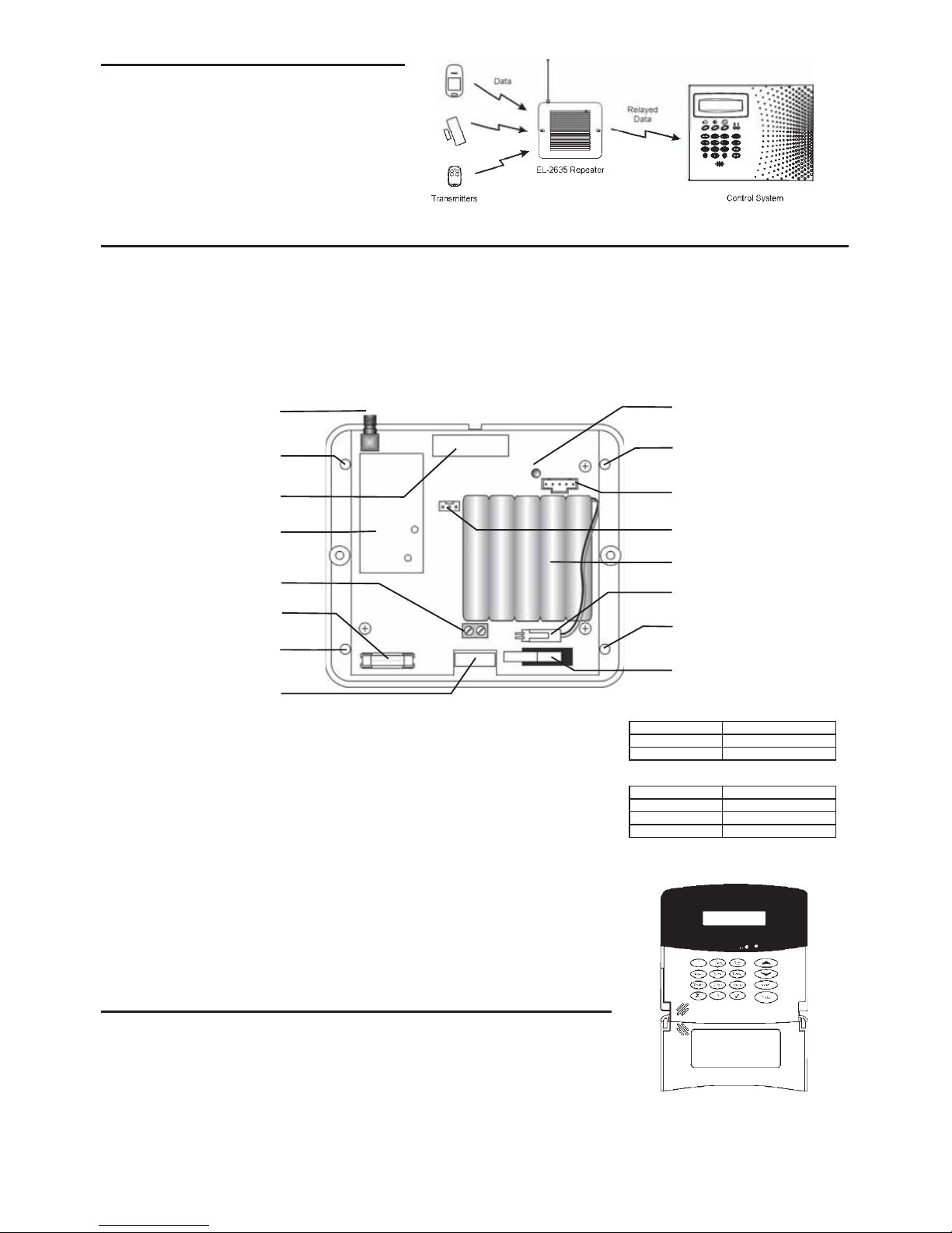
3. Open the EL-2635’s plastic housing. To do so, remove the two cover screws and lift the front cover away from the base.
Figure 2: EL-2635 (cover removed)
4. Connect the antenna provided to the antenna connector.
5. Connect a 9VAC [No. 1332] transformer or 12VDC to the Power input terminal block (polarity is
not important when connecting AC to the terminal block). In North America, plug the
transformer into a 24-hour source of 120VAC that is not controlled by a switch.
All registration and test functions, described in the following sections, are performed from the
LCD programming keypad (ELPN 5200250) shown in Figure 3.
Note: Wait for approx. 20 seconds between applying AC power and connecting the
programming keypad.
6. Connect the programming keypad to the Programming Keypad connector.
Note: The programming keypad (5200250) is not able to operate on battery power only.
7. Test the repeater from the required mounting location before permanently mounting the unit.
8. Connect the backup battery pack to the Battery connector.
9. Mount the base to the wall using four screws and replace the front cover.
When the tamper switch is open, the bi-color LED provides indication regarding repeater transmission and
reception as an aid during the installation procedure – see Table 1. When the tamper switch is closed, the bi-
color LED provides indication regarding power status – see Table 2.
Registering the Repeater to the Control system
For the control system to recognize the repeater, you must register the repeater to the control system.
To register the repeater to the control system:
1. Set the control system to Registration mode as follows:
•From the Programming menu, select Devices, Repeaters [914].
•Select the repeater you want to register (1-4).
•From the repeater’s sub-menu, select Register [#1].
2. Send two Status transmissions from the repeater as follows:
•On the programming keypad, press until 5. STS Transmit appears on the display, press twice.
A
ntenna
Connecto
r
Programming Keypad
Connector
Lowe
r
Mounting
Hole
Upper
Mounting
Hole
Lower
Mounting
Hole
LED Indicator
Receiver
Tamper
Switch
AC Powe
r
Protection Fuse
Uppe
r
Mounting
Hole
Transmitter Flash Programming
Connector
Power Input
Terminals
Wiring
Hole
Figure 1: Typical Single Repeater Application
LED Indication Description
Flashing Green Signal Reception
Flashing Red Signal Transmission
Table 1: LED Indication (Tamper Open)
LED Indication Description
Steady Green AC & Battery OK
Flashing Red AC Loss
Flashing Orange Low Battery
Table 2: LED Indication (Tamper Closed)
Backup
Battery Pack
Battery Connector
Figure 3: LCD
Programming Keypad
3. Confirm registration to the control system as follows:
•When Save? appears on the control system’s LCD display, press .
Note: A sensor should not be registered on more than one repeater or misoperation will result.
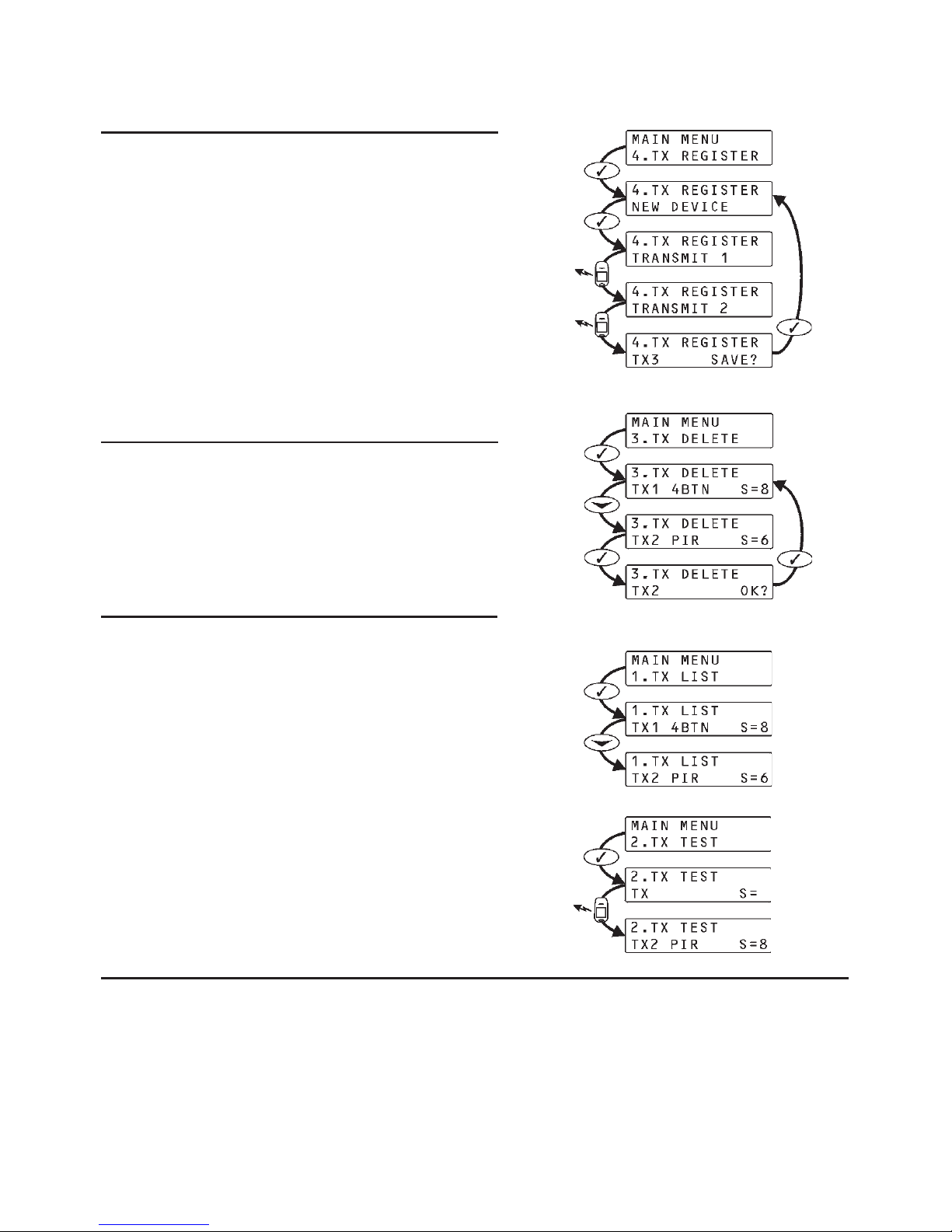
Registering Transmitters to the Repeater
You can register up to 32 transmitters to the EL-2635 repeater.
Note: Do not register the same transmitter to more than one repeater.
To register transmitters to the repeater:
1. On the LCD programming keypad, press until 4. TX Register
appears on the display.
2. Press ; New Device appears on the display.
3. Press again; Transmit 1 appears on the display.
4. Send two transmissions from the device you want to register.
5. When the transmitter number and Save? appear on the display, press
to confirm registration.
Note: The EL-2635 repeater automatically allocates a transmitter
number to each newly registered device. Write this number and
the zone number on the sticker provided with the sensor and
stick it inside the transmitter’s cover for future reference.
6. After you have confirmed registration, the display returns to New
Device. Press to register another device or to exit
Registration mode.
Deleting Registered Transmitters
To delete transmitters from the repeater’s register:
1. On the LCD programming keypad, press until 3. TX Delete
appears on the display.
2. Press ; the first transmitter in the list appears on the display.
3. Use the arrow navigation keys (/) to scroll to the transmitter you
want to delete.
4. Press to select the transmitter.
5. Press again for confirmation; the transmitter is deleted.
6. Select another transmitter to delete or press to exit.
Installer Utilities
The EL-2635 repeater offers two installer utilities that serve as a valuable aid
during installation and maintenance.
TX List
The TX List is a scrollable inventory of all registered transmitters and their last
reported signal strength.
To view the TX list:
1. Press until 1. TX List appears on the display.
2. Press ; the first transmitter in the list is displayed.
3. Use the arrow navigation keys (/) to scroll through the list, press
to exit the list.
TX Test
TX Test is a utility that enables you to identify registered transmitters and test
their signal strength.
To perform a TX test:
1. Press until 2. TX Test appears on the display.
2. Press .
3. Activate a transmitter; the transmitter number, type and signal strength
are displayed, press to exit TX Test mode.
Technical Specifications
Frequency: 868.35MHz, 433.92MHz or 418MHz FM
UL Note: UL has only evaluated operation at 418MHz
Antenna: External Whip
Operating Voltage: 9VAC (No. 1332) or 12VDC
Backup Battery: 6V/850mAh (ELPN BT5757)
(5 x 1.2V Ni-MH rechargeable cells, size AAAL)
Current Consumption: 100mA max. (during transmission)
Number of Transmitters: 32 max.
Tamper Protection: Front Cover (N.C.)
Operating Temperature: 0-60°C (32-140°F)
Dimensions: 123 x 109 x 27mm (4-7/8"W X 4-1/4"H X 1"D)
Figure 6: TX List Procedure
Figure 7: TX Test Procedure
Figure 4: Transmitter Registration Procedure
Figure 5: Delete Transmitter Procedure

Contacting Electronics Line
International Headquarters:
Electronics Line 3000 Ltd.
14 Hachoma St., 75655
Rishon Le Zion, Israel
Tel: (+972-3) 963-7777
Fax: (+972-3) 961-6584
A
ll data is subject to change without prior notice. In no event shall Electronics Line 3000 Ltd.
(EL3K) be liable for an amount in excess of EL3K.’s original selling price of this product, fo
r
any loss or damage whether direct, indirect, incidental, consequential or otherwise arising out
of any failure of the product. Hereby, Electronics Line 3000 Ltd. declares that this transmitter
is in compliance with the essential requirements and other relevant provisions of Directive
1999/5/EC.
All rights reserved
No part of this document may be reproduced in any form without the prior written permission from the publisher
Electronics Line Ltd. 3000 07/2012 5INZI0351E F
This manual suits for next models
1
Other Electronics Line Repeater manuals


