ElectroSmash Time Manipulator User manual
How to Build the Time Manipulator Guitar Pedal.
This document will guide you to build and test your Time Manipulator guitar pedal.
With all the materials on hand, it takes around 3-4 hours to build it. Try not to rush
and take your time. Play your favourite background music and enjoy the fine art of
building your own guitar effects.
We strongly recommend reviewing the entire instructions before starting. It takes 2
minutes to get a global idea of the build and may save you hours of frustration.
This guide aims to build and test the circuit at the same time in a logical order:
placing the components from small to big and testing.
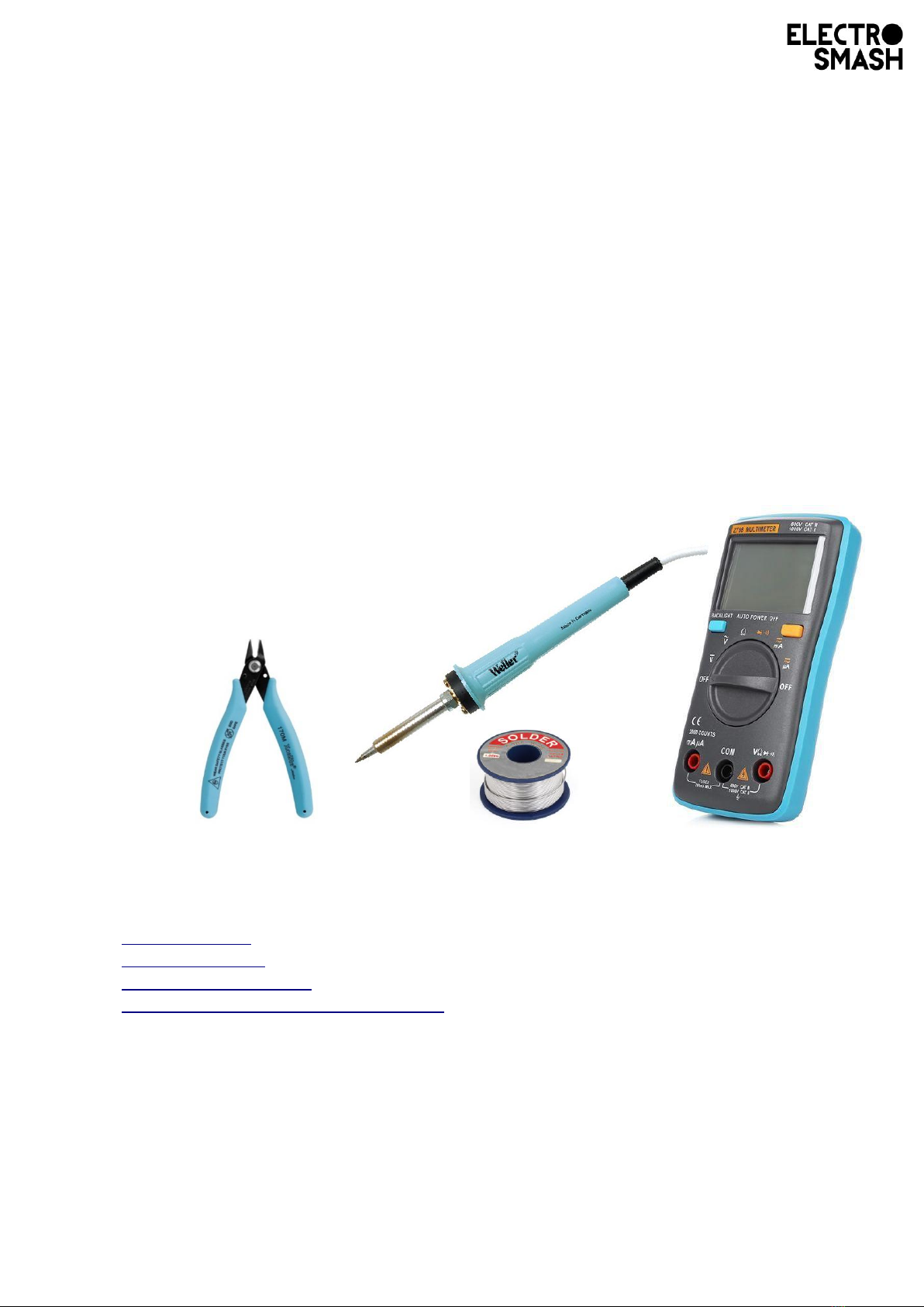
STEP 0 – Prepare the Material:
You would need:
•Soldering iron with a small tip.
•Solder wire.
•Cutting pliers.
•Multimeter.
•Time Manipulator Kit.
Keep in short hand the PCB plan and the Bill of Materials.
•PCB Plan PDF.
•Schematic PDF.
•Bill of Materials PDF.
•1590BBS Fuzz Drilling Stencil PDF.
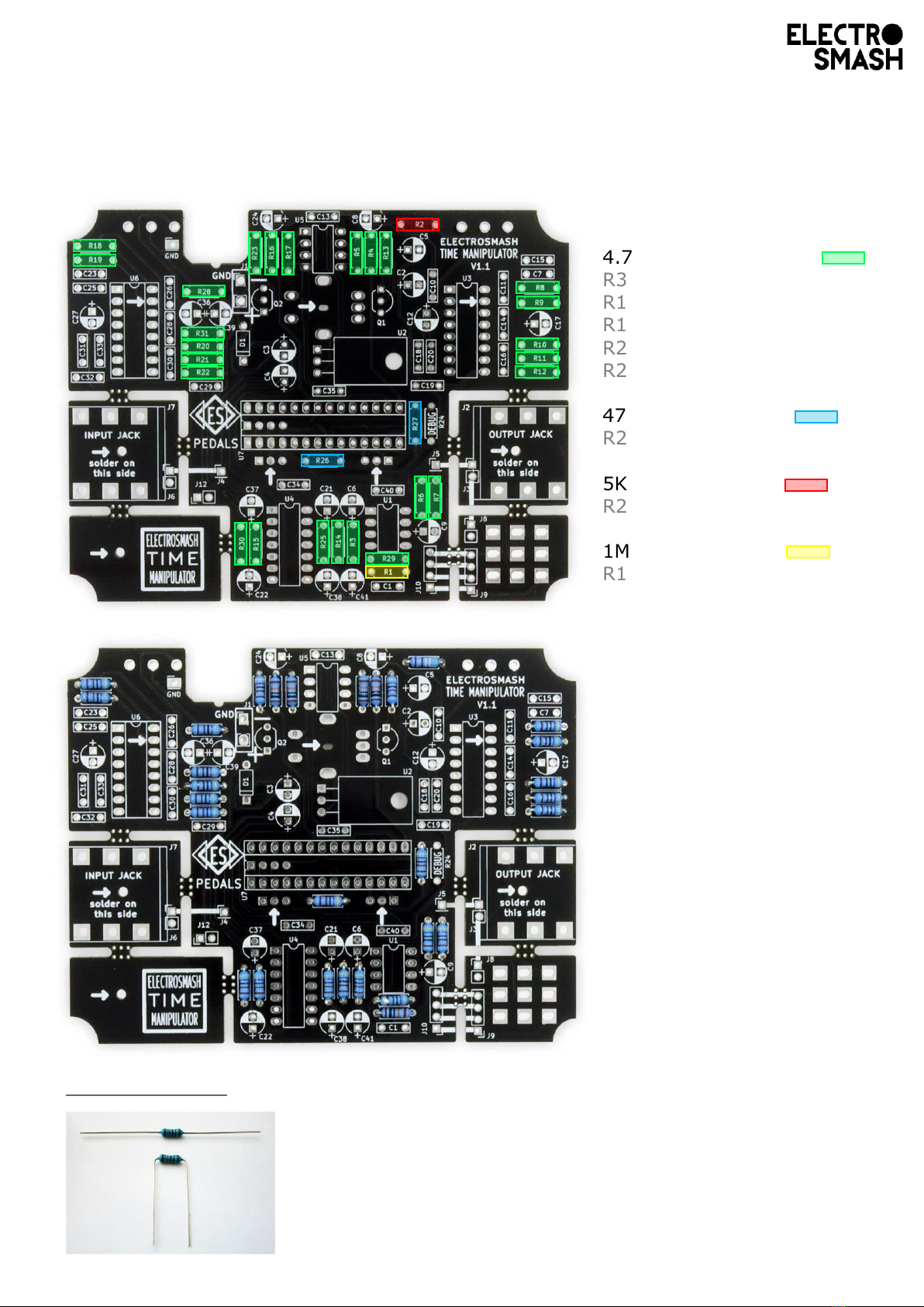
4.7KΩ Resistors (x26):
R3, R4, R5, R6, R7, R8, R9,
R10, R11, R12, R13, R14,
R15, R16, R17, R18, R19,
R20, R21, R22, R23, R25,
R28, R29, R30, R31
470Ω Resistor (x2):
R26, R27
5KΩ Resistor (x1):
R2
1MΩ Resistor (x1):
R1
STEP 1 – Soldering Resistors:
There are 30 resistors to be placed.
Tips before soldering:
Bend the resistor leads as close to the body as possible, fit them in the
footprint and once soldered cut the excess of lead as short as possible to
avoid short circuits.
Once the legs are cut, touch again with the soldering iron the joint to secure
the connection.

100nF capacitors (x15):
C1, C10, C13, C16, C18, C19,
C20, C25, C30, C31, C32,
C33, C34, C35, C40
3nF caps (x4):
C11, C14, C26, C28
6.8nF caps (x4):
C7, C15, C23, C29
STEP 2 – Soldering Small Caps:
There are 23 ceramic capacitors to be placed.
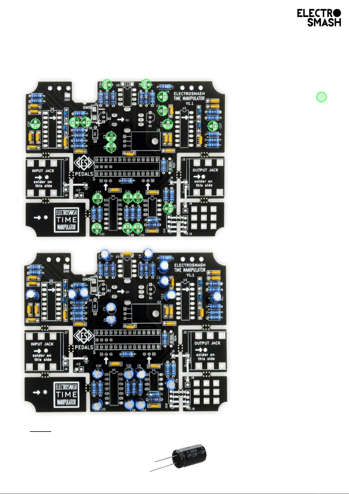
47uF capacitors (x18):
C2, C3, C4, C5, C6, C8, C9,
C12, C17, C21, C22, C24,
C27, C36, C37, C38, C39,
C41
Long lead, positive +
Short lead, negative -
Line marked on the negative side
STEP 3 – Soldering Big Caps:
There are 18 electrolytic capacitors to be placed.
*Note: The electrolytic caps have polarity, insert the long lead into the hole labeled
with “+”
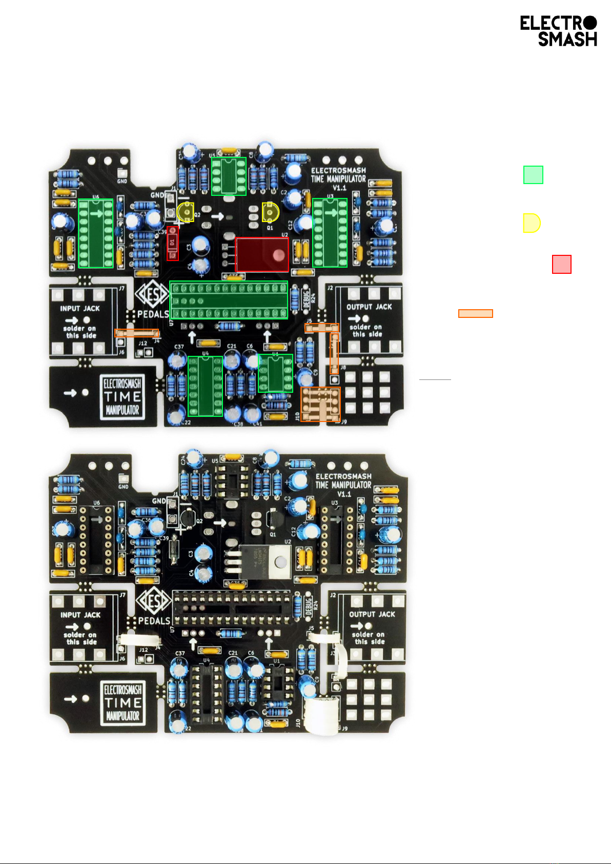
IC sockets (x6):
U1, U3, U4, U5, U6, U7
Transistors (x2):
Q1, Q2
Regulator and Diode
D1, U2
Wires
J4, J5, J8, J9
Note: U1 is preferred to be a
TL072 and U5 a MCP6002
although you can use a
MCP6002 for both U1 and U5.
STEP 4 – Soldering Small Components:
There are 14 small components to be placed.
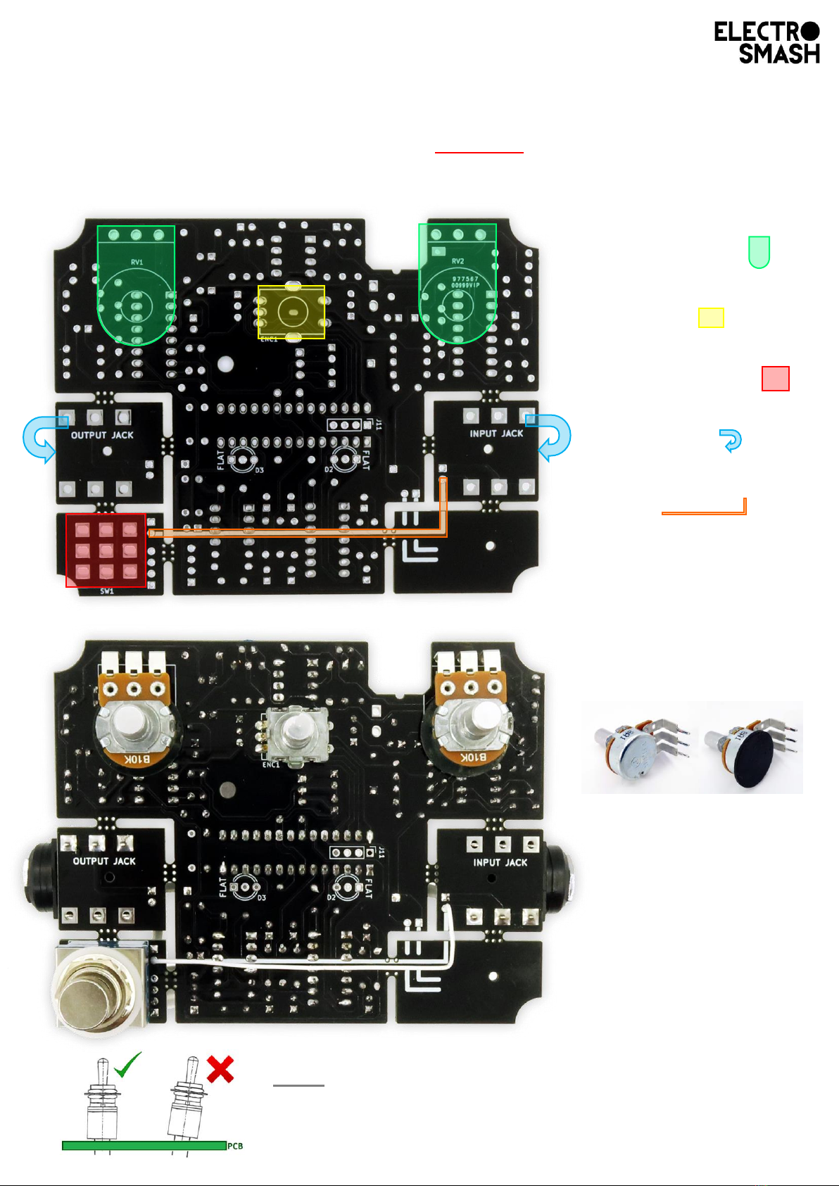
Potentiometers (x2):
RV1, RV2
Encoder (x1):
ENC1
Footswitch 3PDT (x1)
SW1
Audio Jacks (x2)
J2, J7 (on the other side)
Wire (x1)
J6 to J8
*
*
Isolate the bottom part of
the potentiometer with a
rubber disc:
The potentiometer rests
on top of the PCB, so the
rubber will avoid short-
circuits.
Note: Big components tent to tilt when soldered. Make sure
they are straight: A good idea is to solder only one pin and
once you are sure that it is perpendicular, solder the rest of
the pins.
STEP 5 – Soldering Big Components:
There are 5 big components to be placed. Make sure that you solder them on the
correct side of the board (top or bottom).
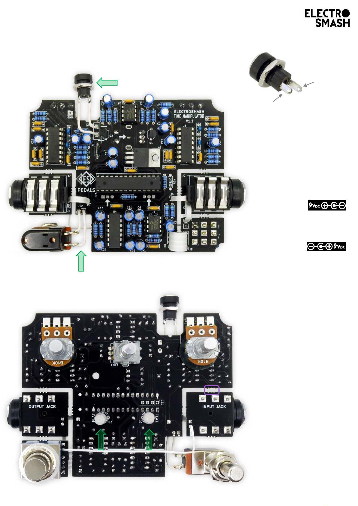
Short leg
negative -
Long leg
positive +
1
2
1
Using 2 short wires (3cm)
connect the 2.1mm power
jack connector to the – and
+ pads of the board.
Make sure that the short
lead goes to – and the long
lead to + this will make the
power supply centre
negative (boss style).
If you want to use a
“normal” 9 to 12Vdc centre
positive adapter, just invert
the connection.
You will need to solder this
power jack again when
boxing the pedal, so don’t
lose time make the
soldering perfect just yet.
Using two short wires (3cm)
connect the momentary
footswitch to the connector
J12.
3
3
3
Put the 2 LEDs through the
holes, they will stay in place
without the need of
soldering.
The LEDs have to be soldered
once the PCB goes into the
enclosure, so
DON’T SOLDER THE LEDs
YET.
*
*
It is better to break the
mousebites (separate the
PCB) later, in Step 10
STEP 6 – Finish the Assembly:
Top side:
Bottom side:

STEP 7 – Checking the Board:
The first thing to check is the power supply:
•Do not place any IC, keep the sockets empty.
•Connect the +9V (centre positive) power supply.
With a multimeter, measure the highlighted points. Make sure that the bias voltages
reach every chip and they are correct.
Note: These 2.5V are generated by the PT2399 chips, so you will not see it yet. Once you measure
that all the voltages are OK, place the PT2399s and you will see the 2.5V.
0V
+5V
0V
+9V
+4.5V
+5V
0V
+5V
+5V
+2.5V
0V
+9V
+9V
+9V
0V
+5V
0V
+5V
0V
0V
*
+2.5V
*
*
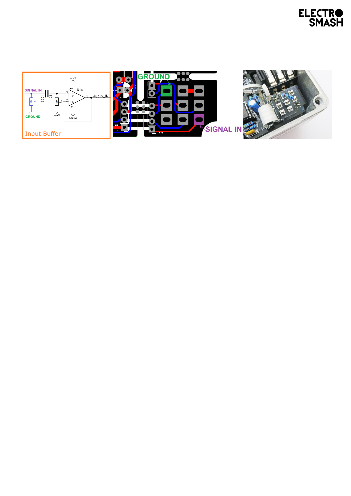
Reduce POP mod:
In order to reduce the pop sounds when the pedal is engaged, an optional 1M to 2.2M pull down
resistor could be placed at the input of the circuit:
Note: This optional resistor will not affect the sound performance of the pedal. It will only attenuate
the engaging clicks of the footswitch.
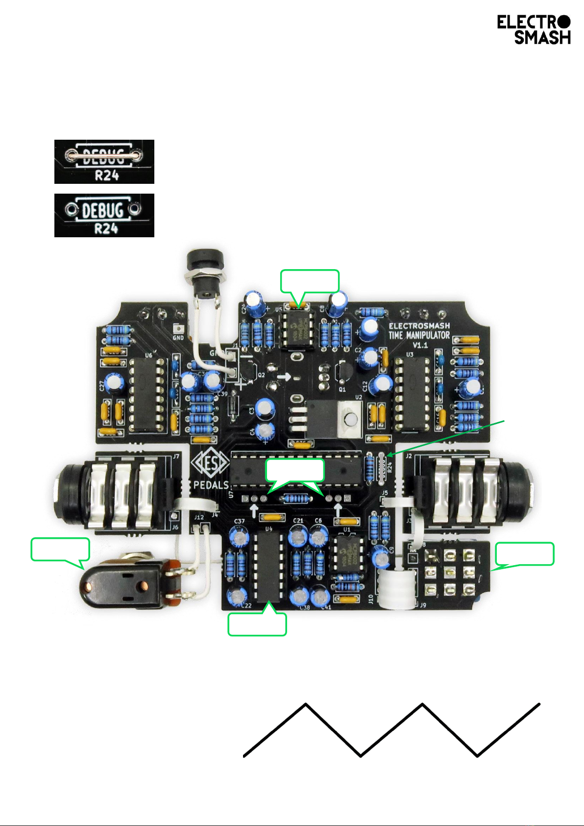
Enter DEBUG mode: Just use a wire or a resistor leg to connect
the R24 DEBUG pads. The pedal will go into debug mode.
Normal mode: When you finish doing the debug tests, just de-
solder or cut the wire across R24. The pedal will stay in normal
mode. This is the mode you will use 99.9% of the time.
STEP 8 – Going into DEBUG MODE:
The debugging mode is designed to check every system in the board, it will allow you
to make a series of tests and verify the build.
Debug Mode Tests:
•Test1: measure with a multimeter the U5 pins 2 and 6, they should be ramping
up and down from 0 to 2.4 volts.
Test1
Test2
Test3
Test4
Test4
Test4
Make sure
you are in
DEBUG
mode
0V
+2.4V
4s
2s
6s
8s
+2.4V
+2.4V

J7-Input
J2-Output
•Test2: measure with a multimeter U4 pins 5, 6, 12 and 13, they should be
going ON(+5V) and OFF(0V) every 2 seconds:
•Test3: While pushing the tap footswitch (connected to J12), measure again U4
pins 5, 6, 12 and 13 they should be going ON(+5V) and OFF(0V) every 1 second:
•Test4: When in debugging mode, the LEDs should light in loop:
GREEN - RED – OFF
oIf you activate the pedal pushing the 3PDT footswitch SW1, the LEDs will
do the loop at double the speed.
NOTE: Once you finish, disconnect the R24 DEBUG wire, so the pedal can do to
normal mode.
STEP 9 – Check the Pedal:
At this point, you are ready to use the pedal. It is designed to be checked before
being boxed, so makes everything easier to fix and mod.
Have a look at the Time Manipulator Instructions if you have any question about the
functionality. At this point, you can also easily reprogram the microcontroller if you
want to experiment with sounds.
Note: The board is upside down, so the amp and guitar connect to opposite sides (see below):
0V
+5V
+5V
0V
1s
2s
3s
4s
2s
4s
6s
8s

STEP 10 – Boxing the Electronics:
The bare PCB can be used to mark the holes at the exact point:
The arrows on the PCB are showing where to mark the 7 holes ( ). They are small
so you would need a thin pencil to go through the board.
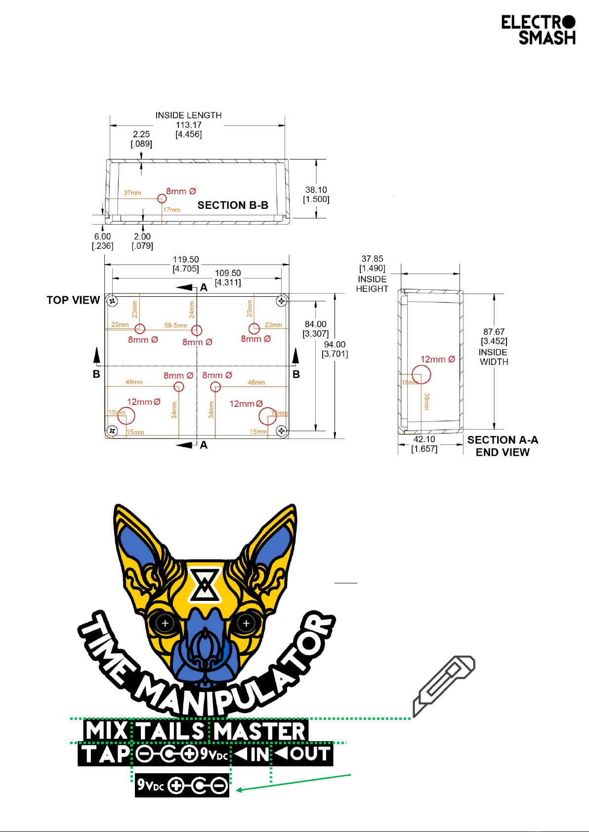
This is the Hammond 1590BBS drill stencil.
Use a cutter to separate the stickers:
Note: At the last page of this document,
you can see how the stickers are placed.
Boss style power supply sticker

Boxing:
•Make sure that all the soldered parts have their legs cut as close as possible
to the PCB.
•Don’t force the parts into the holes –be gentle- , they are designed to be tight
but not forced. If they seem to be stuck, remove the electronics and start
again.
•The best way to enclose the board is to try to fit all the parts through their
holes at the same time (not simply inserting one jack after the other).
Separate the
stickers and place
them.
Be careful centring the cat eyes
with the 2 holes, you can look from
the inside of the box in a bright
room.
Open the round eyes on the sticker
with a cutter and place the 5mm
LED holders.

Time Manipulator Finished:
The LEDs are not soldered yet, so you can move
them up/down, left/right and once they are in
position solder them.
You can separate
the PCB with
your hands or
use pair of small
pliers to do it.
Don’t forget the nut before soldering
Other ElectroSmash Music Pedal manuals


