ELEFUN SMC Sea Fury User manual

Instruction Manual
Wingspan : 1420mm
Length : 1320mm
Weight : 3300g - 4000g
Radio : 5 servo + 1 servo retract / 6 channel
Engine : 61-75 two stroke
g

Instruction Manual STINSON - EP
1
Instruction Manual SEA FURY
KIT CONTENTS: We have organized the parts as they come out of the box for better identification
during assembly. We recommend that you regroup the parts in the same manner. This will ensure you
have all of parts required before you begin assembly.
MAIN GEAR ASSEMBLY
. (8) 2mm x 10mm screws
. (2) 55mm diameter wheels
. (2) Metal rod 1.7mm x 300mm
. (2) Plastic cover
. (4) Collar
. (2) Retract gear
. (2) Metal clevises M2
. (2) Silicone tube
. (2) Metal connector
TAIL GEAR ASSEMBLY
. (1) Tail gear
. (1) 25mm diameter wheel
. (2) Wheel collar
. (2) Plastic clasp
. (2) 2mm x 16mm screws
ELEVATOR CONTROL SYSTEM
. (2) Control horn
. (2) 3mm x 30mm screw
. (2) Nylon horn
. (2) Metal clevis M2
. (2) Silicon tube
. (1) Nylon snap keepper
. (1) Domino connector
. (1) Metal rod 1.7mm x 100mm
RUDDER CONTROL SYSTEM
. (1) Control horn
. (1) 3mm x 45mm screw
. (1) Nylon horn
. (1) Metal clevis M2
. (1) Silicon tube
. (1) Nylon snap keepper
THROTTLE CONTROL SYSTEM
. (1) 1.3mm x 500mm wire
. (1) 3.5mm x 350mm nylon pushrod housing
. (1) Metal connector
AILERON CONTROL SYSTEM
. (2) Control horn
. (2) 3mm x 45mm screw
. (2) Nylon horn
. (2) Metal clevis M2
. (2) Silicon tube
. (2) Nylon snap keepper
. (4) Metal rod 1.7mm x 180mm
MOTOR MOUNT ASSEMBLY
. (1) Engine mount
. (4) 4mm x 25mm screws
. (4) Flat Washer
. (4) Lock Washer
. (8) Nut
. (4) 4mm x 30mm screws
FUEL TANK
. (1) Nylon fuel tank
. (1) Metal clunk
. (1) Pre - assembled stopper w / 3 tube
MISCELLANEOUS ITEMS
. (1) Dihedral
. (1) Door of wheel cover
. (2) Wing screw
. (2) Plastic plate
. (4) 2,6mm x 10mm screws
. (3) Metal rod 1.7mm x 800mm
. (1) Wooden plate
. (2) 25mm x 400 gray tape
. (1) Spinner
. (1) Plastic engine cover
. (1) Wooden circle
. (4) Block of wood
. (1) Decal
. (1) Cowling
KIT CONTENTS

Instruction Manual SEA FURY
2
1 2
3 4
5 6
7 8
Remove the covering from the top of the wing. Remove the covering from the aileron servo box (at the
bottom of the wing).
Insert the thread into the wing.
Tape the servo lead into the end of the thread.
Pull the servo lead out. Using the masking tape, tape the servo lead onto the top of
the wing.
Install the aileron servo. The aileron control horn and linkages.
1
1Installing the aileron servos and linkage
10
15
13 14
12
9
11
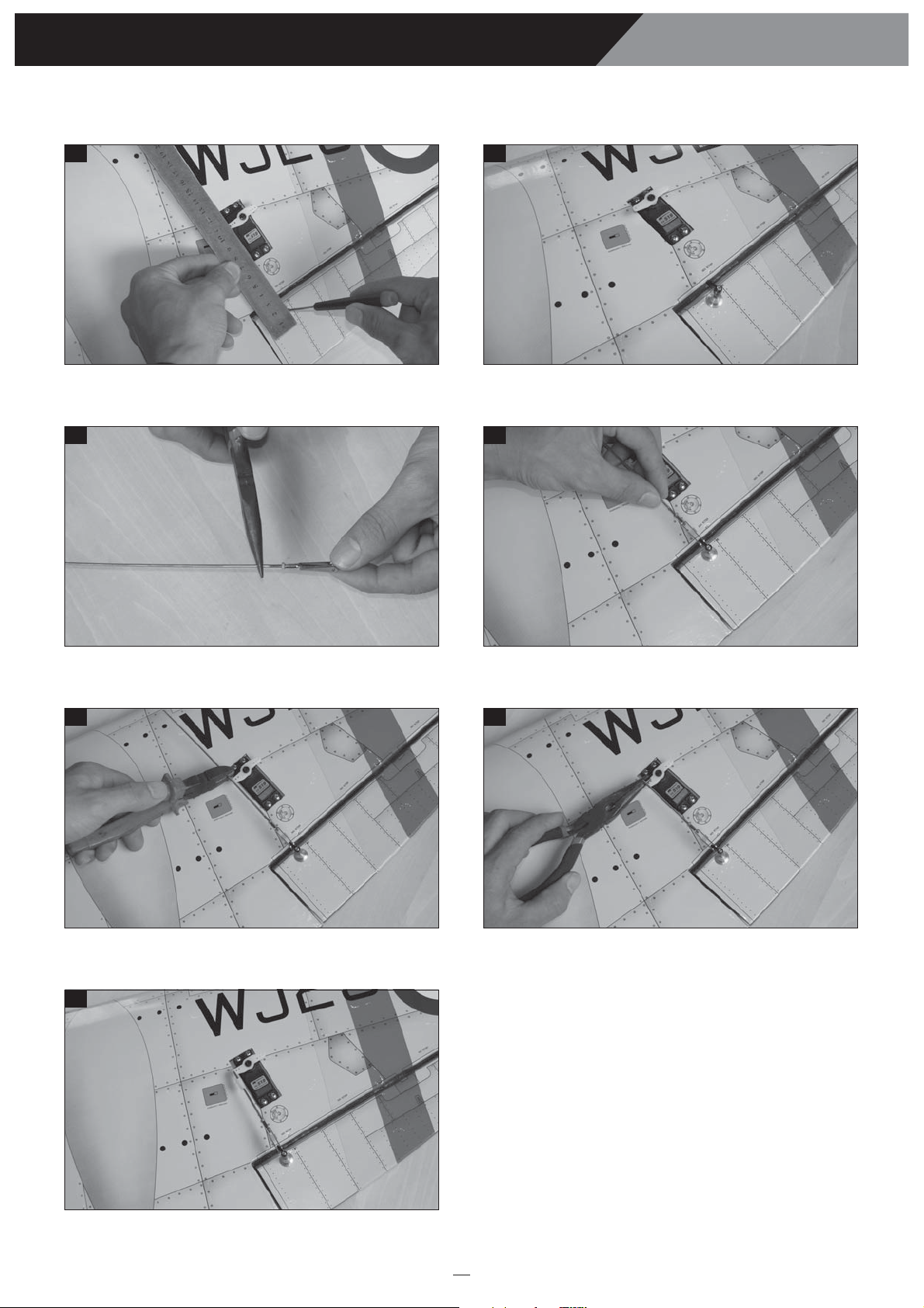
Mark the holes from the control horn onto the bottom of
the aileron.
Install the control horn onto the aileron.
Install the clevis to the aileron pushrod. Insert the clevis into the control horn.
Cut away the aileron pushrod. Bend “L” the aileron pushrod.
Attach the nylon clasp to the aileron servo arm.
3
Instruction Manual SEA FURY

Instruction Manual SEA FURY
4
16 17
18 19
20 21
22 23
Draw a center line. Remove the covering from the rear of the wing.
Glue the wing joiner to the wing, using the epoxy glue. Apply the epoxy into the wing section.
Glue the wing by epoxy. Apply the trim tape to the center section on the top and the
bottom of the wing where they join.
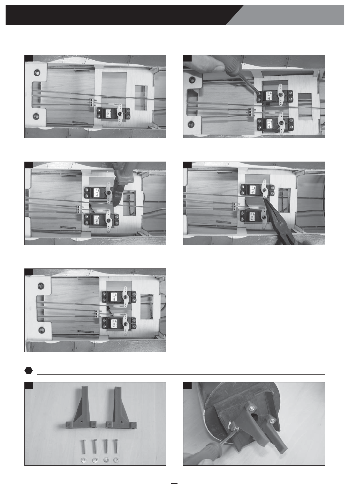
Install the gear servo into the servo tray. One set of the landing gear.
1
2Joining the wing halves
1
3Installing the landing gear
Center line
Instruction Manual SEA FURY
5
24 25
26 27
28 29
30 31
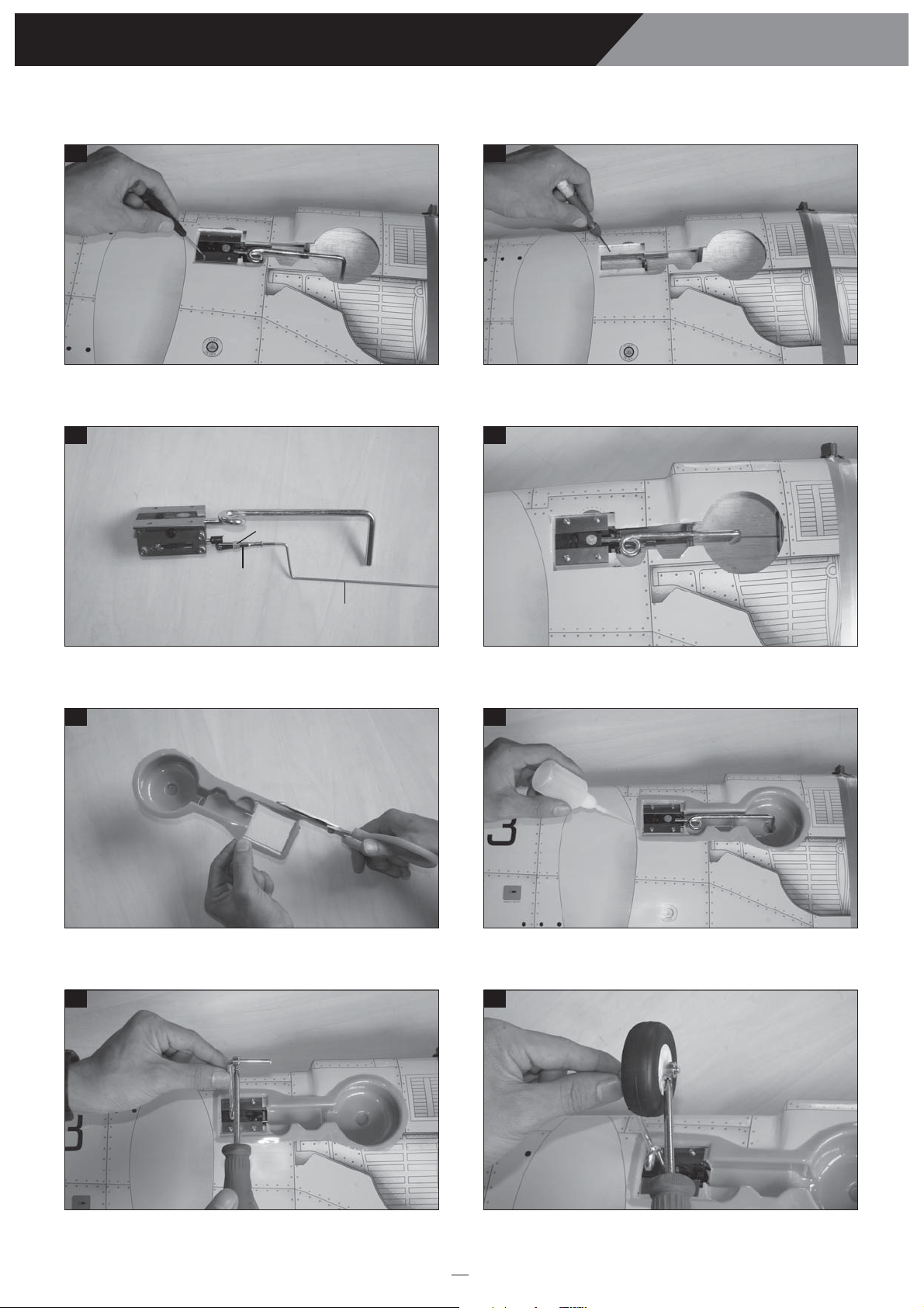
Insert the landing gear into the block and mark four holes
onto the block.
Take out the landing gear and drill four holes into the block.
Attach the metal rod to the landing gear. Install and secure the landing gear into the block.
Prepare the plastic part. Glue the plastic part by C.A glue.
Install the collar into the gear. Install the wheel into the gear.
Metal clevis
Silicone
Metal Pushrod

Instruction Manual SEA FURY
6
32 33
Install two metal connector to the servo arm of the gear servo. Install the servo arm and attach two rods to the metal
connector.
Close position
Open position

Instruction Manual SEA FURY
7
34 35
36 37
38
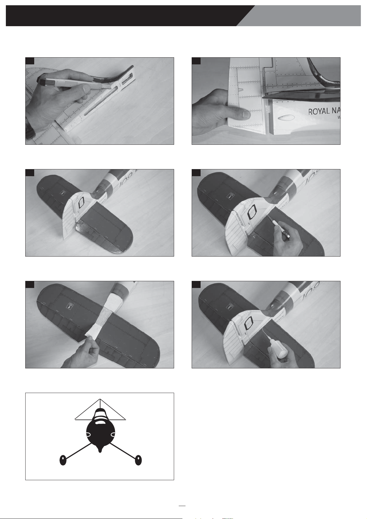
Make a center line onto the horizontal. Remove the covering from the rear of the fuselage.
Make the slot from the fuselage for rudder hinge. Attach the horizontal to the fuselage and check it.
39 40
Remove the covering from the bottom of the horizontal. Glue the horizontal into the fuselage by epoxy.
Check the horizontal and the wing as shows. Mark the shape of the fuselage onto the bottom of the
horizontal.
1
4Installing the horizontal stabilizer and the vertical stabilizer
Instruction Manual SEA FURY
8
41 42
43 44
45 46
Remove the covering from the rear of the vertical. Insert the hinge into the slot.
Attach the horizontal and the vertical to the fuselage. Mark the shape of the vertical onto the top of the horizontal.
Remove the covering from the top of the horizontal. Glue the vertical into the fuselage by epoxy and also glue the
hinge of rudder.
Check the vertical before it dry.
a1 a2
a1 = a2

Instruction Manual SEA FURY
9
47 48
49 50
51 52
The control horn. Install the control horn onto the elevator.
Make the same way for the second control horn. Remove the covering from the slot.
Attach the clevis to the elevator pushrod. Insert the silicone tube into the clevis.
53 54
Insert the elevator pushrod into the fuselage. Attach the clevis to the control horn.
1
5Installing the elevator and rudder pushrod
1
6Installing the tail gear
Instruction Manual SEA FURY
10
55 56
57 58
59
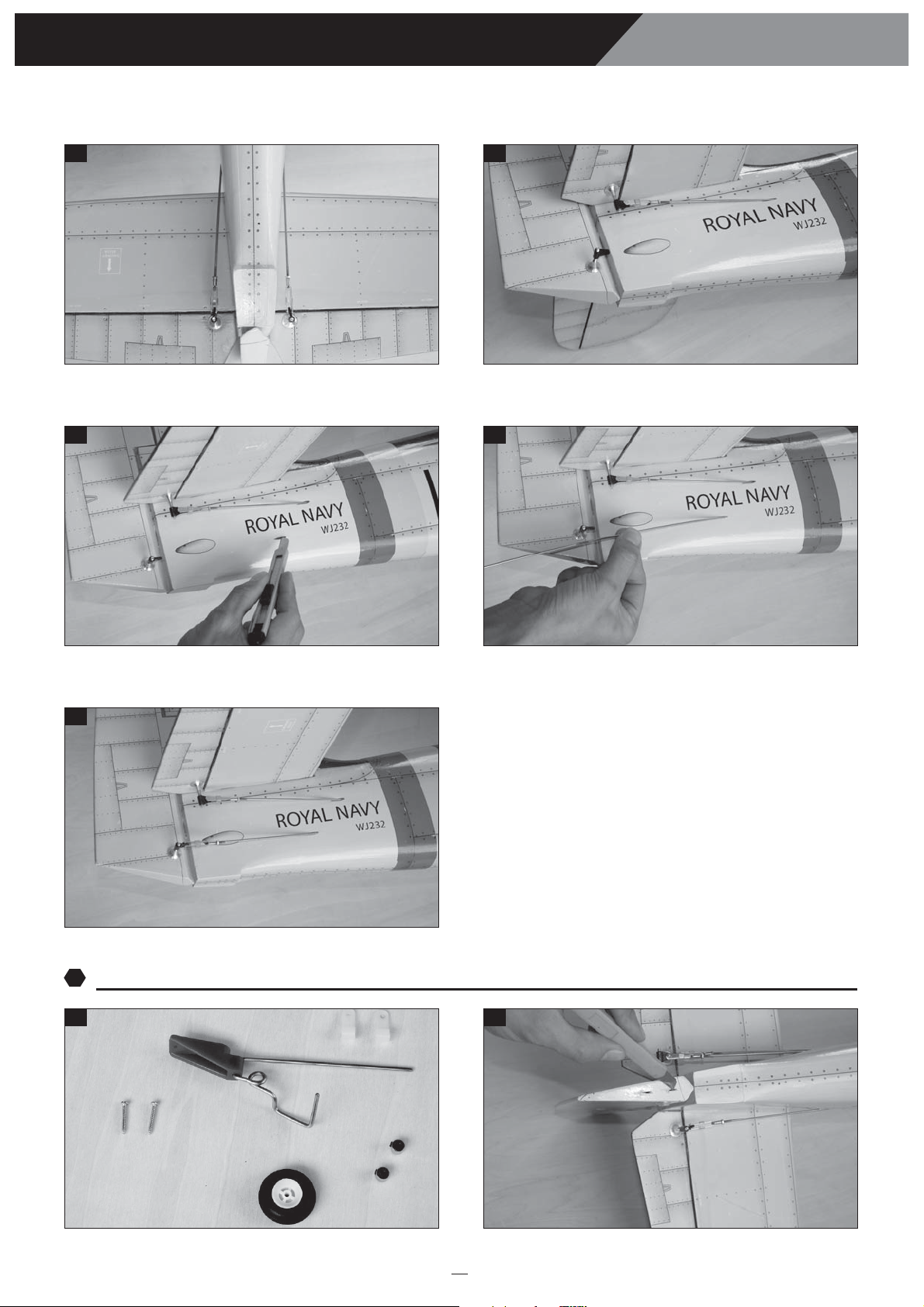
Make the same way for the second elevator pushrod. Install control horn onto the rudder.
Remove the covering from the slot. Insert the rudder pushrod into the fuselage.
60 61
The tail gear. Make the slot from the bottom of the rudder.
Attach the clevis to the control horn.

Instruction Manual SEA FURY
11
62 63
64 65
66 67
68 69
Install the two nylon clasp onto the bottom of the rudder. Glue the two nylon clasp C.A glue.
Install the wheel and the collar into the tail gear. Install the tail gear into the fuselage and secure it.
Install the elevator servo and secure it. Cut away the elevator pushrod.
Prepare the metal connector. Secure the elevator pushrod.
1
7Installing the servo of the elevator and rudder
Instruction Manual SEA FURY
12
70 71
72 73
74
Attach the nylon clasp. Install the rudder servo and secure it.
Cut away the rudder pushrod.
Bend “L” the rudder pushrod.
75 76
The engine mount.
Install the engine mount.
Attach the nylon clasp.
1
8Installing the fuel tank and the engine
Instruction Manual SEA FURY
13
77 78
79 80
81 82
83 84
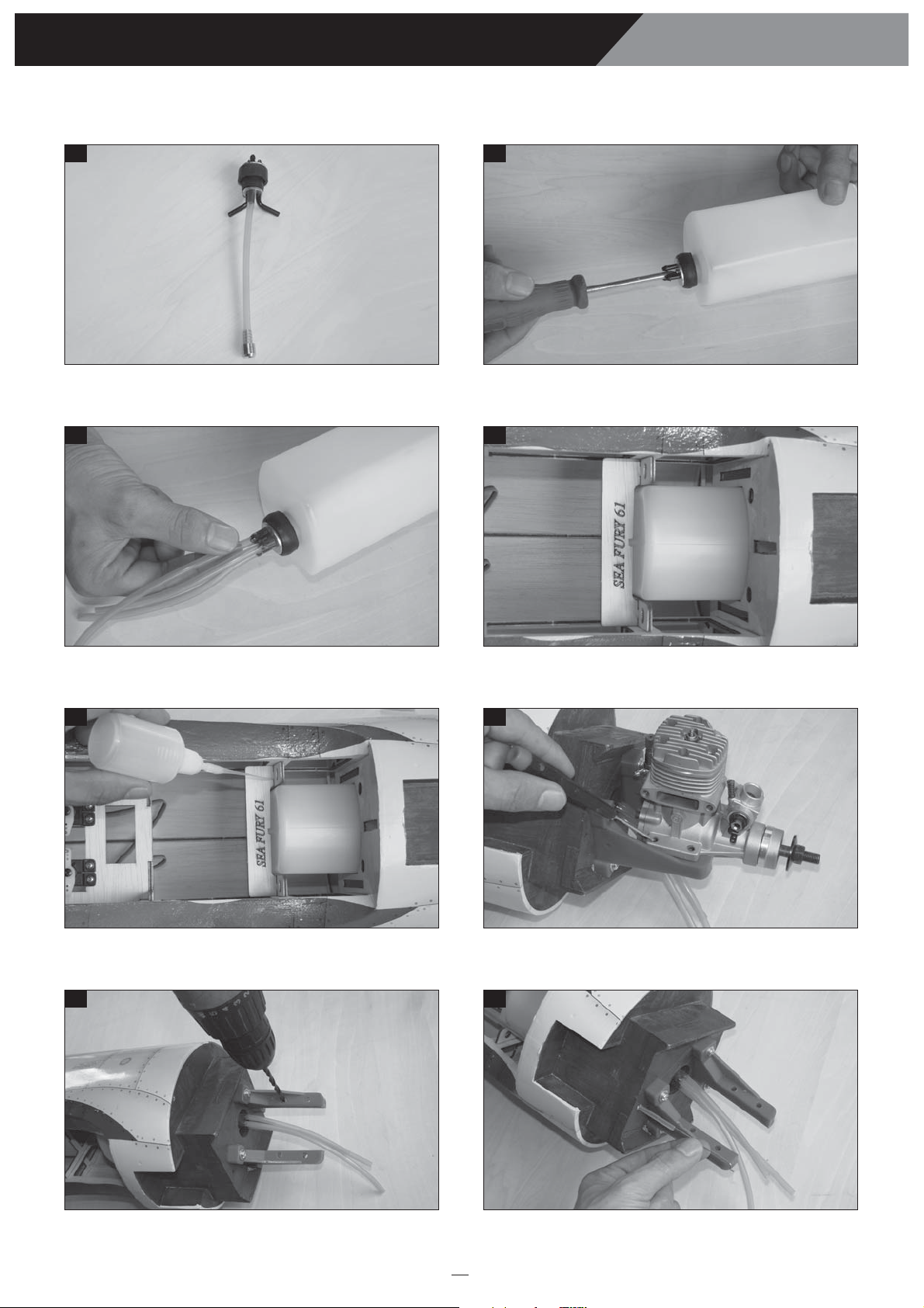
Prepare the stopper for the tank. Secure the stopper.
Install the silicone tube of the tank (not included).
Slide the fuel tank to the fuselage.
Secure the fuel tank by C.A glue. Attach the engine to the engine mount and mark four holes.
Drill four holes onto the engine mount. Install the throttle rod.

Instruction Manual SEA FURY
14
85 86
87 88
89 90
91 92
Glue the nylon housing. Attach the throttle rod to the arm of the carburator.
Install the engine and secure it. Secure the muffler.
Install the throttle servo. Install the metal connector to the servo arm.
Secure the throttle rod. Cut away the throttle rod.

Instruction Manual SEA FURY
15
93 94
95
96 97
Place the switch to the fuselage. Install the switch.
Install the receiver and battery.
Glue the block of wood to the plastic cover. Glue the plastic cover to the cowl.
98 99
Prepare the cowl. Install the cowl.
1
9Installing the switch, receiver and battery
1
10 Install the plastic engine cover
Receiver
Battery
Instruction Manual SEA FURY
16
100 101
102
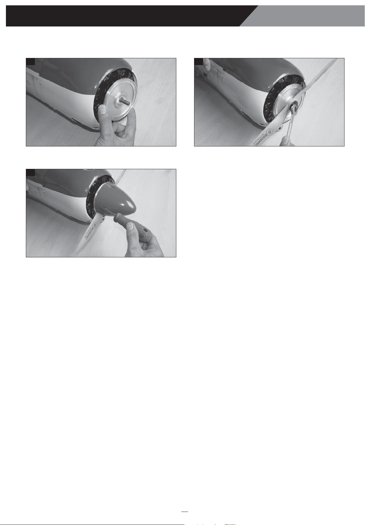
Insert the plate of the spinner. Install the propeller.
Install the propeller.

BALANCING
1. It is critical that your airplane be balanced correctly.
Improper balance will cause your plane to lose
control and crash.
THE CENTER OF GRAVITY IS LOCATED 105mm
BACK FROM THE LEADING EDGE OF THE WING,
AT THE FUSELAGE.
2. Mount the wing to the fuselage. Using a couple of
pieces of masking tape, place them on the top side of
the wing 105mm back from the leading edge, at the
fuselage sides.
3. Turn the airplane upside down. Place your fingers on
the masking tape and carefully lift the plane .
4. If the nose of the plane falls, the plane is heavy nose.
To correct this first move the battery pack further
back in the fuselage. If this is not possible or does not
correct it, stick small amounts of lead weight on the
fuselage under the horizontal stabilizer. If the tail of
the plane falls, the plane is tail heavy. To correct this,
move the battery and receiver forward or if this is not
possible, stick weight into the firewall. When balanced
correctly, the airplane should sit level or slightly nose
down when you lift it up with your fingers.
LATERAL BALANCE
After you have balanced a plane on the C.G. You
should laterally balance it. Doing this will help the
airplane track straighter
CONTROL THROWS
1. We highly recommend setting up a plane using the
control throws listed.
2. The control throws should be measured at the widest
point of each control surface.
3. Check to be sure the control surfaces move in the
correct directions.
1. Turn the airplane upside down. Attach one loop of
heavy string to the engine crankshaft and one to the
tail wheel wire. With the wings level, carefully lift
the airplane by the string. This may require two
people to make it easier.
2. If one side of the wing fall, that side is heavier than
the opposite. Add small amounts of lead weight to
the bottom side of the lighter wing half's wing tip.
Follow this procedure until the wing stays level
when you lift the airplane.
105mm
Ailerons : 12mm up 12mm down
Elevator : 12mm up 12mm down
Rudder : 25mm right 25mm left
Elevator Control
Aileron Control
12mm
12mm
Rudder Control
25mm
25mm
12mm
12mm
FLIGHT PREPARATION PRE FLIGHT CHECK
1. Completely charge your transmitter and receiver
batteries before your first day of flying.
2. Check every bolt and every glue joint in your plane
to ensure that everything is tight and well bonded.
3. Double check the balance of the airplane
4. Check the control surface
5. Check the receiver antenna . It should be fully
extended and not coiled up inside the fuselage.
6. Properly balance the propeller.
17
Instruction Manual SEA FURY

I/C FLIGHT GUIDELINES
Made in Vietnam
When ready to fly, first extend the
transmitter aerial.
Operate the control sticks on the
transmitter and check that the control
surfaces move freely and in the
CORRECT directions. ALWAYS land the model INTO the
wind, this ensures that the model lands
at the slowest possible speed.
Switch on the transmitter.
Switch off the transmitter.
Check that the transmitter batteries
have adequate power.
Switch off the receiver.
Switch on the receiver. ALWAYS take off into the wind.
Check that the wings are correctly
fitted to the fuselage. If the model does not respond correctly
to the controls, land it as soon as
possible and correct the fault.
Empty the fuel tank after flying, fuel left
in the tank can cause corrosion and
lead to engine problems.
Instruction Manual SEA FURY
Table of contents
Other ELEFUN Toy manuals


