Elekta Neuromag NM21283A User manual

Sensor Tuner
User’s Guide
Software Version 3.0 for
Elekta Neuromag
March 2005
NM21283A-A
This document contains copyrighted and possibly confidential information and is intended for the exclusive use of
customers having Neuromag products and authorized representatives of Elekta Neuromag Oy. Disclosure to others or
other use is strictly prohibited without the express written authorization of Elekta Neuromag Oy.
Elekta Neuromag Oy reserves the right to make changes in the specifications or data shown herein at any time with-
out notice or obligation.
Elekta Neuromag Oy makes no warranty of any kind with regard to this document and the related software, including
but not limited to, the implied warranties of merchantability and fitness for a particular purpose. Elekta Neuromag Oy
shall not be liable for errors contained herein or direct, indirect, incidental or consequential damages in connection
with the furnishing, performance, or use of this material and software.
Elekta Neuromag, Vectorview and Neuromag System are trade marks of Elekta Neuromag Oy, UNIX is a trademark
of UNIX System Laboratories, Inc., and Motif is a trademark of Open Software Foundation, Inc.
Editor: Matti Kajola
© 2001-2005 Elekta Neuromag Oy. All rights reserved.
Printed in Finland.
Printing History Neuromag p/n Software Date
1st edition NM21283A tune_vv 3.0.x 2001-12-27
2st edition NM21283A-A tune_vv 3.0.x 2005-03-13
0537

NM21283A-A i
Contents
Introduction 1
Part 1 Basic Usage
Chapter 1 User interface basics 5
1.1 Using menus . . . . . . . . . . . . . . . . . . . . . . . . . . . . . . . . . . . . . . . 5
1.2 Using text fields . . . . . . . . . . . . . . . . . . . . . . . . . . . . . . . . . . . . 5
1.3 Using file selection boxes . . . . . . . . . . . . . . . . . . . . . . . . . . . . 6
Chapter 2 Getting started 9
2.1 Beginning a session . . . . . . . . . . . . . . . . . . . . . . . . . . . . . . . . . 9
2.2 Using online HELP . . . . . . . . . . . . . . . . . . . . . . . . . . . . . . . . . 10
2.3 Ending a session . . . . . . . . . . . . . . . . . . . . . . . . . . . . . . . . . . . 10
Chapter 3 Basic tuning operations 11
3.1 Measuring the sensor noise level . . . . . . . . . . . . . . . . . . . . . 11
3.2 Fine tuning . . . . . . . . . . . . . . . . . . . . . . . . . . . . . . . . . . . . . . . . 12
3.3 Resetting channels . . . . . . . . . . . . . . . . . . . . . . . . . . . . . . . . . 13
3.4 Heating sensors . . . . . . . . . . . . . . . . . . . . . . . . . . . . . . . . . . . 13
3.5 About saving and loading settings . . . . . . . . . . . . . . . . . . . . 14
3.6 Noise display . . . . . . . . . . . . . . . . . . . . . . . . . . . . . . . . . . . . . . 15
Chapter 4 Troubleshooting 17
4.1 Basic checks . . . . . . . . . . . . . . . . . . . . . . . . . . . . . . . . . . . . . . 17
4.2 Viewing noise history of a channel . . . . . . . . . . . . . . . . . . . . 17
4.3 Tuning selected channels . . . . . . . . . . . . . . . . . . . . . . . . . . . 18
Chapter 5 Description of the menus 21
5.1 File Menu . . . . . . . . . . . . . . . . . . . . . . . . . . . . . . . . . . . . . . . . . 21
5.2 Parameters Menu . . . . . . . . . . . . . . . . . . . . . . . . . . . . . . . . . . 21
5.3 Commands Menu . . . . . . . . . . . . . . . . . . . . . . . . . . . . . . . . . . 22
5.4 Search Menu . . . . . . . . . . . . . . . . . . . . . . . . . . . . . . . . . . . . . . 22
5.5 View Menu . . . . . . . . . . . . . . . . . . . . . . . . . . . . . . . . . . . . . . . . 23
5.6 Help Menu . . . . . . . . . . . . . . . . . . . . . . . . . . . . . . . . . . . . . . . . 23

ii NM21283A-A
Part 2 Sensor operation principles
Chapter 6 Principles of SQUID operation 27
6.1 Operation of a SQUID magnetometer . . . . . . . . . . . . . . . . . . 27
6.2 SQUID electronics of Vectorview . . . . . . . . . . . . . . . . . . . . . . 29
6.3 Optimal point of operation . . . . . . . . . . . . . . . . . . . . . . . . . . . 31
Chapter 7 Manual tuning 33
7.1 Need for manual tuning . . . . . . . . . . . . . . . . . . . . . . . . . . . . . 33
7.2 Tools for manual tuning . . . . . . . . . . . . . . . . . . . . . . . . . . . . . 33
7.3 Measuring flux to current curves using Squiddler . . . . . . . . 34
7.4 Measuring flux to current curves using Tuner . . . . . . . . . . . 34
7.5 Measuring noise level . . . . . . . . . . . . . . . . . . . . . . . . . . . . . . . 34
7.6 Manual tuning procedure . . . . . . . . . . . . . . . . . . . . . . . . . . . . 35
7.7 Typical sensor problems . . . . . . . . . . . . . . . . . . . . . . . . . . . . 39
Part 3 Advanced features
Chapter 8 Basic measurements 43
8.1 Setting the expert level . . . . . . . . . . . . . . . . . . . . . . . . . . . . . . 43
8.2 Selecting and running jobs . . . . . . . . . . . . . . . . . . . . . . . . . . 44
8.3 Measurement parameters . . . . . . . . . . . . . . . . . . . . . . . . . . . . 45
8.4 View modes . . . . . . . . . . . . . . . . . . . . . . . . . . . . . . . . . . . . . . . 46
8.5 I-Phi measurement . . . . . . . . . . . . . . . . . . . . . . . . . . . . . . . . . 46
8.6 Noise measurement . . . . . . . . . . . . . . . . . . . . . . . . . . . . . . . . 47
8.7 FFT measurement . . . . . . . . . . . . . . . . . . . . . . . . . . . . . . . . . . 49
8.8 Signal . . . . . . . . . . . . . . . . . . . . . . . . . . . . . . . . . . . . . . . . . . . . 50
Chapter 9 Tuning procedures 51
9.1 Noise level based tuning . . . . . . . . . . . . . . . . . . . . . . . . . . . . 51
9.2 Tuning based on characteristics . . . . . . . . . . . . . . . . . . . . . . 52
9.3 Manual tuning . . . . . . . . . . . . . . . . . . . . . . . . . . . . . . . . . . . . . 52
Chapter 10 Measuring characteristics 53
10.1 Operating point parameters . . . . . . . . . . . . . . . . . . . . . . . . . . 53
10.2 Measuring derivative information . . . . . . . . . . . . . . . . . . . . . 54
10.3 Measuring and using current-voltage characteristics . . . . . 54
10.4 Measuring gate curves . . . . . . . . . . . . . . . . . . . . . . . . . . . . . . 55
Chapter 11 Miscellaneous 56
11.1 Searching channels . . . . . . . . . . . . . . . . . . . . . . . . . . . . . . . . . 56

NM21283A-A iii
11.2 Loading and saving in special cases . . . . . . . . . . . . . . . . . . 56
11.3 Marking broken channels . . . . . . . . . . . . . . . . . . . . . . . . . . . . 57
11.4 Reverting operating points . . . . . . . . . . . . . . . . . . . . . . . . . . 57
11.5 Creating start-up files . . . . . . . . . . . . . . . . . . . . . . . . . . . . . . . 57
11.6 Updating the power-up settings . . . . . . . . . . . . . . . . . . . . . . 58
11.7 Synchronizing Janitor . . . . . . . . . . . . . . . . . . . . . . . . . . . . . . 59
11.8 Using SSP . . . . . . . . . . . . . . . . . . . . . . . . . . . . . . . . . . . . . . . . 59
Chapter 12 Description of the menus 61
12.1 File Menu . . . . . . . . . . . . . . . . . . . . . . . . . . . . . . . . . . . . . . . . . 61
12.2 Job Menu . . . . . . . . . . . . . . . . . . . . . . . . . . . . . . . . . . . . . . . . . 62
12.3 Parameters Menu . . . . . . . . . . . . . . . . . . . . . . . . . . . . . . . . . . 63
12.4 Commands Menu . . . . . . . . . . . . . . . . . . . . . . . . . . . . . . . . . . 64
12.5 Search Menu . . . . . . . . . . . . . . . . . . . . . . . . . . . . . . . . . . . . . . 65
12.6 View Menu . . . . . . . . . . . . . . . . . . . . . . . . . . . . . . . . . . . . . . . . 65
12.7 Help Menu . . . . . . . . . . . . . . . . . . . . . . . . . . . . . . . . . . . . . . . . 67
Appendix A Command line options 68
Appendix B Parameters 69
Appendix C Revision history 76

iv NM21283A-A

NM21283A-A 1
Introduction
This manual has two functions. It is at the same time the user’s manual of
the sensor tuning program and also a manual describing the operation
principles of Vectorview™ sensor hardware. Detailed descriptions about
the SQUID sensor system, electronics, and tuning principles, are given in
addition to the description of the tuning program.
The SQUID tuner program tune_vv, is a versatile tool that can be used in
maintenance of Vectorview™ measurement system. It facilitates the tun-
ing and monitoring of the performance of the sensor electronics.
The key features provided by the program are:
• Measuring white noise level.
• Automatic fine tuning of the noise level.
• Adjusting sensor operating point manually.
• Measuring several characteristic curves of the sensors.
• Manual heating of single or all sensors.
The functionality of the program depends on the expert level being used.
The lowest level 0 allows noise measurements and automatic fine tuning
of the system. The expert level 1 allows more complicated measurements
and setting of various parameters affecting the program. Using the fea-
tures in level 1 requires understanding of the operation of the sensor sys-
tem, and is intended to be used by service personnel.
This manual is divided in three parts. The first one describes how to tune
the system automatically using the SQUID tuning program. This is a
everyday operation, and reading of this part is recommended for all users.
All expert level 0 operations are explained.
The second part explains the operating principles of a SQUID sensor and
electronics. It also contains a detailed description how the sensors are
tuned manually. This information is essential for the maintenance person-
nel and for understanding advanced features of the tuning program.
The third part describes advanced features of the tuning program. These
are available when the expert level is set to 1, and are normally used only
by the maintenance personnel.

2 NM21283A-A

NM21283A-A 3
PART 1
Basic Usage
This part describes the basic usage of the SQUID tuning program. It
contains information about the functionality available in the lowest
expert level 0. This allows measuring white noise level of all channels
and automatic fine tuning. Reading of this part is recommended for all
users of a Vectorview system.

4 NM21283A-A

NM21283A-A 5
1
CHAPTER 1 User interface basics
This chapter explains the notation conventions used in this manual and the
basics of the user interface manipulation. If you are familiar with the
Motif interface, you may want to skip the rest of this chapter. The descrip-
tion of the interface given here is not intended to be complete, but rather
to give enough of information to let a novice user to operate the program.
For more information about the general manipulation of the operating sys-
tem interface, refer to “User’s Guide” of Common Desktop Environment.
1.1 Using menus
On the top of the main window of the program lies a horizontal bar con-
taining so called menus. Each one is represented by its name. When the
name is clicked with the mouse button 1 (usually the leftmost button), a
stack of buttons appears. This stack of buttons is called a menu. You can
initiate different kinds of operations by clicking corresponding button in a
menu. When a button within the menu is pressed, and the mouse button is
released, the corresponding action will be executed, and the menu disap-
pears.
You may also activate a menu button by pressing the mouse button on the
name of the menu, holding the button down and dragging it on top of the
desired button. The action is now executed when the button is released on
the menu item. If you pop up a menu accidentally, you can cancel the
operation by releasing the mouse button when cursor is outside the menu,
or if you clicked the name, by clicking somewhere outside the menu.
Some menus contain so called submenus. They are connected to menu
buttons whose activation pops up yet another menu. The submenu itself is
used just similar fashion as a normal menu. Submenus are denoted by a
small triangle on the left edge of a menu button.
1.2 Using text fields
Several user interface elements use so called text fields, or text boxes.
This is a rectangle that contains some editable text inside.
1User interface basics
6 NM21283A-A
To enter some new text into an empty field, click the rectangle to get the
active text insertion point (so called text focus) into the desired text field.
Then use keyboard to enter whatever text that is needed. If the text editor
has multiple lines, use return key to start a new line. Notice that in single
line text fields, pressing the return key may case some execution to occur.
In several dialogs it is equivalent of pressing the default button of the dia-
log.
If you need to alter all or some text in a text field, select first the text to be
altered by pressing the mouse button 1 on the starting point of the text to
be replaced, and dragging the cursor to the end point of the text to be
selected, and then releasing the button. The selected text should now have
different background color that rest of the text. Then simply type in the
new text. When you press the first character of the new text, the old
selected text will disappear.
Some text can be removed from a text field by first selecting it as
described above, and then pressing delete key. Note that the last selected
piece of text is also copied into the clipboard of the program. The current
selection in the clipboard can be “pasted” in any text field by clicking the
insertion point with mouse button 2. Selecting some text by button 1 and
pasting it in some other place by pressing button 2 saves often a lot of
time compared to entering the same text from keyboard. Copying long
numbers is usually also more reliable that entering them manually.
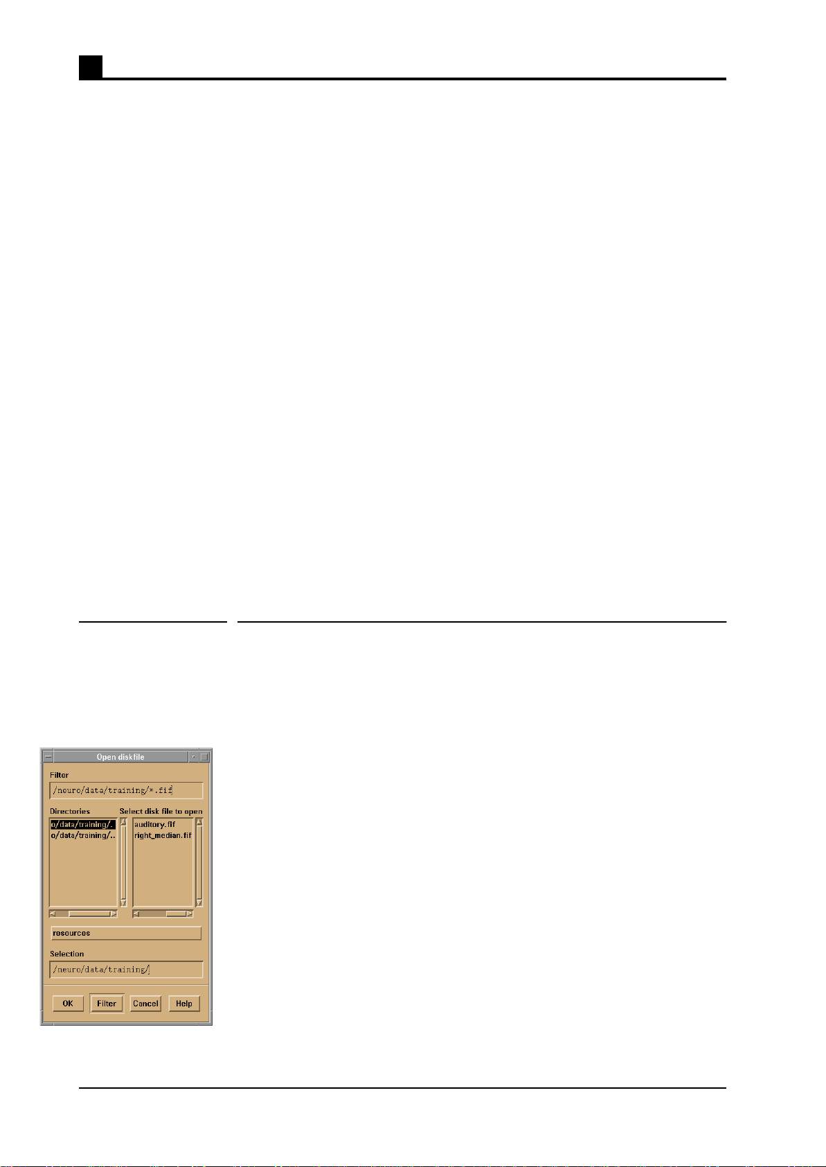
1.3 Using file selection boxes
In several phases of the analysis one must select a file to be loaded or pro-
cessed. In most cases user can do this selection using a file selection box
dialog. The figure on the left shows an example dialog.
On the top there is a field that contains a directory specification along with
a file mask. This specification defines the directory from which a file can
be selected, and the subset of files within this directory that are shown as
possible choices. If the mask part after the last slash in specification is
character *, all files in the directory are shown. If the mask contains other
characters, the file names show must contain the same pattern. For exam-
ple specification /neuro/dacq/tuning/*.tnp would select all files in direc-
tory /neuro/newdata/test that end to string “.tnp”.
Below the directory specification there are two selection boxes. The left
one lists all subdirectories to the directory specified above. You can
change the currently viewed directory easily by double clicking a direc-
tory name in this list. The right list contains all the files matching the
directory specification. Note that the parent directory is noted by filename
“..” (two dots) in these lists.

User interface basics 1
NM21283A-A 7
Below the lists there is a text field that shows the currently selected file. If
you must create a new file that does not exist yet, you can enter the new
name in this field and press ok button. For details of editing text fields see
“Using text fields” on page 5.
To select a file that already exists, double click the name of the file in the
right selection box. You may also select the file name by clicking it once,
and then pressing the ok button.
If you need to cancel the ongoing selection, press the cancel button on the
bottom of the dialog.

1User interface basics
8 NM21283A-A

NM21283A-A 9
2
CHAPTER 2 Getting started
This chapter gives you an overview of the program, explains how to start
and stop it and provides some basic aspects that you need to know.
2.1 Beginning a session
The tuner program can be started in three ways:
• Selecting the Tuner... button in the Tools menu of the acquisition pro-
gram. Measurements using acquisition program should be stopped
before starting the tuner. See “Data acquisition User’s Manual” for
details of the acquisition program.
• Using the graphical user interface of the operating system by double
clicking the tuner icon in “Maintenance” toolbox under the “MEG
analysis” toolbox.
• Giving a suitable command in UNIX shell. For the proper command
and options, refer to Appendix A.
Only one tuning program should be running at any time. If the tuning pro-
gram is already running on the same system, the new starting program
shows an question dialog warning about the already running program. In
such a case you should answer OK to stop the new one and find out who is
running the program. It is possible that you get this message even if there
is no other instance of the program running, for example if the program
was killed or it died unexpectedly. If you are sure that there is no other
copy running you can go on using the program by responding with Can-
cel button.
After starting the program, a user interface similar to Figure 2.1 appears.
On the top of the window is a menu bar that allows access to several oper-
ations and parameter settings. Major part of the window area is taken by a
graphics area which is used to show the results of current operation. On
the left are controls to show and alter manually the SQUID working point
parameters and two large buttons that are used to initiate and stop opera-
tions. These buttons will be called “start button” and “stop button”
throughout the manual. The labels on these buttons change depending on
the situation. In the bottom of the window is a status display area and con-
trols to alter graphics display scales.

2Getting started
10 NM21283A-A
The status display area is divided in four regions described here from left
to right:
• The leftmost small icons show the state of the acquisition.
• Area showing current helium level in the dewar.
• Status message area which shows information about ongoing activities.
• Information area showing variable user data like cursor position.
• Scale controls of the graphics display.
2.2 Using online HELP
The Help menu contains currently only a button which shows the version
information about the program. No online help is currently available.
2.3 Ending a session
To exit the program, select Exit from the File menu. This menu is inactive
(gray) during active measurements, so if the menu is unavailable you must
stop the ongoing measurement by pressing the “stop button”. It is recom-
mended that you exit the program after checking the noise levels or tuning
before starting a new acquisition.
Figure 2.1 Main window of the SQUID tuning program
Menu bar
Working point
View channel
Start button
Stop button
State icons
Helium level Status text area Graphics controls
Graphics area
Information area
controls

NM21283A-A 11
3
CHAPTER 3 Basic tuning operations
This chapter explains how to measure white noise level of the sensors,
automatic fine tuning, and heating of the sensors.
3.1 Measuring the sensor noise level
The tuner program can be used to check the white noise level of all the
sensors. This can be done before the measurements to check that all chan-
nels are working properly.
To measure white noise levels using Tuner:
1. Stop any ongoing acquisition by pressing stop button of the acquisition
program, and wait for the measurement to stop.
2. Start the tuning program (if not running yet). See “Beginning a ses-
sion” on page 9.
3. Press the large “Measure noise” button on the left.
Warning: If there was a measurement running when the tuner was
started, the start button is gray, and no tuner measurements can be initi-
ated. In this case, one must exit the tuner, stop the normal acquisition
measurement, and then restart the tuner again.
Warning: Acquisition program can not perform measurements if the
tuner is accessing the measurement system. To enable measurements,
press stop button to stop current operation, and then another time to
release the collector (software part responsible for delivering the magne-
tometer data). It is recommended that you then exit the tuning program,
even though that is not necessary to perform normal acquisition.
The program now starts measuring the noise level of the system. The
noise level of all channels is shown on a bar display in the display area.
Normally all bars should be red and display value between 2 to 5
( for gradiometers). Small negative bars indicate channels
that are saturated and probably are not operating in flux locked mode (not
functioning properly). Note that the colors can be adjusted personally. The
above description refers to default colors.
fT Hz⁄
fT cm Hz()⁄

3Basic tuning operations
12 NM21283A-A
If the noise values look good you can press the “stop button”, exit the pro-
gram, and go on measuring with the acquisition program. If not, proceed
to tune the channels. This is explained in the next section.
3.2 Fine tuning
Normally the program is used to tune slight offsets from a good operating
point that is set after the installation of the system or thermal cycling. This
is referred as fine tuning.
Before tuning one should measure the noise level. See “Measuring the
sensor noise level” on page 11. If it is abnormally high, check that the
door of the shielded room is closed. If the noise still looks very high, or
some channels are saturated (small black bars appear in the display), try
heating the noisy channels. See “Heating sensors” on page 13. If the over-
all noise level is very high, you probably need to load suitable tuning set-
tings from a file before doing the fine tuning. See “About saving and
loading settings” on page 14. Contact your administrator to find out the
correct tuning file.
When the channels seem to work properly, but the noise level is higher
than normally, running the auto-tuning routine of the tuning program
should be able to fine tune the noise levels to normal.
To tune sensors automatically:
1. Start a noise level measurement.
2. Press the “start button” again (the same button that was used to start the
noise measurement). The button should now have text Tune on it.
3. Wait until the tuning has obtained good noise values. (Or, hopefully
not, failed to tune the noise.) The tuning does not stop automatically. It
continues until it is explicitly stopped.
4. Press Stop tuning button.
5. Press Stop collector button (the same stop button as before which now
has different text on it), to release the acquisition system for normal
measurements.
Warning: All measurements should be made with the doors of the
shielded room closed.
Warning: Heat single noisy channels before tuning. Tuning may success
even with flux trapped SQUID but then the tuning is off when the sensor
is later returned to its normal state.

Basic tuning operations 3
NM21283A-A 13
Warning: Tuning for excessively long times (>5 min.) does not make the
tuning better. Instead, if the noise level is limited by something else than
SQUID noise, the tuning settings may drift to unstable values.
3.3 Resetting channels
The SQUID sensors are operated in so called flux locked mode. See
“SQUID electronics of Vectorview” on page 29. In some situations the
electronics is not capable following the signal and the output gets satu-
rated. This can be due to very strong signals (e.g. environmental low fre-
quency drift) or sharp transients. To get the sensor working again, the
integrator in the feed back loop and the zeroing mechanism (high pass fil-
ter), need to be reset. Saturated channels that need to be reset are repre-
sented as small negative bars in the noise display.
To reset all channels:
1. Select Commands > Reset electronics from the menus.
3.4 Heating sensors
The coils and the SQUIDs in a sensor unit contain very thin superconduct-
ing film. Sometimes when the sensor is exposed to strong (relative to the
signals measured) magnetic field, these films “trap” magnetic flux. Strong
magnetic field can penetrate the film destroying the superconductivity
from a small patch of the film so that the field can go through it. Typically
the impurities in the films cause these “holes” to stick at some fixed posi-
tion, thus this phenomenon is often called “flux trapping”.
The flux trapping in the sensor coils is not problematic if the flux really
stays in place. Unfortunately it is quite common that the trapped flux
moves between e.g. two points. Since the flux pinned into the film is
always strong, even a very small movement cause severe jumping in the
sensor signal.
If the flux trapping occurs so that the flux penetrates the Josephson junc-
tions in the SQUID, the sensor ceases to work. If the pinning point is in
near neighborhood of the junctions, the extra field leaking through the
junctions cause the modulation depth of the SQUID to diminish. This can
manifest itself as increased noise or, if the effect is reasonably small, as
moving of the optimal operating point (bias, offset, and gate voltages) to
somewhat different values.
The magnetic flux in the thin films of the sensor can be removed by heat-
ing the sensor above the critical temperature of the films, and then letting
it cool down again. The sensors in Vectorview are equipped with small

3Basic tuning operations
14 NM21283A-A
hearing resistors, so that this can be easily achieved by feeding a suitable
current pulse into the resistor. Note that each sensor unit contains three
SQUIDs, so three channels are always heated together.
To heat a single sensor that contains a particular channel:
1. Select the view channel by entering the channel name to the selection
box of the working point controls at the left side of the display area.
Press return and check that the name of the channel appear on the top
of the display.
2. Select Command > Heat sensor from the menus.
To heat all the sensors:
1. Select Command > Heat all sensors from the menus.
If you are making a noise measurement, you need also reset the electron-
ics after heating. See “Resetting channels” on page 13.
3.5 About saving and loading settings
Tuning settings can be saved on disk and loaded back to magnetometer
later on. Recommended practice is that there should be two or three stan-
dard settings files that contain carefully made good values for normal
usage and some special situations like using the device just after helium
filling or when the helium level is very low. In normal conditions one
good setting file should be enough.
If the automatic fine tuning of the system does not succeed, one should try
first to heat bad channels and if that is not enough, load a well known tun-
ing setting file. If this tuning still fails, contact your system administrator
to find out what has changed.
It is not recommended that the tuning settings are saved after each fine
tuning and then reloaded when tuning is needed next time, since then the
tuning settings files tend to “drift” and nobody really knows how the sys-
tem should perform when some particular file is used. It is usually better
to have fixed files that are saved only by the administrative personnel so
that the expected performance is known and possible changes in the sys-
tem can be detected.
To load tuning settings into tuner and magnetometer:
1. Select File > Load tunings from the menu. A dialog will pop up.
2. If the file suggested by the dialog is the one you want to load, press OK
to load the file. Otherwise press Load other to pop up an ordinary file
selection box and use it to select the file you want to load. See “Using
file selection boxes” on page 6.
This manual suits for next models
1
Table of contents


