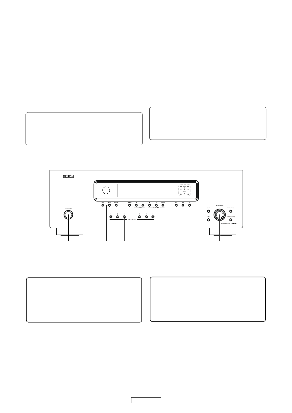
Denon TU-604CI - Multi-Zone Dual AM/FM Tuner User manual

Denon Brand Company, D&M Holdings lnc.
e
Ver. 1
SERVICE MANUAL
AM-FM / XM MULTIPLE TUNER
MODEL JP E3 E2 EK E2A E1C E1K EUT
TU-604CI
33
●For purposes of improvement, specifications and
design are subject to change without notice.
●Please use this service manual with referring to the
operating instructions without fail.
●Some illustrations using in this service manual are
slightly different from the actual set.
注 意
サービスをおこなう前に、このサービスマニュアル
を必ずお読みください。本機は、火災、感電、けが
などに対する安全性を確保するために、さまざまな
配慮をおこなっており、また法的には「電気用品安
全法」にもとづき、所定の許可を得て製造されてお
ります。従ってサービスをおこなう際は、これらの
安全性が維持されるよう、このサービスマニュアル
に記載されている注意事項を必ずお守りください。
●本機の仕様は性能改良のため、予告なく変更すること
があります。
●補修用性能部品の保有期間は、製造打切後 8 年です。
●修理の際は、必ず取扱説明書を参照の上、作業を行っ
てください。
●本文中に使用しているイラストは、説明の都合上現物
と多少異なる場合があります。
X0369 V.01 DE/CDM 0805

2
TU-604CI
Please heed the points listed below during servicing and inspection.
◎Heed the cautions!
Spots requiring particular attention when servicing, such
as the cabinet, parts, chassis, etc., have cautions indicated
on labels or seals. Be sure to heed these cautions and the
cautions indicated in the handling instructions.
◎Caution concerning electric shock!
(1) An AC voltage is impressed on this set, so touching in-
ternal metal parts when the set is energized could
cause electric shock. Take care to avoid electric shock,
by for example using an isolating transformer and
gloves when servicing while the set is energized, un-
plugging the power cord when replacing parts, etc.
(2)There are high voltage parts inside. Handle with extra
care when the set is energized.
◎Caution concerning disassembly and
assembly!
Though great care is taken when manufacturing parts from
sheet metal, there may in some rare cases be burrs on the
edges of parts which could cause injury if fingers are
moved across them. Use gloves to protect your hands.
◎Only use designated parts!
The set's parts have specific safety properties (fire resis-
tance, voltage resistance, etc.). For replacement parts, be
sure to use parts which have the same properties. In par-
ticular, for the important safety parts that are marked zon
wiring diagrams and parts lists, be sure to use the desig-
nated parts.
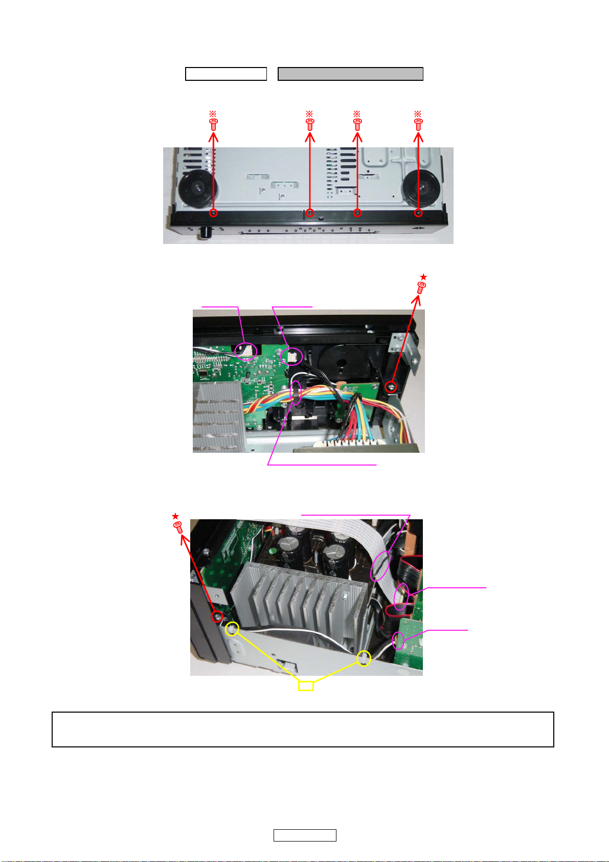
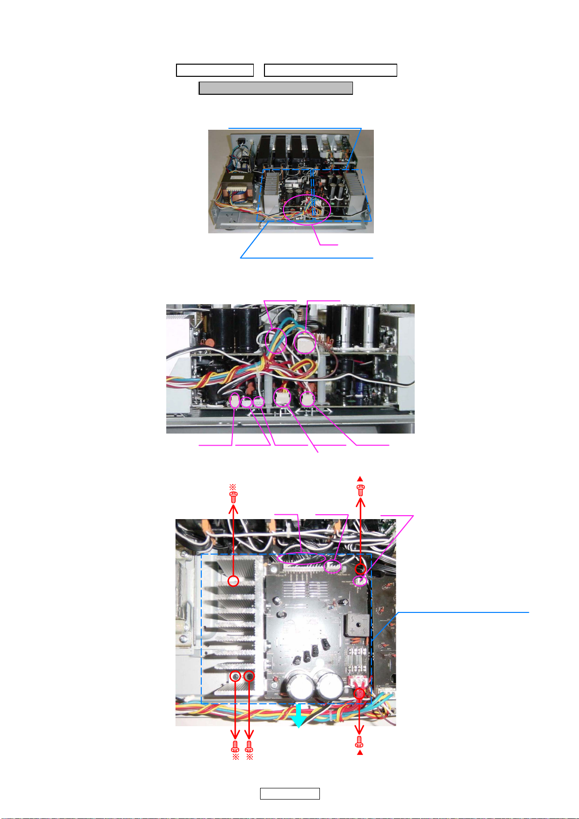
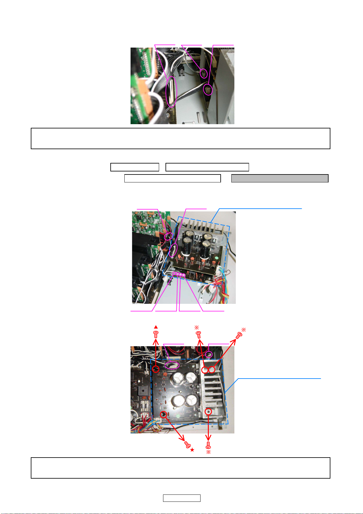
◎Be sure to mount parts and arrange
the wires as they were originally!
For safety reasons, some parts use tape, tubes or other in-
sulating materials, and some parts are mounted away from
the surface of printed circuit boards. Care is also taken with
the positions of the wires inside and clamps are used to
keep wires away from heating and high voltage parts, so
be sure to set everything back as it was originally.
◎Inspect for safety after servicing!
Check that all screws, parts and wires removed or discon-
nected for servicing have been put back in their original po-
sitions, inspect that no parts around the area that has been
serviced have been negatively affected, conduct an insu-
lation check on the external metal connectors and between
the blades of the power plug, and otherwise check that
safety is ensured.
(Insulation check procedure)
Unplug the power cord from the power outlet, disconnect
the antenna, plugs, etc., and turn the power switch on. Us-
ing a 500V insulation resistance tester, check that the in-
sulation resistance between the terminals of the power
plug and the externally exposed metal parts (antenna ter-
minal, headphones terminal, microphone terminal, input
terminal, etc.) is 1MΩor greater. If it is less, the set must
be inspected and repaired.
Concerning important safety
parts
Many of the electric and structural parts used in the set
have special safety properties. In most cases these prop-
erties are difficult to distinguish by sight, and using re-
placement parts with higher ratings (rated power and
withstand voltage) does not necessarily guarantee that
safety performance will be preserved. Parts with safety
properties are indicated as shown below on the wiring dia-
grams and parts lists is this service manual. Be sure to re-
place them with parts with the designated part number.
(1) Schematic diagrams ... Indicated by the zmark.
(2) Parts lists ... Indicated by the zmark.
Using parts other than the designated
parts could result in electric shock, fires or
other dangerous situations.
SAFETY PRECAUTIONS
The following check should be performed for the continued protection of the customer and service technician.
LEAKAGE CURRENT CHECK
Before returning the unit to the customer, make sure you make either (1) a leakage current check or (2) a line to chassis
resistance check. If the leakage current exceeds 0.5 milliamps, or if the resistance from chassis to either side of the
power cord is less than 460 kohms, the unit is defective.
CAUTION
CAUTION

3
TU-604CI
サービス、点検時にはつぎのことにご注意願います。
◎注意事項をお守りください!
サービスのとき特に注意を必要とする個所については
キャビネット、部品、シャーシなどにラベルや捺印で注意
事項を表示しています。これらの注意書きおよび取扱説明
書などの注意事項を必ずお守りください。
◎感電に注意!
(1) このセットは、交流電圧が印加されていますので通電
時に内部金属部に触れると感電することがあります。
従って通電サービス時には、絶縁トランスの使用や手
袋の着用、部品交換には、電源プラグを抜くなどして
感電にご注意ください。
(2) 内部には高電圧の部分がありますので、通電時の取扱
には十分ご注意ください。
◎分解、組み立て作業時のご注意!
板金部品の端面の『バリ』は、部品製造時に充分管理をし
ておりますが、板金端面は鋭利となっている箇所が有りま
すので、部品端面に触れたまま指を動かすとまれに怪我を
する場合がありますので十分注意して作業して下さい。手
の保護のために手袋を着用してください。
◎指定部品の使用!
セットの部品は難燃性や耐電圧など安全上の特性を持っ
たものとなっています。従って交換部品は、使用されてい
たものと同じ特性の部品を使用してください。特に配線
図、部品表にz印で指定されている安全上重要な部品は
必ず指定のものをご使用ください。
◎部品の取付けや配線の引きまわしは、
元どおりに!
安全上、テープやチューブなどの絶縁材料を使用したり、
プリント基板から浮かして取付けた部品があります。また
内部配線は引きまわしやクランパーによって発熱部品や
高圧部品に接近しないように配慮されていますので、これ
らは必ず元どおりにしてください。
◎サービス後は安全点検を!
サービスのために取り外したねじ、部品、配線などが元ど
おりになっているか、またサービスした個所の周辺を劣化
させてしまったところがないかなどを点検し、外部金属端
子部と、電源プラグの刃の間の絶縁チェックをおこなうな
ど、安全性が確保されていることを確認してください。
(絶縁チェックの方法)
電源コンセントから電源プラグを抜き、アンテナやプラグ
などを外し、電源スイッチを入れます。500V 絶縁抵抗計
を用いて、電源プラグのそれぞれの端子と外部露出金属部
[アンテナ端子、ヘッドホン端子、マイク端子、入力端子
など]との間で、絶縁抵抗値が1 MΩ 以上であることを
確認してください。この値以下のときはセットの点検修理
が必要です。
安全上重要な部品について
本機に使用している多くの電気部品、および機構部品は安
全上、特別な特性を持っています。この特性はほとんどの
場合、外観では判別つきにくく、またもとの部品より高い
定格(定格電力、耐圧)を持ったものを使用しても安全性
が維持されるとは、限りません。安全上の特性を持った部
品は、このサービスマニュアルの配線図、部品表につぎの
ように表示していますので必ず指定されている部品番号
のものを使用願います。
(1) 配線図…zマークで表示しています。
(2) 部品表…zマークで表示しています。
指定された部品と異なるものを使用した場
合には、感電、火災などの危険を生じる恐
れがあります。
注 意
注 意

4
TU-604CI
DIMENSION

5
TU-604CI
ワイヤー整形図
調整や部品の交換等により、ワイヤー類の結束をはずした
り移動させた場合には、それらの作業が完了した時点でワ
イヤーの整形をおこなってください。正しく整形されてい
ないとノイズ発生の原因となることがあります。
上面からみたワイヤー整形
WIRE ARRANGEMENT
If wire bundles are untied or moved to perform adjustment or
parts replacement etc., be sure to rearrange them neatly as
they were originally bundled or placed afterward.
Otherwise, incorrect arrangement can be a cause of noise
generation.
Wire arrangement viewed from the top
Back Panel side
Front Panel side

6
TU-604CI
サービス時の注意事項
マルチチューナーの初期化について
マイコンやマイコン周辺部品、Digital 基板等を交換した場
合は、マルチチューナーの初期化をおこなってください。
1. "ON/STANDBY" ボタンを押して、起動状態にします。
2. "MODE" ボタンと "TUNER3" ボタンを同時に押しなが
ら、"SELECT/ENTER" ボタンを 3 秒以上押します。
3. ディスプレイ表示が約 1秒間隔で点滅するのを確認後、
2つのボタンから指を離します。
*マイコンが初期化されます。
注意 :・上記 3 の状態にならない場合は、もう一度操作 1
からやり直してください。
・初期化を行うとお客様が設定した内容が工場出
荷状態に戻りますので、あらかじめ設定内容を
控えておき初期化後再設定してください。
●Optionboard は修理対象外の製品です。
サービス対応は「製品交換」のみとなります。
<Optionboard>
・ ACD-AMFM
・ ACD-XMSIR
・ ACD-HD
・ ACD-DAB
CAUTION IN SERVICING
Initializing MULTI TUNER
MULTI TUNER initialization should be performed when the
µcom and peripheral parts of µcom, and Digital P.W.B. are re-
placed.
1. Press the “ON/STANDBY” button, starting state it does.
2. Press the “SELECT/ENTER” button and hold it in for at
least 3 seconds, while simultaneously pressing the
“MODE” button and the “TUNER 3” button.
3. Check that the entire display is flashing with an interval of
about 1 second, and release your fingers from the 2 but-
tons.
*The microprocessor will be initialized.
Note:・If step 3 does not work, start over from step 1.
・All user settings will be lost and this factory setting
will be recovered when this initialization mode.
So make sure to m+emorize your setting for re-
storing after the initialization.
ON / STANDBY SELECT / ENTERMODE TUNER 3
●The parts of Option board are not serviceable.
Please replace the product itself.
<Option board>
• ACD-AMFM
• ACD-XMSIR
• ACD-HD
• ACD-DAB

7
TU-604CI
DISASSEMBLY
• Disassemble in order of the arrow of the figure of following flow.
下記フロー図の矢印の順番にはずしてください。
• In the case of the re-assembling, assemble it in order of the reverse of the following flow.
再組み立ての場合は、下記のフローの逆の順番に組立ててください
• In the case of the re-assembling, observe "attention of assembling" it.
再組み立ての場合は、「組立のご注意」を遵守してください。
CABINET TOP
PANEL FRONT SUB ASS
Y
CHASSIS BACK SUB ASS
Y
Refer to "DISASSEMBLY Refer to "DISASSEMBLY
1.PANEL FRONT SUB ASSY" 4.CHASSIS BACK SUB ASSY"
and "EXPLODED VIEW" and "EXPLODED VIEW"
POWERON UNIT AMFM BUILT-IN P.W.B UNIT ASSY
(Ref. No. of EXPLODED VIEW : 7) (Ref. No. of EXPLODED VIEW : 42)
FRONT P.W.B UNIT
(Ref. No. of EXPLODED VIEW : 10)
HEAT SINK MAIN L SUB ASS
Y
STBY UNIT ASS
Y
IO OPTION UNIT /
Refer to "DISASSEMBLY Refer to "DISASSEMBLY IO BUILT-IN UNIT /
2.HEAT SINK MAIN L SUB ASSY" 7.STBY UNIT ASSY ETHERNET P.W.B UNIT ASS
Y
and "EXPLODED VIEW" and "EXPLODED VIEW" Refer to "DISASSEMBLY
POWER2 UNIT STBY1 UNIT 5.IO OPTION UNIT /
(Ref. No. of EXPLODED VIEW : 16) (Ref. No. of EXPLODED VIEW : 33) IO BUILT-IN UNIT /
POWER3 UNIT STBY2 UNIT ETHERNET P.W.B UNIT ASSY"
(Ref. No. of EXPLODED VIEW : 17) (Ref. No. of EXPLODED VIEW : 34) and "EXPLODED VIEW"
IO OPTION UNIT
(Ref. No. of EXPLODED VIEW : 35)
HEAT SINK MAIN R SUB ASS
Y
TRANS IO BUILT-IN UNIT
Refer to "DISASSEMBLY Refer to "DISASSEMBLY (Ref. No. of EXPLODED VIEW : 36)
3.HEAT SINK MAIN R SUB ASSY" 8.TRANS" ETHERNET P.W.B UNIT ASSY
and "EXPLODED VIEW" and "EXPLODED VIEW" (Ref. No. of EXPLODED VIEW : 37)
POWER1 UNIT TRANS
(Ref. No. of EXPLODED VIEW : 15) (Ref. No. of EXPLODED VIEW : 28)
XMBUS UNIT
(Ref. No. of EXPLODED VIEW : 18) MAIN P.W.B UNIT ASS
Y
Refer to "DISASSEMBLY
6.MAIN P.W.B UNIT ASSY
and "EXPLODED VIEW"
MAIN P.W.B UNIT ASSY
(Ref. No. of EXPLODED VIEW : 30)
Front side
Picture B
Picture E
Picture A
Picture C Picture D
Picture G
Picture F
Top view
The viewpoint of each photograph
(photography direction)
各図の視点(撮影方向)

8
TU-604CI
1. PANEL FRONT SUB ASSY
(1) Remove the screws.(ねじをはずす。)
(2) Disconnect the connector wires and remove the screw.(コネクタワイヤーとねじをはずす。)
Please refer to
"EXPLODED VIEW "
for the disassembly method of each P.W.B included in PANEL FRONT SUB ASSY .
PANELFRONTSUBASSY の各基板のはずしかたは "EXPLODEDVIEW" を参照してください。
proceeding (手順): CABINET TOP →PANEL FRONT SUB ASSY
Bottom view
CORD HOLDER : Loose
CP1003 CP1001
Picture F
CORD HOLDER : Loose
CP1102
FFC CABLE
Picture C
cut

9
TU-604CI
2. HEAT SINK MAIN L SUB ASSY
(1) Disconnect the connector wires. (コネクタワイヤーをはずす。)
(2) Disconnect the connector wires and remove the screws.(コネクタワイヤーとねじをはずす。)
proceeding (手順): CABINET TOP →PANEL FRONT SUB ASSY
→HEAT SINK MAIN L SUB ASSY
(A)
Picture A
HEAT SINK MAIN R SUBASSY
HEAT SINK MAIN L SUB ASSY
CP302 CN303 CN302 CP301 CP305
CP304 CP303
Picture A
Detail : (A)
CP307 CP306
Top view
(B)
HEAT SINK MAIN L SUB ASSY

10
TU-604CI
(3) Disconnect the connector wires.(コネクタワイヤーをはずす。)
Please refer to
"EXPLODED VIEW "
for the disassembly method of each P.W.B included in HEAT SINK MAIN L SUB ASSY .
HEATSINKMAINLSUBASSY の各基板のはずしかたは "EXPLODEDVIEW" を参照してください。
3. HEAT SINK MAIN R SUB ASSY
(1) Disconnect the connector wires.(コネクタワイヤーをはずす。)
(2) Disconnect the connector wires and remove the screws.(コネクタワイヤーとねじをはずす。)
Please refer to
"EXPLODED VIEW "
for the disassembly method of each P.W.B included in HEAT SINK MAIN R SUB ASSY .
HEATSINKMAINRSUBASSY の各基板のはずしかたは "EXPLODEDVIEW" を参照してください。
Picture D
Detail : (B) CP118 CN311 CP308
proceeding (手順): CABINET TOP →PANEL FRONT SUB ASSY
→HEAT SINK MAIN L SUB ASSY →HEAT SINK MAIN R SUB ASSY
CP309
CP119
CN304 CN305 CN307 CN308
Picture D
HEAT SINK MAIN R SUBASSY
CP309 CP119
Top view
HEAT SINK MAIN R SUBASSY

11
TU-604CI
4. CHASSIS BACK SUB ASSY
(1) Remove the P.W.B HOLDER and disconnect the connector wire.(P.W.B ホルダーとコネクタワイヤーをはずす。)
proceeding (手順): CABINET TOP →CHASSIS BACK SUB ASSY
CHASSIS BACK SUB ASSY
AMFM BUILT-IN P.W.B UNITASSY
Top view
P.W.B HOLDER
CP1102
Picture C
ETHERNET P.W.B UNIT ASSY
AMFM BUILT-IN P.W.B UNITASSY

12
TU-604CI
(2) Disconnect the connect wires.(コネクタワイヤーをはずす。)
(3) Remove the screws.(ねじをはずす。)
Please refer to
"EXPLODED VIEW "
for the disassembly method of each P.W.B included in CHASSIS BACK SUB ASSY .
CHASSISBACKSUBASSY の各基板のはずしかたは "EXPLODEDVIEW" を参照してください。
CN401 CP602
CN402 CP603
(A)
Picture A
CP456
cut
Top view
Detail : (A)
ع
Picture B

13
TU-604CI
5. IO OPTION UNIT / IO BUILT-IN UNIT / ETHERNET P.W.B UNIT ASSY
(1) Remove the IO OPTION UNIT , IO BUILT-IN UNIT and ETHERNET UNIT.(IOOPTIONUNIT と IOBUILT-INUNIT と
ETHERNETUNIT をはずす。)
6. MAIN P.W.B UNIT ASSY
Please refer to
"EXPLODED VIEW "
for the disassembly method of MAIN P.W.B UNIT ASSY.
MAINP.W.BUNITASSY のはずしかたは "EXPLODEDVIEW" を参照してください。
7. STBY UNIT ASSY
(1) Disconnect the connector wires and FFC Cables.(コネクタワイヤーと FFC ケーブルをはずす。)
Please refer to
"EXPLODED VIEW "
for the disassembly method of each P.W.B included in STBY UNIT ASSY.
STBYUNITASSY の各基板のはずしかたは "EXPLODEDVIEW" を参照してください。
proceeding (手順): CABINET TOP →CHASSIS BACK SUB ASSY
→IO OPTION UNIT / IO BUILT-IN UNIT / ETHERNET P.W.B UNIT ASSY
CP405
Picture B
CP1101 CP404 CP407
IO OPTION UNIT
ETHERNET P.W.B UNIT ASSY
IO BUILT-IN UNIT
proceeding (手順): CABINET TOP →CHASSIS BACK SUB ASSY
→IO OPTION UNIT / IO BUILT-IN UNIT / ETHERNET P.W.B UNIT ASSY
→MAIN P.W.B UNIT ASSY
proceeding (手順): CABINET TOP →CHASSIS BACK SUB ASSY
→STBY UNIT ASSY
Picture B
STBY2 UNIT
STBY1 UNIT
MAIN P.W.B UNITASSY

14
TU-604CI
8. TRANS
(1) Remove the PANEL FRONT ASSY.(PANELFRONTASSY をはずす。)
(2) Disconnect the connector wires.(コネクタワイヤーをはずす。)
(3) Disconnect the connector wires and remove the screws.(コネクタコードとねじをはずす。)
proceeding (手順): CABINET TOP →PANEL FRONT SUB ASSY →TRANS
Picture A
cut CP305
CP301
CP303
CP304
Picture B cut
CP453

15
TU-604CI
テストモードによるチェック方法
1. 動作仕様
起動状態にて下記の条件に該当した場合は、バージョン
情報を表示します。
起動方法 ( マイコンバージョン表示モード ):
"MODE" ボタンと"TUNER1" ボタンを同時に押しなが
ら、"SELECT/ENTER" ボタンを 3 秒以上押します。
その後、"SELECT/ENTER"JOG を右にまわすと内容を FL
Displayに表示します。
2. 表示順序
仕向地表示→メインマイコンバージョン情報→サブマ
イコンバージョン情報→イーサネット情報
CHECK WITH TEST MODE
1. Operation Spec
When the following conditions are satisfied at its starting
state, error information is displayed.
Starting method (µcom version display mode):
Press the “SELECT/ENTER” button and hold it in for at
least 3 seconds, while simultaneously pressing the
“MODE” button and the “TUNER 1” button.
Then, “SELECT/ENTER” JOG is turned clockwise and
the following information is displayed on FL Display.
2. Display Order
Destination information→Main-µcom versioninformation
→Sub-µcom version information →Ethernet information
SELECT / ENTERMODE TUNER 1

16
TU-604CI
---MEMO---

17
TU-604CI
TROUBLE SHOOTING
1. POWER
1.1. Power not turn on
1.2. Fuse is blown
Power not turn on
YES
Is the fuse blown?
NO
Refer to Fuse is blown.
YES
Are there any incomplete connections in
the connectors connecting between the
various circuit boards?
NO
Check for damage of the circuitry parts
and replace any defective parts.
YES
YES
Connect the connectors properly.
Is DC3.3V voltage supplied to the µcom?
NO
Is a DC3.3V voltage output when the cord
supplying the power to the µcom is
unplugged?
NO
Check the parts from µcom to the primary
circuitry and replace any defective parts.
YES YES
Check the µcom periphery circuitry and
replace any defective parts.
Check the circuitry and parts the µcom
for damage and short-circuits, and
replace any defective parts.
Fuse is blown
YES YES YES
Check for leaks or short circuits in the pri-
mary side parts, and replace any defec-
tive parts.
Check for short circuits in the rectifier
diodes and circuitry of the secondary side
rectifying circuits, and replace any defec-
tive parts.
Check for short circuits in the power stabi-
lizer unit's regulator output terminal and
the ground, and replace any defective
parts.
YES YES YES
After repairing, also replace the fuse.
トラブルシューティング
1. 電源
1.1. 電源が入らない
1.2. ヒューズが断線している
電源が入らない
YES
ヒューズは断線していませんか?
NO
ヒューズが断線しているを参照してくだ
さい。
YES
各基板間を接続しているコネクターに不
完全な接続部分はありますか?
NO
回路の部品の破損を確認し、不良部品を
交換してください。
YES
YES
コネクターを正しく接続してください。
マイコンに DC3.3V が供給されています
か?
NO
マイコンヘ電源を供給しているコードを
抜いて DC3.3V が出力されていますか?
NO
マイコン〜 1 次回路までの部品を確認し、
不良部品を交換してください。
YES YES
マイコン周辺回路を確認し、不良部品を
交換してください。
マイコン電源までの回路および部品の破
損や短絡を確認し、不良部品を交換して
ください。
ヒューズが断線している
YES YES YES
1 次側の部品にリークまたは短絡を確認
し、不良部品を交換してください。
2 次側のそれぞれの整流回路で、整流
ダイオードおよび回路の短絡を確認し、不良
部品を交換してください。
電源安定化部のレギュレータの出力端子
と GND の短絡を確認し、短絡している場
合は、不良部品を交換してくだい。
YES YES YES
修理後、FUSE も交換してください。

18
TU-604CI
BLOCK DIAGRAM

19
TU-604CI
SEMICONDUCTORS
Only major semiconductors are shown, general semiconductors etc. are omitted to list.
主な半導体を記載しています。汎用の半導体は記載を省略しています。
1. IC’s
M30626FJPFP (IC103)
M30626FJPFP Terminal Function
Pin Pin
Function Pin Name I/O
STBY
STOP
Active Function
1
P96/SOUT4
VFD_DT O O/L O/L SERIAL
FLD driver control terminal (16-ST-87GINK) DATA
2 P95/CLK4 VFD_CLK O O/L O/L SERIAL
FLD driver control terminal (16-ST-87GINK) CLOCK
3 P94/TB4 FLD_RST O O/L O/L L:RESET FLD driver reset control terminal (16-ST-87GINK)
RESET
4 P93/TB3 VFD_CS O O/L O/L
H:DATA transfer
prohibition
FLD driver control terminal (16-ST-87GINK) CIP
SELECT
5
P92/SOUT3
ETHER_SPI_TX(MOEI)
O O/L O/L SERIAL ETHER SPI communication control terminal TX
6 P91/SIN3
ETHER_SPI_RX(MIEO)
I O/L O/L SERIAL ETHER SPI communication control terminal RX
7 P90/CLK3 ETHER_SPI_CLK O O/L O/L SERIAL
ETHER SPI communication control terminal CLOCK
8 BYTE BYTE GND - - Single chip mode setting
9 CNVCS CNVSS - - - UP GRADE PIN
10 P87 MAIN_PWR_STNDBY O O/L O/L H:ACTIVE POWER RELAY CONTROL
11 P86 NC O O/L O/L - PULL-DOWN
12 RESET HARD RST I I I Lv u-COM RESET SIGNAL INPUT

20
TU-604CI
13 XOUT XOUT O - - OSILATOR CONNECTION
14 VSS Vss GND - - GND
15 XIN XIN I I I OSILATOR CONNECTION
16 VCC Vcc1 3.3V - - POWER 3.3V
17 P85/NMI NMI I - - UP GRADE PIN
18 P84/INT2 PWR_DOWN I I I Fall Edge&L Power failure detection
19 P83/INT1 REMOCON I I I Rise Edge&H Remote control receiver terminal
20 P82/INT0 ETHER_REQ I I I Fall Edge&L EATHERNET REQUEST
21 P81 NC O O/L O/L - PULL-DOWN
22 P80 NC O O/L O/L - PULL-DOWN
23 P77 NC O O/L O/L - PULL-DOWN
24 P76 NC O O/L O/L - PULL-DOWN
25 P75 NC O O/L O/L - PULL-DOWN
26 P74 NC O O/L O/L - PULL-DOWN
27 P73/CTS2 NC O O/L O/L - PULL-DOWN
28 P72/CLK2 TU CLK O O/L O/L TUNER SUB CPU communication control
terminal CLOCK
29 P71/RXD2 TU RX(MISO) I I O/L UART TUNER SUB CPU communication control
terminal RX
30 P70/TXD2 TU TX(MOSI) O O/L O/L UART TUNER SUB CPU communication control
terminal TX
31 P67/TXD1 RS232C_TX(MORI) O O/L O/L UART RS232C SIGNAL OUTPUT
32 P66/RXD1 RS232C_RX(MIRO) I I O/L UART RS232C SIGNAL INPUT
33 P65/CLK1 TU6_CS O O/L O/L TUNER6 communication control CHIP SELECT
34 P64/CTS1 TU6_REQ I O/L O/L Lv TUNER6 SUB CPU communication control
terminal REQUEST
35 P63/TXD0 ETHER_TX(MOEI) O O/L O/L UART EATHERNET communication terminal TX
36 P62/RXD0 ETHER_RX(MIEO) I O/L O/L UART EATHERNET communication terminal RX
37 P61/CLK0 RST_TU6 O O/L O/L L:ACTIVE TUNER6 SUB CPU RESET
38 P60/CTS0 MUTE RL6 O O/L O/L H:ACTIVE TUNER6 MUTE RELAY control terminal
39 P57 MUTE TR6 O O/L O/L H:ACTIVE TUNER6 MUTE TRANSISTOR control terminal
40 P56 TU5_CS O O/L O/L TUNER5 communication control CHIP SELECT
41 P55/EPM RS232C_EPM I I I UP GRADE PIN
42 P54 TU5_REQ I O/L O/L Lv TUNER5 SUB CPU communication control
terminal REQUEST
43 P53 RST_TU5 O O/L O/L L:ACTIVE TUNER5 SUB CPU RESET
44 P52 MUTE RL5 O O/L O/L H:ACTIVE TUNER5 MUTE RELAY control terminal
45 P51 MUTE TR5 O O/L O/L H:ACTIVE TUNER5 MUTE TRANSISTOR control terminal
46 P50/CE RS232C_CE O I I UP GRADE PIN
47 P47 TU4_CS O O/L O/L TUNER4 communication control CHIP SELECT
48 P46 TU4_REQ I O/L O/L Lv TUNER4 SUB CPU communication control
terminal REQUEST
49 P45 RST_TU4 O O/L O/L L:ACTIVE TUNER4 SUB CPU RESET
50 P44 MUTE RL4 O O/L O/L H:ACTIVE TUNER4 MUTE RELAY control terminal
51 P43 MUTE TR4 O O/L O/L H:ACTIVE TUNER4 MUTE TRANSISTOR control terminal
52 P42 TU3_CS O O/L O/L TUNER3 communication control CHIP SELECT
53 P41 TU3_REQ I O/L O/L Lv TUNER3 SUB CPU communication control
terminal REQUEST
54 P40 RST_TU3 O O/L O/L L:ACTIVE TUNER3 SUB CPU RESET
55 P37 MUTE RL3 O O/L O/L H:ACTIVE TUNER3 MUTE RELAY control terminal
56 P36 MUTE TR3 O O/L O/L H:ACTIVE TUNER3 MUTE TRANSISTOR control terminal
57 P35 TU2_CS O O/L O/L TUNER2 communication control CHIP SELECT
58 P34 TU2_REQ I O/L O/L Lv TUNER2 SUB CPU communication control
terminal REQUEST
59 P33 RST_TU2 O O/L O/L L:ACTIVE TUNER2 SUB CPU RESET
60 P32 MUTE RL2 O O/L O/L H:ACTIVE TUNER2 MUTE RELAY control terminal
61 P31 MUTE TR2 O O/L O/L H:ACTIVE TUNER2 MUTE TRANSISTOR control terminal
Pin Pin
Function Pin Name I/O
STBY
STOP
Active Function
Other manuals for TU-604CI - Multi-Zone Dual AM/FM Tuner
4
Table of contents
Other Denon Tuner manuals

Denon
Denon TU-1500 User manual

Denon
Denon TU-380RD User manual

Denon
Denon TU-235RD User manual

Denon
Denon TU-450 User manual

Denon
Denon Professional DN-U100 User manual

Denon
Denon TU-215RD User manual

Denon
Denon AV8802 Technical manual

Denon
Denon tu-245 User manual

Denon
Denon TU-280 User manual

Denon
Denon DN-700R User manual

Denon
Denon TU-560 User manual

Denon
Denon DN-700R User manual

Denon
Denon TU-604CI - Multi-Zone Dual AM/FM Tuner User guide

Denon
Denon TU-201SA User manual

Denon
Denon TU-6.5 User manual

Denon
Denon TU-1800DAB User manual

Denon
Denon TU-1500RD User manual

Denon
Denon DN-300H User manual

Denon
Denon TU-767 User manual

Denon
Denon TU-460 User manual