Elektra Bregenz DZ 6250-1 User manual
COOKER HOOD - User instructions
ODSAVAČ PAR – uživatelská příručka
EMHÆTTE - Brugervejledning
LIESITUULETIN – Käyttöohje
ΑΠΟΡΡΟΦΗΤΗΡΑΣ ΣΕ ΕΚΔΟΣΗ ΑΠΟΡΡΟΦΗΣΗΣ – Εγχειρίδιο χρήσης
ELSZÍVÓ KÜRTŐ – Használati utasítás
AVTREKKSKAPPE – Bruksanvisning
OKAP ZASYSAJĄCY - instrukcja obsługi
HOTĂ ASPIRANTĂ – Manual de utilizare
ВЫТЯЖНОЙ КОЛПАК - Руководство пользователя
SPISKÅPA – Bruksanvisning
CZ
DK
FIN
GR
GB
H
N
PL
CAPPA ASPIRANTE - Istruzioni per l'uso
DUNSTABZUGSHAUBE - Gebrauchsanweisung
CAMPANA EXTRACTORA - Manual de utilización
HOTTE DE CUISINE - Notice d'utilisation
AFZUIGKAP - Gebruiksaanwijzing
COIFA ASPIRANTE - Manual do usuário
I
D
E
F
NL
P
RUS
S
R
- 3 -
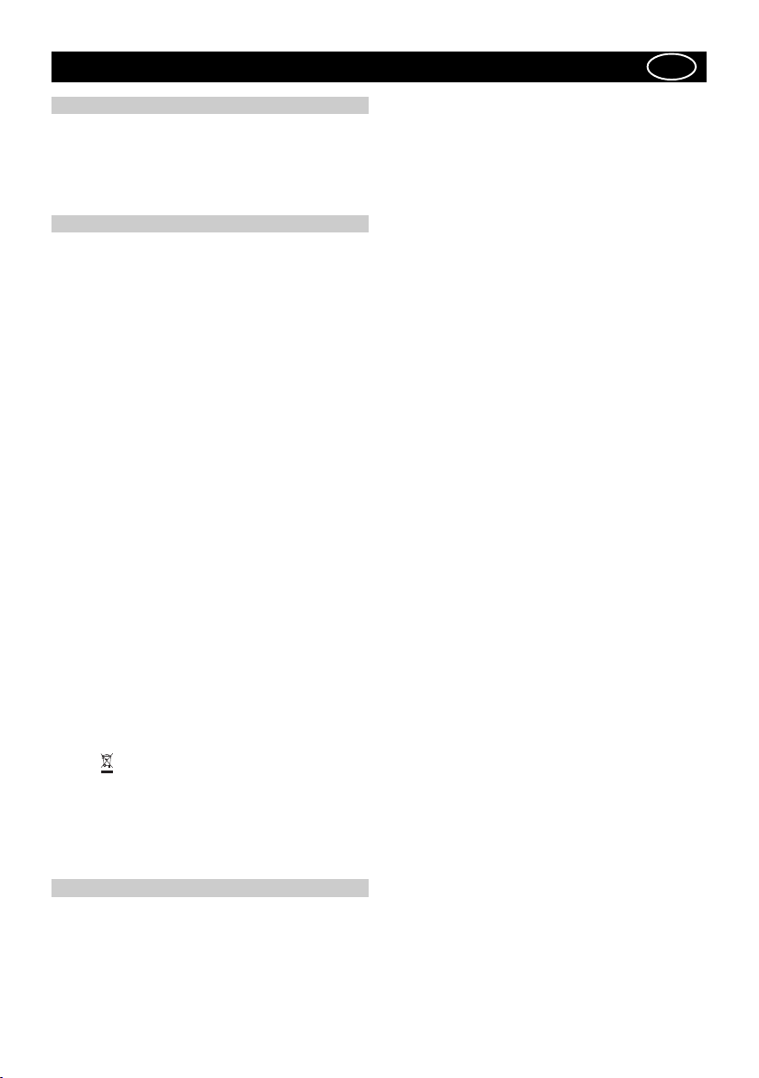
Fig.1
483
559.4
412.2
425.5
31.5
270
598 - 898
min 0 - max 76
min 32 - max 75
170
176
7582.5
48.5
270
420
min 0 - max 32
36
563
183
max 80 cm
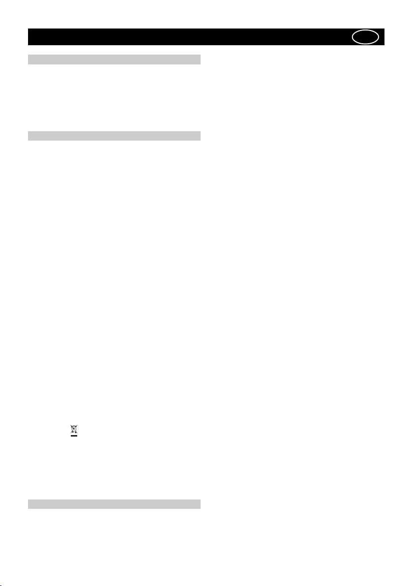
- 4 -
E
Boden van keukenkastje
Bord inferieur du meuble
Unterer Rand des üchenschrank
Lower edge of the kitchen cabinet
Bordo inferiore del pensile
Côte droit: bord anterieur de la hotte
Lato dx: bordo anteriore della cappa
Rechte Seite: vorderer Rand der Haube
Rechterzÿde: voorkant afzuigkap
Right side: front edge of the hood
E
Boden van keukenkastje
Bord inferieur du meuble
Unterer Rand des üchenschrank
Lower edge of the kitchen cabinet
Brdo inferiore del pensile
Côte droit: bord anterieur de la hotte
Lato dx: bordo anteriore della cappa
Rechte Seite: vorderer Rand der Haube
Rechterzÿde: voorkant afzuigkap
Right side: front edge of the hood
E
Boden van keukenkastje
Bord inferieur du meuble
Unterer Rand des üchenschrank
Lower edge of the kitchen cabinet
Bordo inferiore del pensile
E
Boden van keukenkastje
Bord inferieur du meuble
Unterer Rand des üchenschrank
Lower edge of the kitchen cabinet
Bordo inferiore del pensile
E
Boden van keukenkastje
Bord inferieur du meuble
Unterer Rand des üchenschrank
Lower edge of the kitchen cabinet
Bordo inferiore del pensile
E
Boden van keukenkastje
Bord inferieur du meuble
Unterer Rand des üchenschrank
Lower edge of the kitchen cabinet
Bordo inferiore del pensile
A
E
B
F
D
B
N
5A 5C
M
5B
G
R
Fig.2
Fig.3
Fig.5
Fig.4
H

- 5 -
P
O
I
L
420
420
FF
Fig.7
Fig.8 Fig.9
Fig.10
Fig.6
- 6 -
ABC
A
1
A
2
C
1
C
2
C
4
C
3
1 2 3
ABCDE
ABCDEF
Fig.10
Fig.11 Fig.12
Fig.13 Fig.14

- 7 -
GENERALITA'
Leggere attentamente il contenuto del presente libretto in quanto fornisce
importanti indicazioni riguardanti la sicurezza di installazione, d'uso
e di manutenzione. Conservare il libretto per ogni ulteriore
consultazione. L'apparecchio è stato progettato per uso in versione
aspirante (evacuazione aria all'esterno) , filtrante (riciclo aria all'interno
) o con motore esterno.
AVVERTENZE PER LA SICUREZZA
1. Fare attenzione se funzionano contemporaneamente una cappa
aspirante e un bruciatore o un focolare dipendenti dall'aria dell'ambiente
ed alimentati da un'energia diversa da quella elettrica, in quanto la
cappa aspirando toglie all'ambiente l'aria di cui il bruciatore o il focolare
necessita per la combustione. La pressione negativa nel locale non
deve superare i 4 Pa (4x10⁻⁵ bar). Per un funzionamento sicuro,
provvedere quindi ad un'opportuna ventilazione del locale. Per
l'evacuazione esterna attenersi alle disposizioni vigenti nel vostro
paese.
Prima di allacciare il modello alla rete elettrica:
- controllare la targa dati (posta all’interno dell’ apperecchio) per ac-
cettarsi che la tensione e potenza siano corrispondenti a quella della
rete e la presa di collegamento sia idonea. In caso di dubbio interpel-
lare un elettricista qualificato.
- Se il cavo di alimentazione è danneggiato, esso deve essere sosti-
tuito da un cavo o un assieme speciali disponibile presso il costruttore
o il suo servizio assistenza tecnica.
2. ATTENZIONE !
In determinate circostanze gli elettrodomestici possono essere
pericolosi.
A) Non cercare di controllare i filtri con la cappa in
funzione
B) Non toccare le lampade e le zone adiacenti, durante e subito
dopo l’uso prolungato dell'impianto di illuminazione.
C) E' vietato cuocere cibi alla fiamma sotto la cappa
D) Evitare la fiamma libera, perchè dannosa per i filtri e pericolosa
per gli incendi
E) Controllare costantemente i cibi fritti per evitare che l'olio
surriscaldato prenda fuoco
F) Prima di effettuare qualsiasi manutenzione, disinserire la
cappa dalla rete elettrica.
Questo apparecchio è contrassegnato in conformità alla Direttiva
Europea 2002/96/EC, Waste Electrical and Electronic Equipment
(WEEE). Assicurandosi che questo prodotto sia smaltito in modo
corretto, l’utente contribuisce a prevenire le potenziali conseguenze
negative per l’ambiente e la salute.
Il simbolo sul prodotto o sulla documentazione di accompagnamento
indica che questo prodotto non deve essere trattato come rifiuto
domestico ma deve essere consegnato presso l’idoneo punto di raccolta
per il riciclaggio di apparecchiature elettriche ed elettroniche.
Disfarsene seguendo le normative locali per lo smaltimento dei rifiuti.
Per ulteriori informazioni sul trattamento, recupero e riciclaggio di
questo prodotto, contattare l’idoneo ufficio locale, il servizio di raccolta
dei rifiuti domestici o il negozio presso il quale il prodotto è stato
acquistato.
ISTRUZIONI PER L'INSTALLAZIONE
Le operazioni di montaggio e collegamento elettrico devono
essere effettuate da personale specializzato.
• Collegamento elettrico
L'apparecchio è costruito in classe II, perciò nessun cavo deve essere
collegato alla presa di terra.
L'allacciamento alla rete elettrica deve essere eseguito come segue:
MARRONE = Llinea
BLU = Nneutro
Se non prevista, montare sul cavo una spina normalizzata per il carico
indicato nella etichetta caratteristiche. Se provvista di spina, fare in
modo che sia facilmente accessibile dopo l’installazione
dell’apparecchio.
Nel caso di collegamento diretto alla rete elettrica è necessario
interporre tra l'apparecchio e la rete un interruttore onnipolare con
apertura minima tra i contatti 3 mm, dimensionato al carico e
rispondente alle norme vigenti.
• La distanza minima fra la superficie di supporto dei recipienti di
cottura sul dispositivo di cottura e la parte più bassa della cappa da
cucina deve essere di almeno 65 cm. Se dovesse essere usato un tubo
di connessione composto di due o più parti, la parte superiore deve
essere all'esterno di quella inferiore. Non collegare lo scarico della
cappa ad un condotto in cui circoli aria calda o utilizzato per evacuare
fumi degli apparecchi alimentati da un'energia diversa da quella
elettrica.
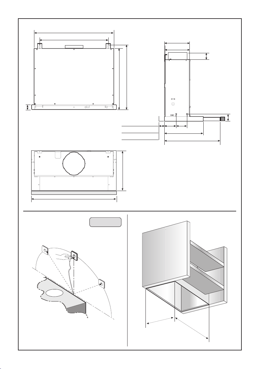
Prima di procedere con l’ installazione dell’ apparecchio effettuare
le seguenti operazioni:
- Per una più facile manovrabilità dell’apparecchio disinserire i filtro/
i antigrasso (Fig.2).
- Nel caso in cui il prodotto sia in versione filtrante togliere i filtri a
cassetta tirando verso l’esterno la leva H come indicato in (fig. 3).
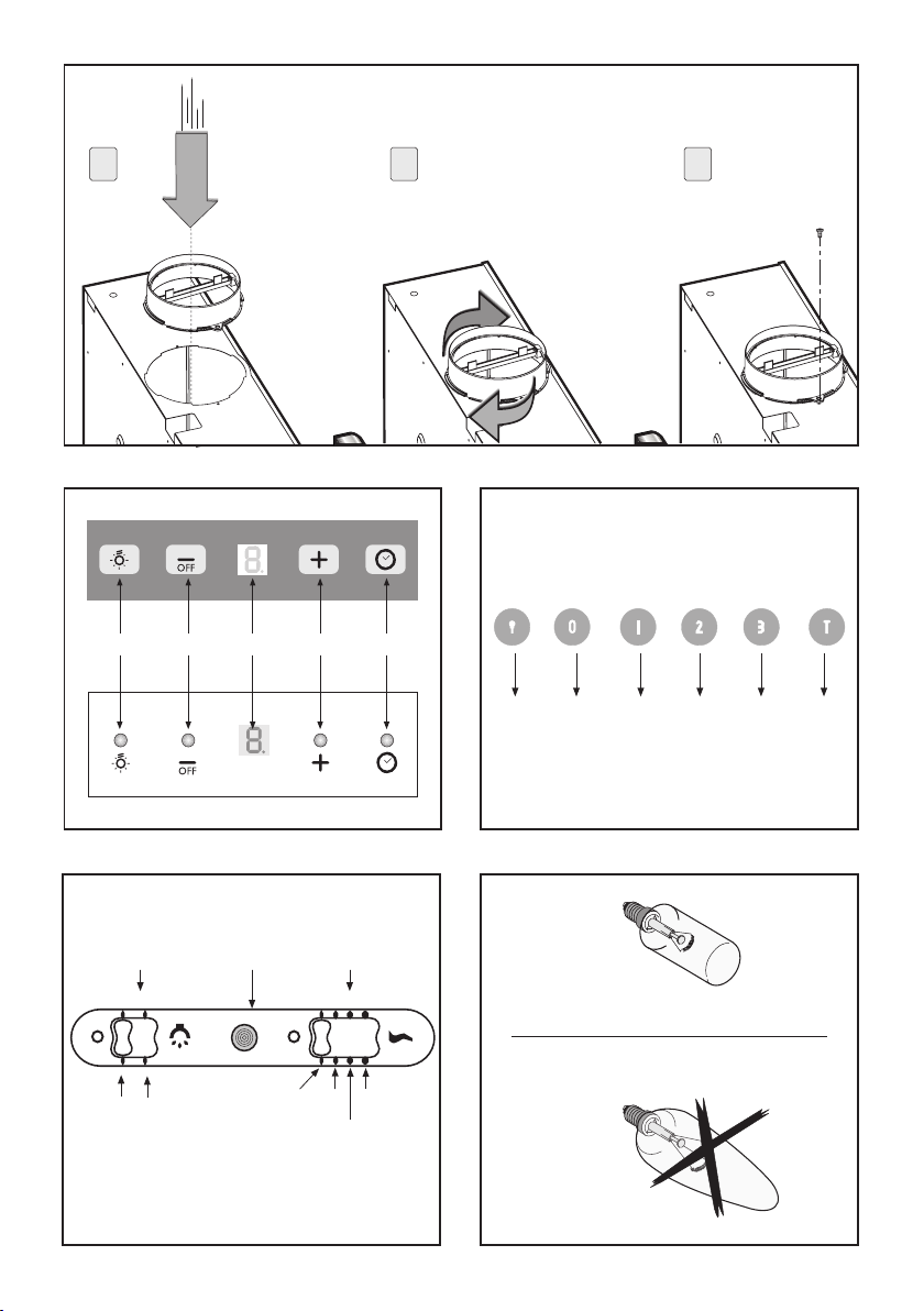
- Montare la flangia sul foro di evaquazione aria ruotando fino allo
scatto di arresto e fissata con una vite (fig 10).
- Nel caso di montaggio dell’apparecchio in versione aspirante
predisporre il foro di evacuazione aria.
(*) Attenzione: montaggio del distanziere in plastica.
Questo prodotto può essere fornito anche con un distanziere in plastica O
che va montato prima dell’ installazione della cappa (fig.7).
Fissare il distanziere alla cappa con le viti P (fig.7).
Per il corretto montaggio, allineare il frontale della cappa al pensile e
decidere la distanza necessaria per chiudere l’eventuale spazio
rimanente tra cappa e parete.
Una volta decisa la distanza prendere un taglierino e togliere il pezzo
in plastica in eccesso (fig.7).
Questo prodotto può essere installato in 2 modi differenti:
Installazione di tipo A figura 4
- Montaggio della cappa nella parte inferiore del pensile
Installazione di tipo B figura 5
- Montaggio della cappa alla parete
- Montaggio della cappa nella parte inferiore del pensile (Fig.4A)
1. Utilizzando l’apposita maschera di foratura effettuare sulle pareti
del pensile n°2 fori E in corispondenza dei ganci D(fig.4).
Posizionare la cappa all’interno, in modo che i ganci laterali Dinterni
si incastrino nei due fori E.
2. Fissarla definitivamente utilizzando 4 viti Bidonee al tipo di mobile
come indicato nella figura 4.
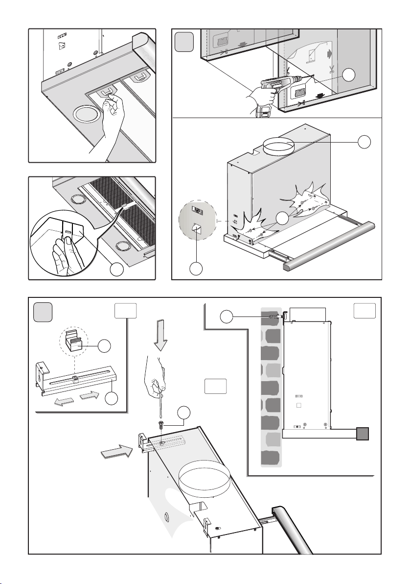
- Montaggio della cappa alla parete (Fig. 5B)
1. Utilizzando l’apposita maschera di foratura effettuare 2 fori di fis-
saggio rispettando le quote indicate.
Per i vari montaggi utilizzare viti e tasselli ad espansione idonei al tipo
di muro (es. cemento armato, cartongesso, ecc). Nel caso in cui le viti
e i tasselli siano forniti in dotazione con il prodotto accertarsi che siano
idonei per il tipo di parete in cui deve essere fissata la cappa.
Regolare la posizione delle staffe M in base alla profondità del pensile
tramite il dado in gabbia N come indicato nella figura 5A.
2. Fissare la cappa alla staffa con la vite G come indicato in figura 5B.
3. Fissare definitivamente la cappa al muro tramite le 2 viti R(fig. 5C).
- Montaggio dei distanzieri
In base al modello che si possiede utilizzare le seguenti istruzioni
d’installazione:
1. distanziere I (fig.6) .
Per chiudere l’eventuale spazio rimanente tra cappa e parete basta
posizionare il distanziere Ia battuta con la parete e fissarlo con le 3 viti
Lcome indicato in figura 6.
ITALIANO I

- 8 -
2. distanziere O (fig.7).
vedi nota (*) Attenzione: montaggio del distanziere in plastica
•VERSIONE ASPIRANTE
Con questo tipo d’installazione l’apparecchio scarica i vapori all’esterno
attraverso una parete perimetrale o canalizzazione esistente. E’
necessario a tal scopo acquistare, un tubo evaquazione aria del tipo
previsto dalle vigenti normative non infiammabile e collegarlo alla
flangia Fin dotazione (fig.8).
• VERSIONE FILTRANTE
Per trasformare la cappa da versione aspirante a versione filtrante,
richiedere al vostro rivenditore i filtri a carbone attivo.
L’ aria viene rimessa nell’ambiente attraverso un tubo di connessione
passante attraverso il mobile e collegato alla flangia F (fig.9).
I filtri al carbone attivo devono essere applicati all’interno della cappa.
Per la sostituzione bisogna tirare verso l’esterno la leva H come
indicato in (fig. 3).
USO E MANUTENZIONE
• Si raccomanda di mettere in funzione l'apparecchio prima di
procedere alla cottura di un qualsiasi alimento. Si raccamanda di lasciar
funzionare l'apparecchio per 15 minuti dopo aver terminato la cottura
dei cibi, per un'evacuazione completa dell'aria viziata.
Ilbuonfunzionamentodellacappaècondizionatodaunacorrettae
costantemanutenzione;unaparticolareattenzionedeveesseredataal
filtroantigrassoeal filtro al carbone attivo.
•Il filtro antigrasso hail compito di trattenerele particelle grasse in
sospensionenell’aria,pertantoèsoggettoadintasarsiintempi variabili
relativamenteall’usodell’apparecchio.
Ilfiltroacrilico,chesitrovaappoggiatoallagriglia,vasostituitoquando
lescritte,visibili attraverso la griglia, cambiano coloreel'inchiostro
siespande;il nuovo filtro deve essereapplicatoin modo tale che le
scrittesianovisibili attraverso la griglia dall'esterno della cappa.
Nel caso in cui i filtri acrilici non abbiano le scritte, oppure siano
presenti filtri metallici o a pannello in alluminio, per prevenire il
pericolodi eventuali incendi, al massimoogni 2 mesi è necessario
lavareifiltrieseguendoleseguentioperazioni:
- togliereilfiltrodallagrigliaelavarloconunasoluzionediacquae
detergenteliquidoneutrolasciandorinvenire lo sporco.
- Sciacquare abbondantemente con acqua tiepida e lasciare
asciugare.
Ifiltrimetallicie/opannelloinalluminiopossonoesserelavatianche
in lavastoviglie. Dopo alcuni lavaggi, se i filtri sono in alluminio o
pannelloinalluminio,sipossonoverificaredellealterazioni delcolore.
Questofattonondà dirittoareclamoperl'eventualeloro sostituzione.
Incasodiinadempienza delleistruzionidisostituzioneedi lavaggiosi
puòverificare il rischio di incendio deifiltriantigrasso.
•Ifiltrialcarbone attivoservonoperdepurarel'ariacheviene rimessa
nell'ambiente.Ifiltrinonsonolavabiliorigenerabiliedevonoessere
sostituitiogniquattromesi al massimo. La saturazione del carbone
attivodipendedall'usopiùomenoprolungatodell'apparecchio,daltipo
dicucinaedallaregolaritàconcuivieneeffettuatalapuliziadelfiltro
antigrasso
• Pulire frequentemente tutti i depositi sul ventilatore e sulle altre
superfici,usandoun pannoinumiditoconalcool denaturatoodetersivi
liquidineutrinonabrasivi.
• L’impianto di illuminazione è progettato per l’uso durante la cottura
e non per l’uso prolungato di illuminazione generale dell’ambiente.
L’uso prolungato dell’illuminazione diminuisce notevolmete la durata
media delle lampade.
COMANDI (Fig.11):
Tasto A = accende/spegne le luci
Tasto B = accende/spegne la cappa.L’apparecchio si accende alla 1°
velocità. Se la cappa è accesa premere il tasto per 2 sec. per spegnere.
Se la cappa si trova alla 1° velocità non è necessario tenere premuto
il tasto per spegnere. Diminuisce la velocità del motore.
Display C = indica la velocità del motore selezionata e l’attivazione
del timer.
Tasto D = accende la cappa.Aumenta la velocità del motore.Premendo
il tasto dalla 3° velocità si inserisce la funzione intensiva per 10’, poi
l’apparecchio ritorna a funzionare alla velocità di esercizio al momento
dell’attivazione. Durante questa funzione il display lampeggia.
Tasto E = IlTimer temporizza le funzioni, al momento dell’attivazione,
per 15 minuti dopo di che queste vengono spente. Il Timer si disattiva
ripremendo il tasto E. Quando la funzione Timer è attiva sul display
deve lampeggiare il punto decimale. Se è in funzione la velocità intensiva
il Timer non si può attivare.
Premendo il tasto Eper 2 secondi, quando l’apparecchio è spento, si
attiva la funzione “clean air”.Questa accende il motore per 10 minuti
ogni ora alla prima velocità. Durante il funzionamento il display deve
visualizzare un movimento rotatorio dei segmenti periferici.Trascorso
questo tempo il motore si spegne e il display deve visualizzare la
lettera “C” fissa fino a quando dopo altri 50 minuti il motore riparte per
altri 10 minuti e così via. Per ritornare al funzionamento normale
premere qualsiasi tasto tranne quello delle luci. Per disattivare la
funzione premere il tasto E.
• COMANDI:
- LUMINOSI (Fig.12) la simbologia è di seguito riportata:
A= tasto ILLUMINAZIONE
B= tasto OFF
C= tasto PRIMA VELOCITA’
D= tasto SECONDA VELOCITA’
E= tastoTERZAVELOCITA’
F= tastoTIMER ARRESTO AUTOMATICO 15 minuti (*)
Se il vostro apprecchio è provvisto della funzione velocità INTENSIVA,
tenere premuto per 2 secondi circa il tasto Ee questa verrà attivata per
10 minuti dopo di che ritornerà alla velocità precedentemente impostata.
Quando la funzione è attiva il LED lampeggia. Per interromperla prima
dei 10 minuti premere di nuovo il tasto E
Premendo il tasto Fper 2 secondi (a cappa spenta) si attiva la funzione
“clean air”. Questa funzione fa accendere il motore per 10 minuti ogni
ora alla prima velocità. Appena attivata la funzione, il motore parte
alla 1° velocità per la durata di 10 minuti durante i quali devono lam-
peggiare contemporaneamente il tasto F e il tasto C.Trascorso questo
tempo il motore si spegne ed il led del tasto F rimane acceso di luce
fissa fino a quando dopo altri 50 minuti riparte il motore alla prima
velocità e i led F e Cricominciano a lampeggiare per 10 minuti e così
via. Premendo qualsiasi tasto ad esclusione delle luci la cappa torna
al suo funzionamento normale immediatamente (es. se premo il tasto
D si disattiva la funzione “clean air” e il motore va subito alla 2° ve-
locità; premendo il tasto B la funzione si disattiva)
(*) La funzione “TIMER ARRESTO AUTOMATICO” ritarda l’arresto
della cappa, che continuerà a funzionare alla velocità d’esercizio in
corso al momento dell’accensione di questa funzione, di 15 minuti.
• Saturazione filtri Antigrasso/Carbone attivo:
- Quando il tasto A lampeggia con una frequenza di 2 sec. i filtri
antigrasso devono essere lavati.
- Quando il tasto A lampeggia con una frequenza di 0,5 sec. i filtri
carbone devono essere sostituiti.
Una volta ricollocato il filtro pulito bisogna resettare la memoria
elettronica premendo il tasto A per circa 5 sec. fino a che termina di
lampeggiare.
• COMANDI: (Fig.13) SLIDER la simbologia è di seguito riportata:
A = Interruttore luce
A1 = tasto Off
A2 = tasto On
B= tasto Gemma spia
C = Controllo di velocità
C1 = tasto Off
C2 = tasto PRIMA VELOCITA’
C3 = tasto SECONDA VELOCITA’
C4 = tasto TERZA VELOCITA’
SI DECLINA OGNI RESPONSABILITA' PER EVENTUALI DANNI
PROVOCATI DALLA INOSSERVANZA DELLE SUDDETTE
AVVERTENZE

- 9 -
ALLGEMEINES
Diese Anleitung bitte aufmerksam durchlesen, da sie wichtige
Sicherheitshinweise zur Installation, zum Gebrauch und zur Wartung
enthält. Die Anleitung für eventuelle zukünftige Konsultationen
aufbewahren. Das Gerät wurde zum Gebrauch in Aspirationsversion
(Luftausscheidung nach außen ), Fitrationsversion (innerer Luftumlauf)
oder mit äußerem Motor entworfen.
SICHERHEITSHINWEISE
1.Vorsicht ist geboten, wenn gleichzeitig eine Abzugshaube und ein
raumluftabhängiger Boiler oder ein offenes Feuer in Betrieb sind, die
von einer anderen Energiequelle als Strom versorgt werden, da die
Küchenhaube die Raumluft absaugt, die auch der Boiler oder das Feuer
zur Verbrennung benötigen. Der Unterdruck im Raum darf denWert
von 4 Pa (4x10 -5 bar) nicht übersteigen. Um einen sicheren Betrieb
der Abzugshaube zu gewährleisten, ist daher immer auf eine
ausreichende Belüftung des Raumes zu achten. Bei der Ableitung der
Luft nach aussen müssen die nationalen Vorschriften eingehalten
werden.
Vor Anschluss des Modells an das Stromnetz :
- kontrollieren Sie dasTypenschild an der Geräteinnenseite um sich
zu vergewissern, ob Spannung und Stromstärke der des Stromnetzes
entsprechen und die Steckdose geeignet ist. Im Zweifelsfall wenden
Sie sich bitte an einen qualifizierten Elektriker.
- Sollte das Speisekabel beschädigt sein, ist es durch ein anderes -
beim Hersteller oder dessen Kundendienst erhältliches - Kabel oder
mit einem speziellen Bausatz - zu ersetzen.
2. ACHTUNG !
Elektrogeräte können unter gewissen Umständen gefährlich sein!
A) Niemals die Filter kontrollieren, wenn die Küchenhaube in
Betrieb ist.
B) Die Lampen und den umliegenden Bereich nicht während
oder nach längerer Benützung der Beleuchtungskörper
berühren.
C) Es ist verboten, Speisen unter der Abzugshaube zu
flambieren.
D) Offene Flammen sind unbedingt zu vermeiden, da diese die
Filter beschädigen und einen Brand verursachen können.
E) Beim Frittieren sind die Speisen ständig zu kontrollieren,
um die Entzündung des Öls zu vermeiden.
F) Wird das Netzkabel dieser Haube beschädigt, muss es in
einer vom Hersteller zugelassenenWerkstatt ersetzt werden,
da hierzu Spezialwerkzeug benöetigt wird.
G) Vor jeglichenWartungsarbeiten unbedingt den Netzstecker
aus der Steckdose entfernen.
Dieses Gerät ist gemäß der EU-Richtlinie 2002/96/EC, Waste
Electrical Electronic Equipment (WEEE) gekennzeichnet. Sorgen Sie
bitte dafür, dass das Gerät korrekt entsorgt wird, der Benutzer trägt
dazu bei, den potentiellen negativen Folgen für Umwelt und Gesundheit
vorzubeugen.
Das auf dem Produkt oder auf den Begleitpapieren befindliche Symbol
sagt aus, dass dieses Produkt nicht wie normaler Hausmüll
behandelt werden darf, sondern dass es einer geeigneten Sammelstelle
für das Recycling der elektrischen und elektronischen Geräteteile
zugeführt werden muss. Entsorgen Sie bitte das Altgerät gemäß der
lokalen Richtlinien. Für weitere Informationen hinsichtlich der
Behandlung, der Wiederverwertung und des Recycling des Produkts
wenden Sie sich bitte an die zuständige lokale Stelle, an die
Sammelstelle für Hausmüll, oder an den Händler, bei dem Sie das
Gerät erworben haben.
INSTALLATIONSANLEITUNG
Montage und Anschluss müssen von einem Fachmann durchgeführt
werden.
• Elektroanschluss
Die Küchenhaube gehört zur Geräteklasse II, daher muss keine der
Leitungen geerdet werden. Der Anschluss an das Stromnetz ist
folgendermassen durchzuführen:
BRAUN = LLeitung
BLAU = Neutrale Linie
Falls nicht vorhanden, muss ein Normstecker mit den auf demTypen-
schild angegebenen Werten an das Kabel angeschlossen werden. Wenn
die Küchenhaube mit einem Netzstecker ausgestattet ist, muss diese
so installiert werden, dass der Stecker gut zugänglich ist.
Beim Direktanschluss an das Stromnetz muss zwischen Gerät und
Netz ein der Netzlast und den geltendenVorschriften entsprechender
Mehrpolstecker mit einer Mindestöffnung von 3 mm zwischen den
Kontakten installiert werden.
• Der Mindestabstand zwischen der Stellfläche für die Kochbehälter
auf der Kochvorrichtung und dem unteren Teil der Abzugshaube muss
mindestens 65 cm betragen.
Falls einVerbindungsrohr verwendet wird, das aus zwei oder mehr
Teilen zusammengesetzt ist, muss der obere Teil über den unteren
gestülpt werden. Auf keinen Fall darf das Abluftrohr der Küchenhaube
an ein Rohr angeschlossen werden, in dem Warmluft zirkuliert oder
das zur Entlüftung von Geräten verwendet wird, die an eine andere
Energiequelle als an Strom angeschlossen sind.
Bevor Sie mit der Installation des Gerätes beginnen, sind folgende
Arbeitsschritte durchzuführen:
- Zur leichteren Handhabung des Gerätes raten wir, den/die Fettfilter
abzunehmen (Abb. 2).
- Sollte es sich bei dem Gerät um ein Umluftgerät, d.h. ein Gerät, das
in Filterversion betrieben wird, handeln, nehmen Sie die Filtereinsätze
ab. Ziehen Sie hierzu den Hebel Hnach vorne. (Abb.3)
- Montieren Sie den Flansch (durch Drehen, bis er hörbar einrastet)
auf das Abluftrohr, und befestigen Sie ihn mit einer Schraube. (Abb.10)
Sollte das Gerät mit Abzugsvorrichtung montiert werden, bereiten Sie
eine Luftabzugsöffnung vor.
(*) Achtung: Montage des Abstandsstücks aus Kunststoff
Dieses Erzeugnis kann auch mit einem Abstandsstück aus Kunststoff
Ogeliefert werden, welches vor der Installation der Dunstabzugshaube
anzubringen ist. (Abb.7)
Befestigen Sie das Abstandsstück mit den Schrauben P.(Abb.7)
Zur ordnungsgemäßen Montage richten Sie das Frontteil der Haube
bündig mit dem Hängeschrank aus und errechnen Sie den erforderlichen
Abstand, um den eventuellen Freiraum zwischen Dunstabzugshaube
und Wand zu schließen.
Nach Festsetzung des korrekten Abstandes schneiden Sie das
überstehende Kunststoffteil mit einem Cutter ab. (Abb.7)
Dieses Gerät kann auf 2verschiedene Arten installiert werden:
Installation des Typs AAbbildung 4
- Montage der Dunstabzugshaube unter einem Hängeschrank
Installation des Typs BAbbildung 5
- Montage der Dunstabzugshaube an derWand
- Montage der Dunstabzugshaube unter einem Hängeschrank
(Abb.4A)
1. Bohren Sie unter Zuhilfenahme der entsprechenden Bohrschablone
2 Löcher Ein die Wände des Hängeschranks und zwar in
Übereinstimmung mit den Haken D.(Abb.4)
Setzen Sie die Dunstabzugshaube ein, und zwar so, dass die beiden
(internen) seitlichen Haken Din die beiden Bohrlöcher Eeinrasten.
2. Befestigen Sie das Gerät nun definitiv mit den für die Schrankart
geeigneten 4 Schrauben B. Siehe hierzu die Abbildung 4.
- Montage der Dunstabzugshaube an derWand (Abb.5B)
1. Bohren Sie unter Berücksichtung der angegebenen Höhen und unter
Zuhilfenahme der entsprechenden Bohrschablone die 2 zur Befestigung
dienenden Löcher.
Verwenden Sie zur Geräteinstallation Schrauben und Dübel, die für die
jeweilige Wandart (zum Beispiel: Betonwände, Wände aus Gipspappe
usw.) geeignet sind. Sollten die Schrauben und Dübel als
Geräteausstattung mitgeliefert werden, stellen Sie bitte sicher, dass
diese für die Art der Wand, an die das Gerät montiert werden soll,
geeignet sind. Richten Sie die Stellung der Bügel Mmittels der
Käfigmutter Ngemäß der Tiefe des Hängeschrankes, so wie auf der
Abbildung 5A veranschaulicht, aus.
2. Befestigen Sie die Haube unter Einsatz der Schrauben G gemäß der
Abbildung 5B an dem Bügel.
3. Befestigen Sie das Gerät nun definitiv mit den 2 Schrauben Ran der
Wand. (Abb. 5C).
- Montage der Abstandsstücke
Befolgen Sie die nachfolgenden Installationsanweisungen unter
Berücksichtung des Modells, das Sie besitzen.
DEUTSCH D

- 10 -
1. Abstandstück I(Abb.6)
Positionieren Sie das Abstandsstück I bis zum Anschlag an der Wand,
um den eventuellen zwischen Haube und Wand frei gebliebenen Raum
zu schließen, und befestigen Sie es, wie auf der Abbildung 6
veranschaulicht, mit den 3Schrauben L.
2. Abstandstück O(Abb.7)
siehe Anmerkung (*) Achtung: Montage des Abstandsstücks aus
Kunststoff
• ABLUFTVERSION
Bei dieser Installationsart führt das Gerät die Kochdünste über eine
Außenwand, oder einen bereits vorhandenen Abluftschacht ins Freie
ab. Besorgen Sie sich zu diesem Zweck ein den geltenden
Bestimmungen entsprechendes, nicht brennbares Abluftrohr und
schließen Sie dieses an den mitgelieferten Flansch Fan. (Abb. 8)
• UMLUFTVERSION
Möchten Sie das Gerät von Abluftversion auf Umluftversion umrüsten,
sind Aktivkohlefilter erforderlich, die Sie bei Ihrem Händler erwerben
können.Die gefilterte Luft wird über ein Verbindungsrohr, das durch
den Schrank hindurch geführt und an den Flansch Fangeschlossen
wird, in den Raum zurückgeführt. (Abb.9)
Die Aktivkohlefilter müssen im Innern der Dunstabzugshaube
angebracht werden.
Um diese auszutauschen ziehen Sie den Hebel Hnach außen. (Abb.3)
BENUTZUNG UND WARTUNG
• Es wird empfohlen, die Küchenhaube schon vor sämtlichen Kochvor-
gängen der Speisen einzuschalten.
Es wir weiterhin empfohlen, das Gerät nach Beendigung des Kochvor-
ganges noch 15 Minuten weiterlaufen zu lassen, um die vollständige
Entlüftung der Kochdämpfe zu gewährleisten. Das einwandfreie Funk-
tionieren der Küchenhaube hängt entscheidend von der Sorgfalt ab, mit
der die Wartungsarbeiten durchgeführt werden, insbesondere die des
Fettfilters und die des Aktivkohlefilters.
• Die Fettfilter haben die Aufgabe, die Fettpartikel in der Abluft zu bin-
den; die Stärke derVerschmutzung hängt daher von der Häufigkeit des
Gebrauchs der Küchenhaube ab. Um eine mögliche Brandgefahr zu
verhindern, muss der Filter in jedem Fall spätestens alle zwei Monate
auf die folgende Weise gereinigt werden:
- Der Abzugshaube die Filter entnehmen und mit Wasser und einem
flüssigen Neutralreiniger abwaschen. Wenn notwendig, einweichen
lassen.
- Dann gründlich mit lauwarmem Wasser abspülen und abtrocknen
lassen.
- Die Filter können auch in der Geschirrspülmaschine gewaschen
werden. Nach mehrmaligem Waschen der Aluminiumfilter können
Farbveränderungen auftreten. Daraus resultiert jedoch kein Anspruch
auf einen kostenlosen Ersatz der Paneele.
• Die Aktivkohlefilter dienen dazu, die Luft zu reinigen, die wieder in
den Raum zurückgeführt wird. Die Filter sind weder waschbar noch
wiederverwertbar und müssen spätestens alle vier Monate ausge-
wechselt werden. Die Sättigung der Aktivkohle hängt ab von der mehr
oder minder langen Benutzungsdauer der Küchenhaube, von der Art
der zubereiteten Speisen und von der Regelmässigkeit, mit der die
Reinigung des Fettfilters durchgeführt wird.
• Alle auf dem Lüftergehäuse und den anderen Teilen der Haube ange-
sammelten Rückstände sind regelmässig mit Spiritus oder neutralem
Flüessigkeitsreiniger ohne Scheuermittel zu entfernen.
• Die Beleuchtung der Dunstabzugshaube sind geplant um während
dem Kochvorgang gebraucht zu werden. Sie sind nicht vorgesehen um
als generelle Beleuchtung zu dienen und vor allem für eine lang dauern-
ende Beleuchtung; in diesem Falle könnten Sie durchbrennen. Aus
diesem Grund schalten Sie bitte das Licht aus am Ende des Kochvor-
gangs.
BEDIENUNG: (Abb.11)
TTaste A = schaltet die Beleuchtung ein/aus.
Taste B = schaltet die Haube ein/aus.Das Gerät schaltet sich in der
ersten Saugstärke ein.Wenn die Haube eingeschaltet ist, dieTaste
eine halbe Sekunde lang drücken, um sie abzuschalten. Ist die Haube
in der ersten Saugstärke eingeschaltet, ist es zum Abschalten nicht
erforderlich, dieTaste zu drücken.Verringert die Geschwindigkeit des
Motors.
Display C = zeigt die gewählte Motorgeschwindigkeit und die Aktivie-
rung der Timer-Funktion an.
Taste D = schaltet die Haube ein.Erhöht die Geschwindigkeit des
Motors. Wenn man, während die Haube in Betrieb ist, auf die 3° Ge-
schwindigkeit drückt, stellt sich für 10 Minuten automatisch die “Inten-
siv-Stufe” ein, dann geht die Haube wieder auf die Geschwindigkeit
zurück, welche vorher in Betrieb war. Während der Funktion “Inten-
siv-Stufe” leuchtet das Display auf.
Taste E = DerTimer steuert die Zeit der Funktionen. Ab der Aktivierung
derTaste bleiben diese für 15 Minuten eingeschaltet und werden dann
ausgeschaltet.DerTimer kann durch erneuten Druck auf dieTaste E
deaktiviert werden. Bei aktivierter Timer-Funktion muss auf dem
Display der Dezimalpunkt auf Blinklicht geschaltet sein. Befindet sich
die Dunstabzugshaube auf Intensivstufe, kann der Timer nicht aktiviert
werden.
Wird bei ausgeschaltetem Gerät dieTaste Efür 2 Sekunden gedrückt,
wird die Funktion "Clean Air" aktiviert. Diese bewirkt das Einschalten
des Motors für 10 Minuten jede Stunde auf der ersten Leistungsstufe.
Während dieser Funktionsweise muss auf dem Display eine
Rotationsbewegungder peripheren Segmente angezeigt sein. NachAblauf
dieser Zeit schaltet der Motor ab und auf dem Display muss die Fix-
Anzeige des Buchstaben "C" ersichtlich sein, und zwar so lange, bis nach
weiteren 50 Minuten der Motor erneut für 10 Minuten startet, und so weiter.
• BEDIENUNG: DER BELEUCHTUNG (Abb.12) die
SimboLbezeichnungen sind folgend wiedergegeben:
A=Taste BELEUCHTUNG
B= Taste OFF
C = Taste ERSTE GESCHWINDIGKEIT
D = Taste ZWEITE GESCHWINDIGKEIT
E= Taste DRITTE GESCHWINDIGKEIT
F =TIMER AUTOMATISCHES ANHALTEN nach 15 Minuten (*)
•Wenn Ihr Gerät mit der Funktion INTENSIVE Geschwindigkeit
ausgestattet ist, etwa zwei Sekunden lang dieTaste Edrücken, dann
wird diese aktiviert (dann wird diese) 10 Minuten lang aktiviert, danach
kehrt es zu der zuvor eingestellten Geschwindigkeit zurück.
Wenn die Funktion aktiv ist, blinkt die LED.Um sie vor Ablauf der 10
Minuten zu unterbrechen, wieder dieTaste Edrücken.
•Wenn die Taste Fzwei Sekunden lang gedrückt wird (bei ausge-
schalteter Haube), wird die Funktion “clean air”aktiviert.Diese Funk-
tion bewirkt das Anschalten des Motors für 10 Minuten pro Stunde mit
der ersten Geschwindigkeit. Sofort nach der Aktivierung der Funktion
startet der Motor mit der 1. Geschwindigkeit für die Dauer von 10
Minuten, während dieser Zeit müssen dieTaste F und die Taste C
gleichzeitig blinken. Nach Ablaufen dieser Zeit geht der Motor aus, und
die Led derTaste F leuchtet fest weiter, bis der Motor nach weiteren 50
Minuten mit der ersten Geschwindigkeit neu startet und die Leds F und
Cwieder anfangen, 10 Minuten lang zu blinken, und so weiter. Durch
Drücken jeder beliebigenTaste außer den Lichtern kehrt die Haube
sofort zu ihrem normalen Funktionieren zurück (Beispiel: Wenn ich
die Taste D drücke, wird die Funktion “clean air” deaktiviert, und der
Motor geht sofort in die 2.Geschwindigkeit;wenn die Taste B gedrückt
wird, wird die Funktion deaktiviert)
(*) Die Funktion "Timer automatisches Anhalten" verzögert das An-
halten der Haube, die 15 Minuten mit der zum Zeitpunkt der Einschal-
tung dieser Funktion gewählten Betriebsgeschwindigkeit weiterläuft.
• Sättigung der Fett- und Aktivkohlefilter:
- Leuchtet dieTaste Aalle 2 Sek. auf, müssen die Fettfilter gereinigt
werden.
- Leuchtet die Taste Aalle 0,5 Sek. auf, müssen die Kohlefilter
ausgetauscht werden.
Nachdem der gesäuberte Filter wieder eingesetzt wurde, muss der
elektronische Speicher neu aktiviert werden, indem man dieTaste A
für circa 5 Sek. gedrückt hält bis diese aufhört zu blinken.
• BEDIENUNG: (Fig.13) SLIDER die SimboLbezeichnungen sind
folgend wiedergegeben:
A = Lichtschalter
A1 = Aus-Taste
A2 = Ein-Taste
B=Taste Kontrollleuchte Gemma
C = Geschwindigkeitskontrolle
C1 = Aus-Taste
C2 =Taste ERSTE GESCHWINDIGKEIT
C3 =Taste ZWEITE GESCHWINDIGKEIT
C4 = Taste DRITTE GESCHWINDIGKEIT
FÜR SCHÄDEN, DIE AUF DIE NICHTBEACHTUNG DER OBEN
GENANNTEN ANWEISUNGEN ZURUCKZUFÜHREN SIND,
WIRD KEINERLEI VERANTWORTUNG ÜBERNOMMEN.
- 11 -
AZUL = N neutro.
Si no está incluido, monte en el cable un enchufe normalizado para la
carga indicada en la etiqueta de las caracteristicas. Si está provista de
enchufe,coloque la campana de tal manera que el enchufe quede en un
sitio accesible. En caso de conexión directa a la corriente eléctrica, es
necesario interponer entre el aparato y la red un interruptor omnipolar
con abertura mínima de 3mm, adecuado a la carga y que responda a
las normas vigentes.
• La distancia mínima entre la superficie de soporte de los recipientes
de cocción en el dispositivo de cocción y la parte más baja de la
campana de cocina debe de al menos 65 cm. Si debe usarse un tubo
de conexión compuesto de dos o más partes, la parte superior debe
estar fuera de la parte inferior. No conecte la descarga de la campana
a un conducto en el que circúle airecaliente o que sea utilizado para
evacuar los humos de aparatos alimentados por una energía que no
sea eléctrica.
Antes de instalar el aparato efectúe las siguientes operaciones:
- Para que sea más fácil maniobrar el aparato, desconecte los filtros
antigrasa (Fig. 2).
- Si la versión del producto es filtrante, quite los filtros de caja, tirando
hacia afuera la palanca H, como se indica en la fig. 3.
- Instale la brida en el orificio de evacuación del aire girándola hasta
el tope y fijándola con un tornillo (fig. 10).
En el caso de montaje del aparato en la versión aspirante, predisponer
el orificio de evacuación aire.
(*) Atención: montaje del distanciador de plástico.
Este producto se puede suministrar también con un distanciador de
plástico Oque se coloca antes de instalar la campana (fig. 7).
Fije el distanciador a la campana con los tornillos P(fig. 7).
Para el correcto montaje, alinee la parte delantera de la campana con
el armario colgante, entre la campana y la pared queda una distancia
que deberá cerrarse con un distanciador.
Una vez decidida la distancia, quite la parte de plástico en exceso con
una cizalla (fig. 7).
Este producto se puede instalar de 2 modos diferentes:
Instalación de tipo Afigura 4
- Instalación de la campana en la parte inferior del armario
colgante
Instalación de tipo Bfigura 5
- Instalación de la campana en la pared
- Instalación de la campana en la parte inferior del armario
colgante (Fig. 4A)
1. Utilizando la plantilla de perforación correspondiente, realice 2
orificios E en las paredes del armario colgante a la altura de los ganchos
D(fig. 4).
Coloque la campana en el interior, de modo que los ganchos laterales
Dinternos se encastren en los dos orificios E.
2. Fíjela definitivamente utilizando 4 tornillos Badecuados para el tipo
de mueble, como se indica en la figura 4.
- Instalación de la campana en la pared (Fig. 5B)
1. Utilizando la plantilla de perforación correspondiente, realice 2
orificios de fijación respetando las alturas indicadas.
En los distintos montajes utilice tornillos y espigas adecuados para el
tipo de pared (por ej. cemento armado, cartón de yeso, etc.). Cuando
los tornillos y las espigas se suministren con el producto, controle que
sean adecuados para el tipo de pared a la que se debe fijar la campana.
Regule la posición de las abrazaderas Msegún la profundidad del
armario colgante utilizando la tuerca en jaula Ncomo se indica en la
figura 5A.
2. Fije la campana a la abrazadera con el tornillo Gcomo se indica en
la figura 5B.
3. Fija definitivamente la campana a la pared con los 2 tornillos R(fig.
5C).
- Montaje de los distanciadores
Según el modelo que se posee, durante la instalación, aplique las
siguientes instrucciones:
1. distanciador I(fig. 6).
GENERALIDADES
Lea atentamente el contenido del presente libro de instrucciones pues
contiene indicaciones importantes para la seguridad en la instalación,
el uso y el mantenimiento (Consérvelo para un posible consulta pos-
terior). El aparato ha sido diseñado para el uso en versión aspiradora
(evacuación de aire hacia el exterior ), filtrante (reciclaje del aire en
el interior) o con motor exterior.
SUGERENCIAS PARA LA SEGURIDAD
1.Preste atención si funcionan contemporáneamente una campana
aspirante y un quemador o una chimenea que toman el aire del am-
biente y están alimentados por energía que no sea eléctrica, pues la
campana aspirante toma del ambiente el aire que el quemador o la
chimenea necesitan para la combustión. La presión negativa del local
no debe superar los 4 Pa (4x10 -5 bares). Para un funcionamiento
seguro, realice primero una adecuada ventilación del local. Para la
evacuación externa, aténgase a las disposiciones vigentes en su país.
Antes de enchufar el modelo a la corriente eléctrica:
- controlar los datos de matrícula (que se encuentran en el interior del
aparato) para constatar que la tensión y la potencia correspondan a la
de la red y el enchufe de conexión sea idóneo. En caso de dudas,
recurra a un electricista calificado.
- Si el cable de alimentación está dañado, se debe cambiar con un
cable o conjunto especial de cables que puede suministrar tanto el
fabricante como el servicio de asistencia técnica.
2. ¡ ATENCIÓN !!
En determinadas circunstancias los electrodomésticos pueden ser
peligrosos.
A) No intente controlar los filtros cuando la campana esté fun-
cionando.
B) No tocar las lámparas y las zonas adyacentes, durante e
inmediatamente después del uso prolongado del equipo de
iluminación.
C) Está prohibido cocinar alimentos a la llama debajo de la cam-
pana.
D) Evite las llamas libres, pues resultan perjudiciales para los
filtros y pueden provocar incendios.
E) Controle en todo momento los alimentos fritos para evitar
que el aceite caliente prenda fuego.
F) Antes de realizar cualquier operación de mantenimiento
desconecte la campana de la corriente eléctrica.
Este aparato está fabricado en conformidad con la Norma Europea
2002/96/EC, Waste Electrical and Electronic Equipment (WEEE).
Controlando que este producto sea eliminado de modo correcto, el
usuario contribuye a prevenir consecuencias negativas para el
ambiente y la salud.
El símbolo en el producto o en la documentación adjunta, indica que
este producto no debe ser tratado como residuo doméstico sino que
debe ser entregado a un punto de recolección para reciclar aparatos
eléctricos y electrónicos. Elimínelo siguiendo las normas locales
para la eliminación de desechos. Para mayor información sobre el
tratamiento, recuperación o reciclaje de este producto, llame a la oficina
local encargada, al servicio de recolección de desechos domésticos
o al negocio en el cual ha comprado el producto.
INSTRUCCIONES PARA LA INSTALACIÓN
Las operaciones de montaje y conexión eléctrica deben ser efectuadas
por personal especializado.
• Instalación eléctrica
El aparato está construido en clase II, por lo tanto no se debe e conectar
ningún cable a la toma de tierra.
La conexión a la corriente eléctrica debe realizarse de la siguiente
manera:
MARRÓN = L línea.
ESPAÑOL E

- 12 -
Para cerrar el espacio que queda entre la campana y la pared, basta
colocar el distanciador Ihasta el tope con la pared y fijarlo con los 3
tornillos
Lcomo se indica en la figura 6.
2. distanciador O(fig. 7).
ver la nota (*) Atención: montaje del distanciador de plástico.
• VERSIÓN ASPIRANTE
Con este tipo de instalación, el aparato descarga los vapores al exterior
a través de una pared perimétrica o de una canalización existente. Por
ello, es necesario comprar un tubo de evacuación de aire del tipo
previsto por las normas vigentes, no inflamable, y conectarlo a la brida
Fsuministrada con el aparato (fig. 8).
• VERSIÓN FILTRANTE
Para transformar la campana de la versión aspirante a la versión
filtrante, solicite a su revendedor los filtros de carbón activo.
El aire se devuelve al ambiente por un tubo de conexión que pasa a
través del mueble y está conectado a la brida F(fig. 9).
Los filtros de carbón activo se deben colocar en el interior de la campana.
Para la sustitución, es necesario tirar hacia fuera la palanca Hcomo
se indica en la fig. 3.
USO Y MANTENIMIENTO
• Se aconseja poner en funcionamiento el aparato antes de cocinar
cualquier tipo de alimento.
Se aconseja dejar funcionando el aparato durante 15 minutos después
de haber terminado de coninara los alimentos, para una evacuación
completa del aire viciaco.
El buen funcionamiento de la campana depende de la asiduidad con la
cual se realicen las operaciones de mantenimiento, sobre todo, del
filtro antigrasa, o del filtro al carbón activo.
• Los filtros antigrasa sirven para retener las partículas de grasa en
suspensión en el aire, por lo tanto se pueden obstruir en un espacio que
depende del uso que se haga del aparato.De todas formas para evitar
el peligro de posibles incendios, como máximo cada dos meses es
necesario limpiar el filtro observando las siguientes operaciones:
- Quite los filtros de la campana y lávelos con una solución de agua y
detergente líquido neutro dejando ablandar la suciedad.
- Aclare con abundante agua templada y deje secar.
- Se pueden lavar también los filtros en el lavavajillas
Después de algunos lavados los paneles de aluminio se puede verifi-
car en los paneles de aluminio posibles alteraciones del color. Esto no
da opción a reclamaciones para una posible sustitución de los paneles.
• Los filtros al carbón activo sirven para depurar el aire que volverá
a circular en el ambiente. Los filtros no son lavables o reciclables y
deben ser cambiados máximo cada cuatro meses. La saturación del
carbón activo, depende del uso más o menso prolongado del aparato,
dal tipo de cocina y de la regularidad con la cual se efectúe la limpieza
del filtro antigraso.
• Limpie frecuentemente todos los restos de grasa del ventilador y de
las otras superficies usando un paño humedo con alcohol etílico o
detergentes líquidos neutros no abrasivos.
• La instalación de iluminación ha sido proyectada para ser utilizada
durante la cocción y no para el uso prolongado de iluminación general
del ambiente. Su empleo prolongado disminuye notablemente la
duración media de las lámparas.
MANDOS: (Fig.11)
Botón A = enciende\apaga las luces.
Botón B = enciende\apaga la campana. El aparato pone en marcha
en la 1° velocidad. Si la campana está encendida apriete el botón 2
segundos para apagar. Si la campana está en la 1° velocidad no hay
que apretar el botón para apagar. Disminuye la velocidad del motor.
Display C = indica la velocidad del motor seleccionada y la puesta en
marcha del timer.
Botón D = enciende la campana. Aumenta la velocidad del motor.
Pulsando el pulsador de la tercera velocidad se introduce la función
intensiva por 10 minutos, después el aparado vuelve a funcionar a la
velocidad de ejercicio al momento de la activación. Durante esta fun-
ción el display relampagua.
Botón E = El Timer temporiza las funciones, al momento de la acti-
vación, por 15 minutos después de que se han apagado. El Timer se
desactiva volviendo a oprimir el botón E. Cuando la función Timer está
encendida, en el display debe relampaguear el punto decimal. No se
puede activar si está funcionando la velocidad intensiva del Timer.
Si oprime el botón Epor un par de segundos, mientras el aparato está
apagado, se activa la función “clean air”.Que enciende el motor en la
primera velocidad a 10 minutos por cada hora. Durante el funciona-
miento, se debe visualizar en el display un movimiento giratorio de los
segmentos periféricos. Transcurrido dicho tiempo el motor se apaga,
y se visualiza la letra “C” fija en el display, después de 50 minutos éste
arranca de nuevo por otros 10 minutos y así sucesivamente. Para
regresar al funcionamiento normal apriete cualesquiera de los boto-
nes excepto el de la luz. Para desactivar la función oprima el botón E.
• MANDOS: (Fig.12) Luminosos la simbología es la siguiente:
A= botón ILUMINACION.
B= botón OFF
C= botón PRIMERAVELOCIDAD.
D= botón SEGUENDAVELOCIDAD.
E= botón TERCERA VELOCIDAD.
F= botón TIMER PARADA AUTOMáTICA 15 MINUTOS (*).
•Si su aparato está equipado con la función velocidad INTENSIVA,
tener el botón E presionado por casi 2 segundos para activar esta
función por 10 minutos, pasado este tiempo regresará a la velocidad
precedentemente programada.
Cuando la función es activa el LED relampagea. Para interrumpirla
antes de los 10 minutos presione la tecla Ede nuevo.
Presionando el botón F por dos segundos (con la campana apagada)
se activa la función “clean air”. Esta función enciende el motor por 10
minutos cada hora en la primera velocidad. Apenas sea activada la
función, el motor parte con la 1° velocidad por un período de 10 minu-
tos, durante los cuales deben relampagear los botones F y C
contemporaneamente.Terminado este período el motor se apaga y el
led del botón F se mantiene encendido con una luz fija por 50 minutos.
En ese momento el motor reparte en la primera velocidad, los leds F
y C recomienzan a relampagear por 10 minutos y se repite el ciclo.
Presionando cualquier botón, a excepción de las luces, la campana
inmediatamente regresa a su funcionamiento normal (ej. presionando
el botón D se desactiva la función “clean air” y el motor cambia a la 2°
velocidad; presionando el botón B la función se desactiva).
(*) La función “ timer parada automatica” retarda la parada de la
campana, que continuará a funcionar a la velocidad seleccionada en
el momento del encendido de esta función, 15 minutos.
• Saturación de los filtros antigrasa/carbón activo :
- Cuando el botón Acentellea con una frecuencia de 2 seg., los filtros
antigrasa deben ser lavados.
- Cuando el botón Acentellea con una frecuencia de 0,5 seg., los filtros
de carbón deben ser sustituidos.
Después que se vuelve a colocar el filtro limpio, es necesario reiniciar
la memoria electrónica presionando el botón Adurante 5 seg. hasta
que deje de centellear.
• MANDOS: (Fig.13) SLIDER la simbología es la siguiente:
A = Interruptor luz
A1 = botón Off
A2 = botón On
B = botón Gema indicadora
C= Control de velocidad
C1 = botón Off
C2 = botón PRIMERA VELOCIDAD
C3 = botón SEGUNDA VELOCIDAD
C4 = botón TERCERA VELOCIDAD
EL FABRICANTE NO SE HACE RESPONSABLE DE LOS DA-
ÑOS PRODUCIDOS POR EL INCUMPLIMIENTO DE ESTAS
ADVERTENCIAS.

- 13 -
GÉNERALITÉS
Lire attentivement le contenu du mode d'emploi puisqu'il fournit des
indications importantes concernant la sécurité d'installation, d'emploi
et d'entretien.Le conserver pour d' ultérieures consultations.L’appa-
reil a été conçu pour être utilisé dans le modèle aspirant (évacuation
de l’air à l’extérieur), filtrant (retour de l’air à l’intérieur ) ou doté d’un
moteur externe.
CONSEILS POUR LA SÉCURITÉ
1. Attention, lorsque dans la même pièce vous utilisez simultanément
la hotte à évacuation avec un brûleur ou une cheminée alimentés par
une énergie autre que l'électricité, vous pouvez créer un problème
"d'inversion de flux". Dans ce cas la hotte aspire l'air nécessaire à leur
combustion. La dépression dans le local ne doit pas dépasser les 4 Pa
(4x10 -5 bar). Pour un fonctionnement en toute sécurité, n'oubliez pas
de prévoir une ventilation suffisante du local.
Pour l'évacuation vers l'extérieur, veuillez vous référer aux disposi-
tions en vigueur dans votre pays.
Avant de brancher la hotte au réseau de distribution électrique
:
- lire les données reportées sur la plaquette d’identification (appliquée
à l’intérieur de la hotte) pour vérifier si le voltage et la puissance cor-
respondent à ceux du réseau. Contrôler aussi si la prise est adaptée.
En cas de doutes, contacter un électricien qualifié.
- Si le câble d'alimentation est abîmé, il faut le remplacer par un autre
câble ou par un ensemble, spécialement prévus, que vous pouvez
commander au fabricant ou à un de ses services d'assistance technique.
2. ATTENTION !
Dans des circonstances déterminées les électroménagers peu-
vent être dangereux.
A)Ne pas controler les filtres pendant que la hotte est en fonc-
tionnement
B) Ne pas toucher les lames et les zones adjacentes, pendant et
immediatement apres l’utilisation prolonge du systeme
d’eclairage.
C)Il est interdit de cuire les aliments à la flamme sous la hotte
D)Eviter la flamme libre, parcequ'elle est nuisible pour les filtres
et dangereuse pour les incendies
E)Controler constamment les aliments frits pour éviter que
l'huile surchauffée/ne prenne feu
F)Avant d'effectuer n'importe quel entretien déconnecter la
hotte du réseau électrique.
Cet appareil est marqué conformément à la Directive européenne
2002/96/CE sur les déchets d'équipements électriques et électroniques
(DEEE). Assurez-vous que cet appareil soit mis au rebus selon la
réglementation en vigueur, vous éviterez ainsi des conséquences
néfastes sur l'environnement et la santé.
Le symbole appliqué sur le produit ou sur la documentation jointe
rappelle que cet appareil ne doit pas être traité comme un déchet
domestique mais faire l'objet d'une collecte sélective dans une
déchetterie spécialisée dans le recyclage des appareils électriques et
électroniques. Conformez-vous aux réglementations locales sur la
collecte et l'élimination des déchets. Pour tout autre renseignement
sur le traitement, la récupération et le recyclage de cet appareil, veuillez
contacter le bureau concerné de votre ville, le service de collecte des
déchets domestiques ou le magasin où vous avez acheté votre appareil.
INSTRUCTIONS POUR L'INSTALLATION
Le montage et le branchement électrique doivent être effectués par un
personnel spécialisé.
• Connexion électrique
L'appareil est construit en classe II, pour cela aucun cable ne doit être
connecté avec la prise terre.
La connection avec le réseau électrique doit être éxécutée comme
suit:
MARRON = L ligne
BLEU = Nneutre
Si elle n'a pas été prévue, monter sur le cable une fiche normalisée
pour la charge indiquée sur l'etiquette des caractéristiques. Si elle est
dotée d'une fiche, la hotte doit être installée en sorte que la fiche soit
accessible.
En cas de connection directe avec le réseau électrique, il est néces-
saire d'interposer entre l'appareil et le réseau un interrupteur
omnipolaire avec une ouverture minimale entre les contacts de 3 mm,
proportionnel à la charge et correspondant aux normes en vigueur.
• La distance minimum entre la surface de support des récipients de
cuisson sur le dispositif de cuisson et la partie la plus basse de la hotte
pour cuisine doit être de 65 cm au moins.
S'il doit être utilisé un tuyau de connection composé de deux ou plu-
sieurs parties, la partie superieure doit être à l'exterieur de celle
inférieure.
Ne pas relier le tuyau d'échappement de la hotte à un conduit dans
lequel circule de l'air chaud ou employé pour évacuer les fumées des
appareils alimentés par une énergie differente de celle électrique.
Opérations à effectuer avant d'installer l'appareil :
- Pour une meilleure maniabilité de l'appareil, ôtez le(s) filtre(s) anti-
gras (Fig.2).
- En cas de hotte en version recyclage, retirez les filtres à cassette en
tirant le levier Hvers l'extérieur comme illustré (voir fig. 3).
- Montez la bride sur le trou d'évacuation de l'air en tournant jusqu'au
déclic et fixez-la à l'aide d'une vis (fig 10).
S’il s’agit d’une hotte aspirante, il faudra prévoir une ouverture pour
l’évacuation de l’air.
(*) Attention : montage de l'entretoise en plastique.
Cet article peut être livré avec une entretoise en plastique Oqu'il faut
monter avant d'installer la hotte (fig.7).
Fixez l'entretoise à la hotte à l'aide des vis P(fig.7).
Pour un assemblage correct, procédez à l'alignement du fronton de la
hotte avec le meuble haut et calculez l'épaisseur nécessaire pour boucher
l'espace vide entre la hotte et le mur.
Dès que la distance est fixée, coupez à l'aide d'un cutter le morceau de
plastique excédant (fig.7).
Cet article peut être monté de 2façons différentes :
Installation de type Afigure 4
- Fixation de la hotte sous un meuble haut
Installation de type Bfigure 5
- Fixation murale de la hotte
- Fixation de la hotte sous un meuble haut (Fig.4A)
1. Servez-vous du gabarit de perçage prévu pour percer 2 trous Edans
les parois du meuble au niveau des crochets D(fig.4).
Introduisez la hotte dans le meuble de manière à ce que les crochets
internes latéraux Daillent se loger dans les deux trous E.
2. Fixez-la définitivement à l'aide des 4 vis Bappropriées au type de
meuble comme illustré (voir figure 4).
- Fixation murale de la hotte (Fig. 5B)
1. Servez-vous du gabarit de perçage prévu pour percer 2 trous de
fixation suivant les dimensions indiquées.
Pour les opérations de montage, utilisez des vis et des chevilles
adaptées à la nature du mur (béton armé par ex. ou placoplâtre, etc.).
Si les vis et chevilles sont fournies avec l'appareil, assurez-vous
qu'elles soient bien adaptées à la nature du mur qui supportera la hotte.
Réglez la position des étriers Men fonction de la profondeur du meuble
à l'aide de l'écrou cage Ncomme illustré (voir figure 5A).
2. Fixez la hotte à l'étrier à l'aide de la vis G comme illustré (voir figure
5B).
3. Fixez définitivement la hotte au mur à l'aide des 2 vis R(fig. 5C).
- Installation des entretoises
Conformez-vous aux instructions de montage correspondant à votre
modèle de hotte :
1. entretoise I (fig.6).
FRANÇAIS F

- 14 -
Pour boucher tout espace vide entre la hotte et le mur, il suffit de placer
l'entretoise Icontre le mur et de la fixer à l'aide des 3vis Lcomme
illustré figure 6.
2. entretoise O (fig.7).
voir note (*) Attention : montage de l'entretoise en plastique
•VERSION A EVACUATION
Grâce à ce type d'installation, l'appareil évacue les vapeurs de cuisson
à l'extérieur à travers un mur de l'habitation ou dans un conduit
préexistant. Il faut donc se munir d'un tuyau d'évacuation de l'air non
inflammable, du type préconisé par les normes en vigueur et le
raccorder à la bride Ffournie (fig.8).
• VERSION RECYCLAGE
Pour transformer la hotte de la version à évacuation à la version
recyclage, demandez à votre vendeur des filtres à charbon actif.
L'air est renvoyé dans la pièce à travers un tuyau de connexion passant
à travers le meuble et raccordé à la bride F(fig.9).
Les filtres à charbon actif doivent être installés à l'intérieur de la hotte.
Pour leur remplacement, tirez le levier Hvers l'extérieur comme illustré
(voir fig. 3).
EMPLOI ET ENTRETIEN
• Nous vous recommandons de mettre la hotte en route avant de com-
mencer à cuisiner.
Les filtres doivent être appliqués sur le groupe d'aspiration situé à
l'intérieur de la hotte en les centrant et en les faisant tourner de 90
degrés jusqu'au blocage.
Le bon fonctionnement de la hotte est lié à la fréquence des opérations
d'entretien, et plus particulièrement à l'entretien du filtre anti-graisse
et du filtre au charbon actif.
• Les filtres anti graisse ont pour rôle de retenir les particules grasses
en suspension dans l'air. Ils peuvent donc se boucher plus ou moins
rapidement selon l'usage de la hotte.
Dans tous les cas, pour prévenir un éventuel risque d'incendie, il est
nécessaire de nettoyer au moins tous les deux mois le filtre en suivant
les indications suivantes:
- Retirer les filtres de la hotte et les laver avec de l'eau et un détergent
liquide neutre, laisser la saleté se décoller.
- Rincer abondamment à l'eau tiède et laisser sécher.
- Les filtres peuvent également être lavés dans le lave vaisselle.
Après plusieurs lavages des panneaux en aluminium, on peut consta-
ter un changement de leur couleur. Ceci n'ouvre pas droit à réclama-
tion afin d'obtenir un éventuel changement des panneaux.
• Les filtres au charbon actif servent à filtrer l'air qui sera rejeté dans
la pièce. Les filtres ne sont ni lavables ni régénérables et doivent être
changés tous les trois mois au maximum. La saturation du charbon
actif dépend de l'utilisation plus ou moins prolongée de l'appareil, du
type de cuisine effectué et de la régularité avec laquelle est effectué le
nettoyage du filtre anti graisse.
• Nettoyer fréquemment tous les dépôts sur le ventilateur et les autres
surfaces, en utilisant un chiffon imbibé d'alcool dénaturé ou de déter-
gents liquides neutres non abrasifs.
• L’éclairage de cette hotte est destiné à être utilisé uniquement lorsque
vous cuisinez. Il n’est pas destiné pour une illumination générale et
pour une longue durée; dans ce cas les ampoules peuvent se brûler.
Pourant veuillez éteindre l’éclairage dès que vous avez terminé de
cuisiner.
COMMANDES: (Fig.11)
Touche A = allume/éteint les lumières.
Touche B = allume/éteint la hotte.l’appareil s’allume à la 1° vitesse.
si la hotte est allumée, appuyer sur la touche pendant 2 sec. pour
éteindre. Si la hotte se trouve à la 1° vitesse, il n’est pas nécessaire de
tenir la touche appuyée pour éteintre. Diminue la vitesse du moteur.
Display C = indique la vitesse du moteur sélectionnée et l’activation
du timer.
Touche D = allume la hotte.Augmente la vitesse du moteur.En pressant
la touche de la 3ème vitesse la fonction intensive s’active pendant 10',
puis l’appereil recommance à fonctionner à la vitesse d’exercice au
moment de la première activation. Pendant cette fonction le display
clignote.
Touche E = au moment de l’activation le Minuteur temporise les fonc-
tions pendant 15 minutes, après quoi ces dernières s’éteignent. En
pressant la touche E, le Minuteur se désactive. Quand la fonction
Minuteur est active, le point décimal doit clignoter sur l’écran. Si la
vitesse intensive est en fonction, le Minuteur ne peut être activé.
En pressant la touche E pendant 2 secondes, quand l’appareil est éteint,
la fonction “clean air”s’active.Cette dernière met en marche le mo-
teur chaque heure pendant 10 minutes à la première vitesse. Durant le
fonctionnement l’écran doit visualiser un mouvement rotatif des seg-
ments périphériques. Après quoi le moteur s’éteint et l’écran doit vi-
sualiser la lettre “C” fixe, jusqu’à ce qu’après 50 autres minutes, le
moteur reparte pendant 10 minutes supplémentaires et ainsi de suite.
Pour retourner au fonctionnement normal presser n’importe quelle
touche sauf celle de l’éclairage. Pour désactiver la fonction presser la
touche “E”.
• COMMANDES: (Fig.12) Lumineux le symbole sont le suivant:
A= touche ECLAIRAGE
B= touche OFF
C = touche PREMIERE VITESSE
D = touche DEUXIEME VITESSE
E= touche TROISIEME VITESSE
F = touche MINUTEUR ARRET AUTOMATIQUE 15 minutes (*)
•Si votre appareil possède la fonction vitesse INTENSE, maintenir
appuyé pendant environ 2 secondes le bouton E pour activer la fonction
pendant 10 minutes, après quoi elle retournera à la vitesse établie en
précédence. Quand la fonction est active, la LED clignote. Pour l’inter-
rompre avant les 10 minutes, presser de nouveau sur la touche E.
•En appuyant sur le bouton F pendant 2 secondes (lorsque la hotte est
allumée), la fonction « clean air » s’active. Cette fonction démarre le
moteur pour 10 minutes par heure à la première vitesse.
Dès que la fonction est activée, le moteur démarre en 1ère vitesse pour
10 minutes pendant lesquelles les boutons F et C doivent clignoter en
même temps. A la fin de ce temps, le moteur s’arrête et la diode
électroluminescente du bouton F reste allumée sans clignoter jusqu’à
ce que le moteur reparte en 1ère vitesse 50 minutes plus tard. Les
diodes électroluminescentes F et C recommencent à clignoter pen-
dant 10 minutes et ainsi de suite. En appuyant sur n’importe quelle
touche à l’exception des touches de lumière, la hotte retourne immé-
diatement à son fonctionnement normal (ex. en appuyant sur le bouton
D la fonction « clean air » se désactive et le moteur passe directement
à la 2ème vitesse ; en appuyant sur le bouton B la fonction se désactive)
(*) La fonction “minuter arrêt automatique”retarde l’arrêt de la hotte,
qui continuera de fonctionner à la vitesse de service en cours au
moment de l’activation de cette fonction, pendant 15 minutes.
• Saturation filtres anti-gras/charbon actif:
- Quand la touche Ase met à clignoter par intervalles de 2 secondes,
il est temps de laver les filtres anti-gras.
- Quand la touche A se met à clignoter par intervalles de 0,5 secondes,
il est temps de changer les filtres à charbon.
Après avoir remis le filtre propre à sa place, procéder à une remise à
zéro la mémoire électronique en appuyant 5 secondes de suite sur la
touche Ajusqu'à ce que cette dernière cesse de clignoter.
• MANDOS: (Fig.13) SLIDER le symbole sont le suivant:
A= Interrupteur lumière
A1 = bouton Off
A2 = bouton On
B = bouton voyant GEMMA
C = Contrôle de vitesse
C1 = bouton Off
C2 = bouton PREMIERE VITESSE
C3 = bouton SECONDE VITESSE
C4 = bouton TROISIEME VITESSE
NOUS DECLINOSTOUTE RESPONSABILITÉ POUR LES EVEN-
TUELS DÉGATS PROVOQUÉS PAR L'INOBSERVATION DES
SUSDITES INSTRUCTIONS.
- 15 -
ALGEMEEN
De inhoud van dit boekje grondig doorlezen, daar het belangrijke infor-
matie bevat voor veilige installatie, gebruik en onderhoud.Het boekje
bewaren voor verdere raadpleging.Het apparaat is ontworpen als afzuig-
kap (Iuchtafvoer naar buiten, waarbij gezorgd moet worden voor vol-
doende luchttoevoer naar de keuken) of als filter (Iuchtrecirculatie
binnen). Het apparaat is ontworpen om gebruikt te worden in de afzuig-
versie (externe afvoer van de lucht ), in de filterversie (interne her-
circulatie van de lucht ) of met externe motor .
VEILIGHEIDSVOORSCHRIFTEN
Opletten indien tegelijkertijd een afzuigkap en een brander of haard
functioneren die afhankelijk zijn van de omgevingslucht en gevoed
worden door een andere energiebron dan de elektrische energie. De
afzuigkap kan de lucht die de brander of haard nodig heeft voor de
verbranding aan de omgeving onttrekken. De negatieve druk in de
omgeving mag niet boven de 4 Pa(4x10 -5 bar) liggen.Voor een veilige
werking dient u te zorgen voor een goede ventilatie van de ruimte.Voor
de afvoer naar buiten moet u zich houden aan de geldende voorschrif-
ten die van toepassing zijn in uw land.
Voordat u het model op het elektriciteitsnet aansluit:
- controleer op het gegevensplaatje (aan de binnenkant van het appa-
raat) of de spanning en het vermogen overeenkomen met die van het
net, en of de stekker geschikt is voor de aansluiting. Neem in geval van
twijfel contact op met een gekwalificeerde elektricien.
- Als de voedingskabel beschadigd is dient deze te worden vervangen
door een andere kabel of een speciale kabelcombinatie, beschikbaar
bij de fabrikant of de technische servicedienst.
2. WAARSCHUWING !
Onder bepaalde omstandigheden kunnen huishoudelijke appa-
raten gevaarlijk zijn.
A) Probeer de filters niet te controleren als de afzuigkap in wer-
king is
B) Onmiddellijk na en tijdens de langdurige werking van de
verlichtingsinstallatie de lampen en aangrenzende zones niet
aanraken.
C) Het is verboden om onder de afzuigkap gerechten te flamberen
D) Laat de branders niet open en bloot branden, omdat dit scha-
delijk is voor de filters en gevaarlijk is met het oog op brand.
E)Tijdens frituren constant opletten, om te voorkomen dat de
olie door oververhitting vlam zou vatten
F) Alvorens onderhoudswerkzaamheden aan het apparaat te
verrichten, de stroom uitschakelen.
Dit apparaat is voorzien van het keurmerk Waste Electrical and
Electronic Equipment (WEEE), zoals vastgesteld door de Europese
Norm 2002/96/EC. Door te zorgen dat de afvalverwijdering van dit
product correct wordt uitgevoerd, werkt de gebruiker mee aan het
voorkomen van potentiële negatieve consequenties voor omgeving en
gezondheid.
Het symbool op het product of op het bijgeleverde
documentatiemateriaal geeft aan dat het niet moet worden behandeld
als normaal huisvuil, maar dat het moet worden ingeleverd bij een
speciaal verzamelpunt voor het recyclen van elektrische en
elektronische apparatuur. De afvalverwijdering moet plaatsvinden in
het respect van de gemeentelijke normen.Voor meer informatie over
het onderhoud en het recyclen van dit product kunt u contact opnemen
met uw gemeente, de locale reinigingsdienst, of de winkel waar u het
product heeft aangeschaft.
INSTALLATIE INSTRUCTIES
De werkzaamheden m.b.t de montage en de elektrische aansluiting
dienen verricht te worden door gespecialiseerd personeel.
ELEKTRISCHE AANSLUITING
Het apparaat is gemaakt in klasse II (dubbel geïsoleerd), het snoer
hoeft derhalve niet op een geaard stopcontact aangesloten te worden.
De aansluiting op het elektriciteitsnet moet als volgt uitgevoerd wor-
den:
BRUIN = Lfase
BLAUW = Nnulleiding
Als deze niet reeds voorzien is moet u een stekker op het snoer aan-
sluiten die genormaliseerd is voor de belasting die op het typeplaatje
is aangegeven. Indien van stekker voorzien moet de afzuigkap zodanig
geïnstalleerd worden dat de stekker bereikbaar is.
In het geval van een rechtstreekse aansluiting op het elektriciteitsnet
moet u tussen het apparaat en het net een meerpolige schakelaar plaat-
sen met een minimale opening tussen de contacten van 3 mm. Deze
schakelaar moet berekend zijn op de belasting vermeld op het type-
plaatje en moet aan de geldende voorschriften voldoen.
• De minimumafstand tussen het oppervlak dat de pannen op het
fornuis ondersteunt en de onderkant van de afzuigkap moet minstens
65 cm bedragen Indien een verbindingsbuis bestaande uit twee of meer
delen gebruikt wordt, dan moet het bovenste gedeelte aan de buiten-
kant van het onderste gedeelte zitten.
Sluit de afvoer van de afzuigkap niet aan op een leiding waardoor warme
lucht circuleert of die gebruikt wordt voor de afvoer van rook van ap-
paraten die door een andere energiebron dan elektrische energie ge-
voed worden.
Voer de volgende handelingen uit alvorens over te gaan tot de
installatie van het apparaat:
- Haal de filters/vetfilters uit het apparaat om het beter te kunnen bewegen
(Fig.2).
- Indien het de filterversie van het product betreft, de filterlades eruit
halen door hendel Hnaar buiten te trekken zoals aangegeven in (fig. 3).
- De flens op de luchtafvoeropening monteren door te draaien tot de
automatische sluiting en vastmaken met een schroef (fig.10).
Bij montage van het apparaat in de afzuigversie dient u voor een gat
voor de luchtafvoer te zorgen.
(*) Let op: montage van de plastic afstandhouder.
Dit product kan ook geleverd worden met een plastic afstandhouder O
die gemonteerd dient te worden voordat de kap geïnstalleerd wordt
(fig.7).
Maak de afstandhouder aan de kap vast met de schroeven P(fig.7).
Voor een juiste montage, brengt u de voorkant van de kap in een rechte
lijn met het keukenkastje en bepaalt u de benodigde afstand om de
mogelijke overblijvende ruimte tussen de kap en de wand te dichten.
Wanneer u de afstand bepaald heeft, snijdt u met een stanleymes het
teveel aan plastic weg (fig.7).
Dit product kan op 2verschillende manieren worden geïnstalleerd:
Installatietype Afiguur 4
- Montage van de kap op de onderkant van het keukenkastje
Installatietype Bfiguur 5
- Montage van de kap op de muur
- Montage van de kap op de onderkant van het keukenkastje
(Fig.4A)
1. Maak met gebruik van de hiervoor bestemde boormal 2 gaten Ein
de wanden van het keukenkastje overeenkomstig haken D(fig.4).
Plaats de kap aan de binnenkant, zó, dat de haken aan de zijkanten D
in de twee geboorde gaten Evallen.
2. Maak de kap definitief vast door 4 schroeven Bte gebruiken die geschikt
zijn voor het betreffende meubel zoals aangegeven in figuur 4.
- Montage van de kap op de muur (Fig. 5B)
1. Maak met gebruik van de hiervoor bestemde boormal 2
bevestigingsgaten met inachtneming van de aangegeven standen.
Gebruik bij het monteren schroeven en pluggen die geschikt zijn voor
het type wand (bv.gewapend beton, gipsplaat, enz.).Indien de schroeven
en de pluggen bij het product zijn geleverd moet u zich ervan verzekeren
dat ze geschikt zijn voor het type wand waaraan de kap wordt bevestigd.
Stel de plaats van de beugels Maf op basis van de diepte van het
keukenkastje en middels borgmoer Nzoals aangegeven in Figuur 5A.
2. Maak de kap aan de beugel vast met schroef Gzoals aangegeven
in Figuur 5B.
3. Maak de kap definitief aan de muur vast met de 2 schroeven R
NEDERLANDS NL

- 16 -
(fig. 5C).
- Montage van de afstandhouders
Op basis van het model dat u in bezit heeft de volgende
installatieaanwijzingen volgen:
1. afstandhouder I(fig.6).
Om de mogelijk overblijvende ruimte tussen de kap en de muur te
dichten is het afdoende om de afstandhouder Inauwsluitend aan de
muur te plaatsen en hem met de 3 schroeven vast te maken.
Lzoals aangegeven in figuur 6.
2. afstandhouder O(fig.7).
zie noot (*) Attenzione: montage van de plastic afstandhouder
• AFZUIGVERSIE
Met dit type installatie voert het apparaat de dampen naar buiten af door
een buitenmuur of een bestaand kanaal. Hiertoe is het nodig om een
luchtafvoerbuis aan te schaffen van een type dat voldoet aan de geldende
normen met betrekking tot brandbare stoffen en deze vast te maken
aan de bijgeleverde flens F(fig.8).
• FILTERVERSIE
Om de kap van de afzuigversie te veranderen in filterversie, vraagt u
uw dealer om actieve koolstof-filters.
De lucht wordt naar de omgeving teruggevoerd door een
verbindingsbuis die door het meubel heen voert en verbonden is aan
flens F(fig.9).
De actieve koolstof-filters dienen aan de binnenkant van de kap te
worden aangebracht.
Voor vervanging moet u de hendel Hnaar buiten trekken zoals
aangegeven in (afb. 3).
GEBRUIK EN ONDERHOUD
• We raden aan de afzuigkap aan te zetten voordat u met de bereiding
begint. We raden aan de afzuigkap 15 minuten aan te laten nadat het
eten bereid is voor een optimale luchtverversing. Goede werking van
de afzuigkap hangt af van een regelmatig en grondig onderhoud, in het
bijzonder van het vetfilter en van het koolstoffilter.
•Vetfilters houden vetdeeltjes die in de lucht circuleren vast, en raken
daarom oververzadigd op onregelmatige tijden, afhankelijk van het
gebruik van het apparaat. In ieder geval moeten vetfilters minimaal
eens in de 2 maanden gereinigd worden door de volgende handelingen
uit te voeren:
• Filters uit de afzuigkap halen en grondig reinigen in een sopje van
water en neutraal afwasmiddel, op deze wijze het vuil verwijderend.
Grondig met lauw water afspoelen en laten drogen.
• De filters mogen ook in de vaatwasmachine gereinigd worden. Na
verschillende wasbeurten van de aluminium filters kunnen kleurver-
anderingen optreden. Dit geeft echter niet het recht op vervanging van
de filters.
• De koolstoffilters zuiveren de lucht die weer in de ruimte terugge-
voerd wordt. Deze filters mogen niet gereinigd of gerecycled worden
en moeten minimaal eens in de vier maanden vervangen worden. De
koolstofverzadiging hangt af van een al dan niet intensief gebruik van
de afzuigkap, van het type keuken en van de regelmaat waarmee de
vetfilters gereinigd worden.
Regelmatig de ventilator en de andere oppervlakken schoonmaken
met een doek gedrenkt in alcohol of in neutrale krasvrije afwasmiddelen.
• De verlichtingsinstallatie is ontworpen om gebruikt te worden tijdens
het koken en niet voor langdurige verlichting van de omgeving. Het
langdurige gebruik van de verlichting vermindert de levensduur van de
lampen aanzienlijk.
KONTROLLER: (Fig.11)
Knop A = voor het aan- en uitschakelen van de lichten
Knop B = voor het aan- en uitschakelen van de wasemkap.
Het apparaat wordt aangeschakeld op de 1ste snelheid. Als de kap aan
is druk 2 sec. lang op de knop om deze uit te schakelen. Als de kap op
de 1ste snelheid aangeschakeld is, is het niet nodig de knop ingedrukt
te houden om de kap uit te schakelen.Vermindert de snelheid van de
motor.
Display C = geeft de geselecteerde motorsnelheid en de inschakeling
van de timer aan.
Knop D = Voor het inschakelen van de afzuigkap. Met deze knop kan
een hogere stand gekozen worden. Wanneer deze knop bediend wordt
terwijl de afzuigkap in stand 3 staat, wordt de intensiefstand ingesteld.
zal werken, waarna hij automatisch terugkeert naar stand 3. Tijdens
deze functie knippert het display C.
15 minuten lang geactiveerd, waarna ze worden uitgeschakeld. Door
weer op de toets E te drukken wordt de Timer uitgeschakeld. Als de
Timer functie actief is zal op het display het decimale punt knipperen.
De Timer kan niet worden ingeschakeld als de functie intensieve snel-
heid is geactiveerd.
Als, wanneer het apparaat uit is, de toets E2 seconden lang wordt
ingedrukt, wordt de functie "clean air" geactiveerd. Deze functie schakelt
de motor elk uur 10 minuten lang op de eerste snelheid in. Als deze
functie is geactiveerd zullen de zijgedeeltes op het display een draaiende
beweging maken. Zodra deze tijd is verstreken gaat de motor uit en
verschijnt op het display de letter "C" totdat, na weer 50 minuten, de
motor opnieuw voor 10 minuten gaat draaien, enzovoort.
• KONTROLLER : (Fig.12) MED IYS zijn de symbolen hieronder
weergegeven:
A= knop LICHT
B= knop UIT
C= knop EERSTE SNELHEID
D = knop TWEEDW DERDE SNELHEID
E = knop DERDE SNELHEID
F = knop TIMER AUTOMATISCHE ONDERBREKING na 15 minuten (*)
•Indien uw apparaat voorzien is van de INTENSIEVE
snelheidsfunctie, drukt u dan ongeveer 2 seconden op toets E zodat de
functie geactiveerd wordt gedurende 10 minuten, waarna het terug-
keert naar de eerder ingestelde snelheid.
Wanneer de functie actief is knippert de LED: Om de functie te on-
derbreken voordat de 10 minuten verstreken zijn drukt u opnieuw op
toets E.
Door 2 seconden op toets Fte drukken (met uitgeschakelde kap) wordt
de functie “clean air” geactiveerd. Deze functie schakelt om het uur de
motor 10 minuten in bij de eerste snelheid. Zodra de functie geacti-
veerd wordt start de motor bij de 1esnelheid, gedurende 10 minuten.
Tijdens deze tijd moeten de toetsen Fen C tegelijkertijd knipperen. Na
het verstrijken van deze tijd gaat de motor uit en blijft de led van toets
Fpermanent branden tot na 50 minuten de motor opnieuw van start
gaat bij de eerste snelheid en de leds van de toetsen Fen Cweer
gedurende 10 minuten knipperen, enz. Door op ongeacht welke toets
te drukken, met uitzondering van de lichten, keert de kap onmiddellijk
terug naar de gewone werking (drukt u bijvoorbeeld op toets D dan
wordt de functie “clean air” gedeactiveerd en gaat de motor onmiddel-
lijk over naar de 2de snelheid. Drukt u op toets Bdan wordt de functie
gedeactiveerd)
(*) De knop “timer/automatische onderbreking”zorgt ervoor dat de
afzuigkap niet meteen stopt, deze zal voor 15 minuten blijven functio-
neren, op dezelfde snelheidsstand waarop de kap ingesteld stond.
• Vetfilters/koolstoffilters verzadigd :
- Wanneer de toets Aknippert met een frequentie van 2 sec., moeten
de vetfilters worden gereinigd.
- Wanneer de toets Aknippert met een frequentie van 0,5 sec., moeten
de koolstoffilters worden vervangen.
Als het schone filter weer op zijn plaats zit dient u een reset uit te
voeren van het elektronische geheugen door circa 5 seconden op de
toets Ate drukken, totdat deze stopt met knipperen.
• KONTROLLER: (Fig.13) SLIDER zijn de symbolen hieronder
weergegeven:
A = Schakelaar licht
A1 = toets Off
A2 = toets On
B= toets Parel controlelampje
C= Controle snelheid
C1 = toets Off
C2 = toets EERSTE SNELHEID
C3 = toets TWEEDE SNELHEID
C4 = toets DERDE SNELHEID
DE FABRIKANT IS NIET AANSPRAKELIJK VOOR SCHADE DIE
VOORTVLOEIT UIT HET NIET IN ACHT NEMENVAN DE BOVEN-
STAANDEVOORSCHRIFTEN.

- 17 -
Se não for prevista, montar no cabo uma tomada normalizada para a
capacidade indicada na etiqueta características. Se tiver a tomada, a
coifa deve ser instalada de maneira tal que a tomada seja acessível.
Em caso de conexão direta à rede elétrica é necessário interpor entre
o aparelho e a rede um interruptor unipolar com abertura mínima entre
contatos de 3mm, dimensionado para a carga e de acordo com as
normas vigentes.
• A distância mínima entre a superfície de suporte dos recipientes de
cozedura no dispositivo de cozedura, e a parte mais baixa do exaustor
da cozinha, deve ser pelo menos de 65 cm.
Tendo que ser usado um tubo de conexão composto de duas ou mais
partes, a parte superior deve ficar externamente àquela inferior.
Não conectar a descarga da coifa a um duto pelo qual circule ar quente
ou utilizado para evacuar fumos de aparelhos alimentados por uma
energia que não a elétrica.
Antes de proceder com a instalação do aparelho, efectuar as
operações descritas a seguir:
- Para manobrar o aparelho mais facilmente, desactivar o(s) filtro(s)
anti-gordura (Fig.2).
- Caso o produto for na versão filtrante, remover os filtros de tabuleiros
puxando para o exterior a alavanca Hcomo descrito na (fig. 3).
- Instalar o rebordo no furo de evacuação de ar virando até ouvir o
disparo de paragem e fixando-o com um parafuso (fig. 10).
No caso de montagem do aparelho em versão aspirante predisponha
o furo de evacuação do ar.
(*) Atenção: instalação do separador de plástico.
Este produto pode ser também equipado com um separador de plástico
O a ser instalado antes de montar a coifa (fig. 7).
Fixar o separador à coifa com os parafusos P(fig.7).
Para uma montagem correcta, alinhar a parte frontal da coifa ao pênsil
e escolher a distância necessária para fechar o eventual espaço
disponível entre a coifa e a parede.
Após ter escolhido a distância pegar num talharim e remover a peça
de plástico em excesso (fig.7).
Este produto pode ser instalado de 2maneiras diferentes:
Instalação do tipo Afigura 4
- Montagem da coifa na parte inferior do pênsil
Instalação do tipo Bfigura 5
- Montagem da coifa à parede
- Montagem da coifa na parte inferior do pênsil (Fig.4A)
1. Usando o gabarito efectuar n° 2 E furos nas paredes do pênsil em
correspondência dos ganchos D(fig.4).
Posicionar a coifa no interior de modo que os ganchos laterais interiores
Dse encaixem nos furos E.
2. Fixar a coifa definitivamente usando 4 parafusos b aptos de acordo
com o tipo de móvel como descrito na figura 4.
- Montagem da coifa à parede (Fig. 5B)
1. Usando o gabarito apto efectuar 2 furos de fixação de acordo com as
cotas indicadas.
Para as várias montagens utilize parafusos e buchas de expansão
idóneas para o tipo de parede (por ex.: betão, cartão gesso etc.). Se os
parafusos e as buchas forem fornecidas juntamente com o aparelho,
certificar-se que sejam idóneas para o tipo de parede na qual o exaustor
será preso.
Ajustar a posição dos estribos Mde acordo com a profundidade dos
pênsil através da porca na caixa Ncomo descrito na figura 5A.
2. Fixar a coifa ao estribo com o parafuso Gcomo descrito na figura
5B.
3. Fixar definitivamente a coifa à parede mediante os 2 parafusos R
(fig. 5C).
- Montagem dos separadores
De acordo com o modelo adquirido usar as instruções de instalação
descritas a seguir:
1. separador I (fig. 6) .
Para fechar o eventual espaço disponível entre a coifa e a parede será
suficiente posicionar o separador I em escada fixando-o com os 3
parafusos
GENERALIDADES
Ler cuidadosamente o conteúdo do presente manual já que este fornece
indicações importantes referentes à segurança de instalação, de uso
e de manutenção. Conservar o manual para qualquer ulterior consul-
ta. O aparelho foi projectado para utilização em versão aspirante
(evacuação de ar para o exterior), filtrante (circulação de ar no interior
) ou com motor exterior .
ADVERTÊNCIAS PARA A SEGURANÇA
1. Prestar atenção se estão funcionando contemporaneamente uma
coifa aspirante e um queimador ou um fogão dependentes do ar am-
biente e alimentados por uma energia que não a elétrica, já que a coifa,
aspirando, tira do ambiente o ar que o queimador ou o fogão necesitam
para a combustão. A pressão negativa no local não deve ser superior
a 4 Pa (4x10 -5 bar). Para um funcionamento seguro, providenciar uma
oportuna ventilação do local. Para a evacuação externa, ater-se às
disposições vigentes no seu País.
Antes de ligar o modelo à rede eléctrica:
- controle a placa dos dados (posta no interior do aparelho) para veri-
ficar que a tensão e a potência correspondam às da rede e que a
tomada seja apropriada. Em caso de dúvidas interpele um electricista
qualificado.
-- Se o cabo de alimentação estiver danificado, deverá ser substituído
por um cabo ou um conjunto especiais fornecidos pelo fabricante ou
pelo seu serviço de assistência técnica.
2. ATENÇÃO !
Em determinadas circunstâncias os eletrodomésticos podem
ser perigosos.
A) Não verificar os filtros com a coifa em operação.
B) Não toque nas lâmpadas e nas zonas adjacentes durante e
imediatamente depois do uso prolongado da instalação de
iluminação.
C) É proibido cozinhar alimentos diretamente na chama sob a
coifa.
D) Evitar a chama livre pois é danosa para os filtros e porque
pode causar incêndios.
E) Verificar constantemente os alimentos fritos para evitar que
o óleo super aquecido se incendeie.
F) Antes de efetuar qualquer manutenção, desligar a coifa da
rede elétrica.
Este aparelho está marcado em conformidade com a Directiva
Europeia 2002/96/EC, Waste Electrical and Electronic Equipment
(WEEE). Assegurar-se que este aparelho seja eliminado de maneira
certa, o utilizador contribui a prevenir as consequências potenciais
negativas para o meio ambiente e a saúde.
O símbolo no aparelho ou na documentação de acompanhamento
indica que o mesmo não deve ser tratado como resíduo doméstico,
mas deve ser levado a um ponto de colecta idóneo para reciclar
equipamento eléctrico e electrónico. Para eliminá-lo obedecer os
regulamentos locais sobre a eliminação de resíduos. Para maiores
informações sobre o tratamento, a recuperação e a reciclagem deste
aparelho, contactar o serviço local encarregado pela colecta de resíduos
domésticos ou a loja onde o mesmo foi comprado.
ISTRUÇÕES PARA A INSTALAÇÃO
As operações de montagem e ligação eléctrica devem ser
efectuadas por pessoal especializado.
• Conexão elétrica
O aparelho é construído em classe II, portanto nenhum cabo deve ser
ligado à tomada de terra.
A ligação à rede elétrica deve ser feito como segue:
MARROM = Lfase
AZUL = Nneutro
PORTUGUÊS P

- 18 -
Lcomo descrito na figura 6.
2. separador O(fig. 7) .
veja a nota (*) Atenção: instalação do separador de plástico
• VERSÃO ASPIRANTE
Com este tipo de instalação o aparelho descarga os vapores para o
exterior através de uma parede periférica ou canalização existente.
Por isso será necessário adquirir um tubo para a evacuação de ar do
tipo previsto pelas regulamentações em vigor que terá de ser do tipo
não inflamável e conectá-lo ao rebordo Fem dotação (fig.8).
• VERSÃO FILTRANTE
Para transformar a coifa de versão aspirante para a versão filtrante,
encomendar os filtros de carvão activado ao vosso fornecedor.
O ar é libertado novamente no ambiente através do tubo de conexão
que passa através do móvel e que se encontra conectado ao rebordo
F(fig.9).
Os filtros de carvão activado terão de ser aplicados no interior da coifa.
Para os substituir será necessário puxar para o exterior a alavanca H
como descrito na (fig.3)
USO E MANUTENÇÃO
• Recomenda-se por o aparelho em funcionamento antes de proceder
ao cozimento de qualquer tipo de alimento.
Recomenda-se deixar o aparelho em funcionamento por pelo menos
15 minutos após ter terminado o cozimento dos alimentos, de maneira
a permitir uma evacuação completa do ar viciado.
O bom funcionamento da coifa fica condicionado pela assiduidade
com a qual são efetuadas as operações de manutenção, particular-
mente do filtro anti-gorduras e do filtro de carvão ativado.
• Os filtros anti-gorduras tem a função de captar as partículas de gor-
dura em suspensão no ar, portanto, estão sujeitos a entupimentos em
tempos variáveis em função do uso do aparelho.
Em todo o caso, para prevenir o perigo de eventuais incêndios, no
máximo a cada 2 meses, é necessário limpar o filtro executando as
seguintes operações:
- Tirar os filtros da coifa e lavá-los com uma solução de água e deter-
gente líquido neutro, permitindo a saída da sujeira.
- Enxaguar em grande quantidade de água morna e deixar secar.
- Os filtros também podem ser lavados em máquina de lavar louças.
Após algumas lavagens dos painéis de alumínio, podem ser verificadas
alterações na cor dos mesmos. Este fato não dá direito a reclamações
para a eventual substituição dos painéis.
• Os filtros de carvão ativado servem para depurar o ar que será
reintroduzido no ambiente. Os filtros não são laváveis ou regeneráveis
e devem ser substitídos a cada quatro meses no máximo. A saturação
do carvão ativado depende do uso mais ou menos prolongado do apa-
relho, do tipo de cozinha e da regularidade com que é efetuada a lim-
peza do filtro anti-gorduras.
• Limpar com freqüência todos os depósitos no ventilador e nas de-
mais superfícies utilizando um pano umedecido em álcool desnaturato
ou detergentes líquidos neutros não abrasivos.
• A instalação de iluminação foi projectada para ser usada enquanto se
cozinha e não para um uso prolongado de iluminação geral do ambi-
ente. O uso prolongado da iluminação diminui bastante a duração média
das lâmpadas.
COMANDOS: (Fig.11)
Tecla A = acende/apaga as luzes
Tecla B = liga/desliga a coifa. O aparelho liga na 1° velocidade. Se a
coifa está ligada pressionar a tecla por 2 s. para desligá-la. Se a coifa
se encontra na 1° velocidade não é necessário manter a tecla pressi-
onada para desligar. Diminui a velocidade do motor.
Display C = indica a velocidade seleccionada do motor e a activação
do timer.
Tecla D = liga a coifa. Aumenta a velocidade do motor. Pressionando
a tecla da 3° velocidade insere-se a função intensiva por 10’, depois o
aparelho volta a funcionar na velocidade de exercício do momento da
activação. Durante esta função o display lampeja.
Tecla E = O timer determina os tempos de funcionamento, no momento
da activação, para 15 minutos depois de desligar. Para desactivar o
timer carregue outra vez na tecla E. Quando a função timer estiver
activa, no display deverá piscar o ponto decimal. Se estiver a funcionar
na velocidade intensa, não será possível activar o timer.
Se carregar 2 segundos na tecla E, quando o aparelho for desligado,
activa-se a função "clean air". Esta função liga o motor 10 minutos por
hora na primeira velocidade. Durante o funcionamento, o display deverá
visualizar um movimento rotativo dos segmentos periféricos. Depois
deste tempo ter passado, o motor desliga-se e o display deverá visualizar
a letra "C" fixa até, depois de 50 minutos, o motor reiniciar a funcionar
mais 10 minutos e assim por diante.
• COMANDOS: LUMINOSOS ( Fig.12) la simbologia é indicada a
seguir:
A = botão ILUMINAÇÃO
B = botão OFF
C= botão PRIMEIRA VELOCIDADE
D= botão SEGUNDA VELOCIDADE
E = botão TERCEIRA VELOCIDADE
F = botão TIMER PARADA AUTOMÁTICA 15 minutos (*)
•Se o seu aparelho for dotado da função velocidade INTENSIVA, manter
pressionada a tecla E por cerca 2
segundos e esta função será ativada durante 10 minutos, porque de-
pois volta para a velocidade anteriormente programada.
Quando a função está activa, o LED pisca. Para a interromper antes
dos 10 minutos, prima novamente a teclas E
• Pressionar a tecla Fpor 2 segundos (com o exaustor desligado ) e
ativa-se a função “clean air”. Esta função liga o motor por 10 minutos
a cada hora na primeira velocidade. Quando inicialmente ativada esta
função, inicia-se o motor na primiera velocidade com uma duração de
10 minutos, durante os quais devem piscar contemporaneamente a
tecla Fe a tecla C. Depois disto, o motor se desliga e o led da tecla F
permanece aceso com a sua luz fixa até que, depois de 50 minutos, o
motor liga-se na primeira velocidade e os leds Fe C recomeçam a
piscar por 10 minutos e assim sucessivamente. Pressionando qual-
quer tecla, menos as das luzes o exaustor torna imediatamente ao seu
funcionamento normal (por exemplo: se pressiono a tecla D desativa-
se a função “clean air” e o motor trabalha em sua segunda velocidade;
pressionando a tecla Ba função desativa-se).
(*) A função “timer parada automática”retarda a parada da coifa, que
continuará a funcionar à velocidade de exercício em curso no momento
em que foi atuada esta função, de 15 minutos.
• Saturação dos filtros anti-gordura carvão activo :
- Quando a tecla Apiscar com uma frequência de 2 seg. os filtros anti-
gordura deverão ser lavados.
- Quando a tecla Apiscar com uma frequência de 0,5 seg. os filtros
carvão deverão ser substituídos.
Uma vez colocado o filtro limpo deve-se restabelecer a memória
electrónica, carregando na tecla Apor aproximadamente 5 segundos
até o indicador luminoso apagar-se.
• COMANDOS: (Fig.13) SLIDER a simbologia é indicada a seguir:
A= Interruptor de luz
A1 = tecla Off
A2 = tecla On
B = tecla Gemma led
C = Controle de velocidade
C1 = tecla Off
C2 = tecla PRIMEIRA VELOCIDADE
C3 = tecla SEGUNDA VELOCIDADE
C4 = tecla TERCEIRA VELOCIDADE
DECLINA-SE DE QUALQUER RESPONSABILIDADE POR
EVENTUAIS DANOS PROVOCADOS PELA INOBSERVÂNCIA
DAS ADVERTÊNCIAS ACIMA.

- 19 -
The connection to the mains is carried out as follows:
BROWN = Lline
BLUE = Nneutral
If not provided, connect a plug for the electrical load indicated on the
description label. Where a plug is provided, the cooker hood must be
installed in order that the plug is easily accessible.
An omnipolar switch with a minimum aperture of 3mm between
contacts, in line with the electrical load and local standards, must be
placed between the appliance and the network in the case of direct
connection to the electrical network.
• The minimum distance between the support surfaces of the cooking
pots on the cooker top and the lowest part of the cooker hood must be
at least 65 cm.
If a connection tube composed of two parts is used, the upper part must
be placed outside the lower part.
Do not connect the cooker hood exhaust to the same conductor used to
circulate hot air or for evacuating fumes from other appliances generated
by other than an electrical source.
The following procedures must be performed before the
appliance is installed:
- For easier handling of the appliance, remove the grease filter(s) (Fig.
2).
- If the product is a filter model, remove the extractable filters by pulling
lever Houtwards as indicated in (Fig. 3).
- Fit the flange to the air outlet hole by turning it until it clicks into place,
then fix it using a screw (Fig. 10).
In the case of assembly of the appliance in the suction version prepare
the hole for evacuation of the air.
(*)Warning: plastic spacer fitting.
This product may also be supplied with a plastic spacer O, which should
be fitted before the hood is installed (Fig. 7).
Fix the spacer to the hood using screws P(Fig. 7).
To assemble the unit correctly, align the front panel of the hood with the wall
cabinet and decide on the distance necessary to fill in any space remaining
between the hood and the wall.
Once the distance has been established, use a cutter to remove the excess
plastic (Fig. 7).
This product may be installed in 2different ways:
Type Ainstallation, figure 4
- Fixing the hood to the lower part of the wall cabinet
Type Binstallation, figure 5
- Fixing the hood to the wall
- Fixing the hood to the lower part of the wall cabinet (Fig. 4A)
1. Using the drill template supplied, make 2 holes (E) in the sides of the
wall cabinet, in line with hooks D(Fig. 4).
Position the hood inside, so that the internal side hooks Dcan be
positioned into the two holes E.
2. Fix it in place using 4 screws Bwhich are suited to the type of cabinet
installed, as indicated in figure 4.
- Fixing the hood to the wall (Fig. 5B)
1. Using the drill template supplied, make 2 fixing holes in accordance
with the measurements listed.
When carrying out the fixing procedures, use only screws and screw
anchors which are suited to the type of wall (e.g. reinforced concrete,
plasterboard etc.). If the screws and screw anchors are supplied with
the appliance, make sure that they are suited to the type of wall to which
the hood must be fixed.
Adjust the position of the brackets Min accordance with the cabinet
depth, using the caged nut Nas indicated in figure 5A.
2. Fix the hood to the bracket using screw Gas indicated in figure 5B.
3. Fix the hood to the wall using the 2 screws R (Fig. 5C).
- Fitting the spacers
Depending on your appliance model, use the following installation
instructions:
1. spacer I (Fig. 6).
To fill in any space remaining between the hood and the wall, simply
GENERAL
Carefully read the following important information regarding installation
safety and maintenance. Keep this information booklet accessible for
further consultations.
The appliance has been designed for use in the ducting version (air
exhaust to the outside), filtering version (air circulation on the inside )
or with external motor .
SAFETY PRECAUTION
1.Take care when the cooker hood is operating simultaneously with an
open fireplace or burner that depend on the air in the environment and
are supplied by other than electrical energy, as the cooker hood removes
the air from the environment which a burner or fireplace need for
combustion. The negative pressure in the environment must not exceed
4Pa (4x10 -5 bar). Provide adequate ventilation in the environment for
a safe operation of the cooker hood.
Follow the local laws applicable for external air evacuation.
Before connecting the model to the electricity network:
- control the data plate (positioned inside the appliance) to ascertain
that the voltage and power correspond to the network and the socket is
suitable. If in doubt ask a qualified electrician.
- If the power supply cable is damaged, it must be replaced with another
cable or a special assembly, which may be obtained direct from the
manufacturer or from theTechnical Assistance Centre.
2.WARNING !
In certain circumstances electrical appliances may be a danger
hazard.
A) Do not check the status of the filters while the cooker hood
is operating
B) Do not touch bulbs or adjacent areas, during or straight after
prolonged use of the lighting installation.
C) Flambè cooking is prohibited underneath the cooker hood
D) Avoid free flame, as it is damaging for the filters and a fire
hazard
E) Constantly check food frying to avoid that the overheated oil
may become a fire hazard
F) Disconnect the electrical plug prior to any maintenance.
G)This appliance is not intended for use by young children or
infirm persons without supervision
H)Young children should be supervised to ensure they do not
play with the appliance
I)There shall be adequate ventilation of the room when the
rangehood is used at the same time as appliances burning gas
or other fuels
L)There is a risk of fire if cleaning is not carried out in accordance
with the instructions
This appliance conforms to the European Directive EC/2002/96, Waste
Electrical and Electronic Equipment (WEEE). By making sure that
this appliance is disposed of in a suitable manner, the user is helping
to prevent potential damage to the environment or to public health.
The symbol on the product or on the accompanying paperwork
indicates that the appliance should not be treated as domestic waste,
but should be delivered to a suitable electric and electronic appliance
recycling collection point. Follow local guidelines when disposing of
waste. For more information on the treatment, re-use and recycling of
this product, please contact your local authority, domestic waste
collection service or the shop where the appliance was purchased.
INSTALLATION INSTRUCTIONS
Assembly and electrical connections must be carried out by
specialised personnel.
• Electric Connection
The appliance has been manufactured as a class II, therefore no earth
cable is necessary.
ENGLISH GB

- 20 -
position spacer I next to the wall and fix it in place with the 3screws
L as indicated in figure 6.
2. spacer O(Fig. 7).
see note (*)Warning: plastic spacer fitting
• EXTRACTORVERSION
When installed in this way the appliance expels fumes outside, either
through a perimeter wall or existing ducting. It is therefore necessary
to purchase a non-flammable air exhaust tube which complies with all
current legislation and connect it to the flange Fsupplied (Fig. 8).
• FILTERVERSION
To transform an extractor hood version into a filter hood version, contact
your appliance dealer and ask for active carbon filters.
The air is released back into the room through connection piping which
passes through the cabinet and is connected to flange F (Fig. 9).
The active carbon filters must be fitted inside the hood.
To replace the filters, pull lever Houtwards as shown in (Fig.3).
USE AND MAINTENANCE
• It is recommended to operate the appliance prior to cooking.
It is recommended to leave the appliance in operation for 15 minutes
after cooking is terminated in order to completely eliminate cooking
vapours and odours.
The proper function of the cooker hood is conditioned by the regularity
of the maintenance operations, in particular, the active carbon filter.
• The anti-grease filters capture the grease particles suspended in the
air, and are therefore subject to clogging according to the frequency of
the use of the appliance.
In order to prevent fire hazard, it is recommendable to clean the filter
at a maximum of 2 months by carrying out the following instructions:
- Remove the filters from the cooker hood and wash them in a solution
of water and neutral liquid detergent, leaving to soak.
- Rinse thoroughly with warm water and leave to dry.
- The filters may also be washed in the dishwasher.
The aluminium panels may alter in colour after several washes. This
is not cause for customer complaint nor replacement of panels.
• The active carbon filters purify the air that is replaced in the
environment. The filters are not washable nor re-useable and must be
replaced at maximum every four months. The saturation of the active
carbon filter depends on the frequency of use of the appliance, by the
type of cooking and the regularity of cleaning the anti-grease filters.
• Clean the fan and other surfaces of the cooker hood regularly using
a cloth moistened with denatured alcohol or non abrasive liquid
detergent.
• The illumination installation is designed for use during cooking and
not for prolonged general illumination of the environment. Prolonged
use of the illumination installation notably reduces the duration of the
bulb.
COMMANDS: (Fig.11)
Push-button A = on/off lights switch
Push-button B = on/off cooker hood switch. The appliance switches on
at speed level 1, If the cooker hood is on depress the push-button for 2 sec.
to switch off the cooker hood. If the cooker hood is at speed level 1 it will not
be necessary to depress the push-button to switch the cooker hood off.
Decreases the motor speed.
Display C = indicates the motor speed level selected and activates the
timer.
Push-button D = switches on the cooker hood. Increases the motor
speed. Touching thekey at3rdspeed,the intensive functionruns for 10',then
the appliance go back to work at the original speed. During this function the
display blinks.
Key E = The Timer times the functions on activation for 15 minutes, after
which they are switched off. The Timer is deactivated by re-pressing Key
E.When theTimer is activated the decimal point must flash on the display.
The Timer cannot be activated if the intensive speed is functioning.
The “cleanair”function is activated by pressing key Efor 2 seconds when
the appliance is switched off. This switches the motor on for 10 minutes
every hour at the first speed. During functioning a rotary movement of the
peripheral segments must be visualised on the display.When this time has
passed the motor switches off and the fixed letter “C”mustbe visualised on
the display until the motor re-starts after 50 minutes for another 10 minutes
and so on. Press any key apart from the light keys to return to normal
functioning. Press key Eto deactivate the function.
• COMMANDS:
(Fig.12) LUMINOUS the key symbols are explained below:
A= LIGHT
B= OFF
C= SPEED I
D = SPEED II
E= SPEED III
F = AUTOMATIC STOP TIMER - 15 minutes (*)
• If your appliance does not have the INTENSIVE speed function, press
key E for two seconds and it will be activated for 10 minutes after which
it will return to the previously set speed. When the function is active the
LED flashes.To interrupt it before the 10 minutes have expired press
key E again.
•By pressing key F for two seconds (with the hood switched off) the
“clean air” function is activated. This function switches the appliance
on for ten minutes every hour at the first speed. As soon as this function
is activated the motor starts up at the first speed for ten minutes, During
this time key F and key C must flash at the same time.
After ten minutes the motor switches off and the LED of key F remains
switched on with a fixed light until the motor starts up again at the first
speed after fifty minutes and keys F and C start to flash again for ten
minutes and so on.
By pressing any key for the exclusion of the hood light the hood will
return immediately to its normal functioning (e.g. if key D is pressed
the “clean air” function is deactivated and the motor moves to the 2nd
speed straight away.By pressing key B the function is deactivated).
(*)The “automatic stop timer”delays stopping of the hood, which
will continue functioning for 15 minutes at the operating speed set at the
time this function is activated.
• Active carbon/grease filter saturation:
- When button Aflashes at a frequency of 2 seconds, the grease filters
must be cleaned.
- When button Aflashes at a frequency of 0.5 seconds, the carbon
filters must be replaced.
After the clean filter has been replaced, the electronic memory must
be reset by pressing button Afor approximately 5 seconds, until the
light on the button stops flashing.
•COMANDS: (Fig.13) SLIDER the key symbols are explained below:
A = Light switch
A1 = Off key
A2 = On key
B = Gemma warning light key
C = Speed control
C1 = Off key
C2 = FIRST SPEED key
C3 = SECOND SPEED key
C4 = THIRD SPEED key
THE MANUFACTURER DECLINES ALL RESPONSIBILITY FOR
EVENTUAL DAMAGES CAUSED BY BREACHINGTHE ABOVE
WARNINGS.

- 21 -
ÚVOD’
Přečtěte si pozorně obsah návodu, protože poskytuje důležité informace
týkající se bezpečné instalace, používání i údržby zařízení. Uchovejte
si návod pro jakoukoliv budoucí potřebu. Přístroj je určen k odsávání
(odvádění vzduchu ven , filtrování (recyklace vzduchu v místnosti ) nebo
k použití s externě umístěným motorem .
BEZPECNOSTNÍ OPATRENÍ
1. Vyžaduje se opatrnost, jestliže jsou současně v činnosti odsávač
par a jiný hořák nebo tepelné zařízení závisející na vzduchu místnosti
a napájené jinou energií než elektrickou, protože odsávač par
spotřebovává vzduch z okolí, který hořák nebo jiné tepelné zařízení
potřebují ke spalování. Negativní tlak nesmí překročit 4Pa (4x10⁻⁵
bar). K bezpečnému provozu je tedy nutná odpovídající ventilace
místnosti. Při odvádění vzduchu do vnějšího prostředí je nutné se řídit
platnými předpisyVaší země.
Před napojením modelu na elektrickou síť:
Zkontrolujte tabulku s údaji umístěnou uvnitř přístroje a ověřte si, že
napětí a výkon odpovídají místní síti a rovněž zásuvka je vhodná.
V případě jakékoliv pochyby se poraďte s kvalifikovaným elektrikářem.
- Je-li napájecí kabel poškozen, musí být nahrazen speciálním kabelem
nebo sadou, které jsou k dispozici u výrobce nebo v jeho servisním
středisku.
2. UPOZORNĚNÍ !
Za určitých okolností mohou být elektrické spotřebiče
nebezpečné.
A) Neprovádějte kontrolu filtrů se zapnutým spotřebičem
B) Nedotýkejte se žárovek a prostoru kolem nich behem užití
nebo ihned po dlouhodobém užití osvetlovacího zarízení.
C) Nedotýkejte se žárovek, bylo-li zařízení déle v chodu
D) Je zakázáno upravovat pokrmy manipulí přímého ohně pod
fungujícím odsávačem
E) Vyvarujte se volnému plameni, je škodlivý pro filtry a mohl
by způsobit požár
F) Při smažení jídel zajistěte, aby se rozpálený olej nevznítil
G) Před provedením jakékoliv údržby vypněte přístroj z elektrické
sítě.
Toto zařízení je označeno v souladu s Evropskou směrnicí 2002/96/
ES, Waste Electrical and Electronic Equipment (WEEE). Tím, že se
uživatel ujistí o správné likvidaci tohoto výrobku, přispívá k předcházení
případným negativním následkům na životní prostředí a na zdraví.
Symbol na výrobku nebo na přiložené dokumentaci poukazuje na
to, že se s tímto výrobkem nesmí zacházet jako s běžným domovním
odpadem, ale musí se odeslat do vhodné sběrny určené pro recyklaci
elektrických a elektronických zařízení. Zařízení se musíte zbavit
v souladu s místními předpisy pro likvidaci odpadu.Podrobnější
informace o zacházení s tímto výrobkem, jeho opětovným použitím a
recyklací můžete získat, když se obrátíte na příslušný místní úřad,
sběrnou službu domovního odpadu nebo obchod, ve kterém jste
výrobek zakoupili.
NÁVOD K INSTALACI
Operace spojené s montáží a elektrická napojení musí být
provedeny pouze odborným personálem.
• Elektrické zapojení
Zařízení je vyrobeno v II. třídě, a proto žádný vodič nesmí být uzemněn.
Napojení k elektrické síti musí být provedeno následovně:
HNĚDÁ = Lvodič
MODRÁ = Nneutrální vodič
Na přívodní kabel, pokud ji již neobsahuje, namontujte zástrčku
normalizovanou pro příkon uvedený v technických charakteristikách
výrobku.
V případě přímého zapojení na elektrickou síť je nezbytné přístroj připojit
přes vícepólový spínač s minimální vzdáleností 3 mm mezi
rozpojenými kontakty, dostatečně dimenzovaný a odpovídající platným
normám.
• Minimální vzdálenost mezi opěrnou plochou varných nádob na
varném zažízení a nejnižším bodem kuchyňského krytu musí být
alespoň 65 cm.
Vývod odsavače nesmí být napojen na vývod, ve kterém cirkuluje
teplý vzduch, nebo který je používán k odvádění kouře ze zařízení
napájených jinou energií než elektrickou.
Před zahájením instalace zařízení proveďte následující úkony:
- Kvůli snazší manipulaci se zařízením z něj vyjměte protitukový/é filtr/
y (Obr.2).
- V případě filtračního provedení výrobku vyjměte kazetové filtry
potáhnutím páky H směrem ven, způsobem znázorněným na (obr. 3).
- Proveďte montáž příruby na otvor pro odvádění vzduchu, a to tak, že ji
otočíte až po cvaknutí, potvrzující uchycení. Následně ji upevněte šroubem
(obr.10).
V případě montáže přístroje ve verzi odsávače je třeba připravit otvor
k evakuaci vzduchu.
(*) Upozornění: montáž plastové rozpěrky.Tento výrobek musí být
dodán s plastovou rozpěrkou O, kterou je třeba namontovat ještě před
instalací odsavače (obr.7). Upevněte rozpěrku k odsavači
prostřednictvím šroubů P (obr.7).Správná montáž vyžaduje vyrovnání
čela odsavače s příslušnou horní skříňkou kuchyňské linky a určení
potřebné vzdálenosti k uzavření zbývajícího prostoru mezi
odsavačem a stěnou. Po určení vzdálenosti odřežte ořezávačem
přebytečný kus plastové rozpěrky a sejměte ji (obr.7).
Tento výrobek může být nainstalován 2 odlišnými způsoby:Instalace typu
A- obrázek 4
- Montáž odsavače ve spodní části příslušné horní skříňky
kuchyňské linkyInstalace typu B- obrázek 5
- Montáž odsavače na stěnu
- Montáž odsavače ve spodní části příslušné horní skříňky
kuchyňské linky (Obr.4A)
1. S použitím příslušné vrtací šablony připravte na stěnách příslušné
horní skříňky kuchyňské linky 2 otvory Ev místech háčků D
(obr.4).Umístěte dovnitř odsavač tak, aby vnitřní boční háčky Dzapadly
do otvorů E.
2. Upevněte jej definitivně s použitím 4 šroubů B, vhodných pro daný
kus nábytku, v souladu s obrázkem 4.
- Montáž odsavače na stěnu (Obr. 5B)
1. S použitím příslušné vrtací šablony připravte 2 upevňovací otvory za
dodržení uvedených kvót. Při různých montážích používejte šrouby a
rozpěrné kotvy vhodné pro daný druh stěny (např. z betonu, sádrokartonu
atd.) V případě, že se šrouby a kotvy dodávají v příslušenství výrobku,
se ujistěte, zda jsou vhodné pro daný druh stěny, ke které má být připevněn
odsavač.Seřiďte polohu dvou třmenů Mna základě hloubky skříňky
prostřednictvím matice N, způsobem naznačeným na obrázku 5A.
2. Upevněte odsavač ke třmenu šroubem Gpodle obrázku 5B.
3. Definitivně upevněte odsavač ke stěně prostřednictvím 2 šroubů R
(obr. 5C).
- Montáž rozpěrekNa základě modelu, který vlastníte, postupujte dle
následujících pokynů pro instalaci:
1. rozpěrka I(obr.6).Na zavření případného prostoru mezi odsavačem
a stěnou stačí umístit rozpěrku Itak, aby se úplně dotýkala stěny, a upevnit
ji 3šroubyLzpůsobem znázorněným na obrázku 6.
2. rozpěrka O(obr.7).viz poznámka (*) Upozornění:montáž plastové
rozpěrky
• ODSÁVACÍVERZEU tohoto druhu instalace zařízení vypouští
výpary ven prostřednictvím obvodové stěny nebo existující
kanalizace. Pro tento účel je třeba zakoupit potrubí na odvádění
vzduchu nehořlavého typu, které odpovídá platným normám, a připojit
jej k přírubě Fz příslušenství (obr.8).
POLSCPOLSC
ČESKY CZ
Table of contents
Languages:
Other Elektra Bregenz Ventilation Hood manuals

Popular Ventilation Hood manuals by other brands

Airone
Airone RIGOLETTO 60 Instructions for using maintaining and installing the hood

CDA
CDA EVP6 Installation and maintenance manual

DeDietrich
DeDietrich DHP2962BX Instruction on mounting and use

Best
Best K3139 Series Specification sheet

AEG
AEG DKB2930M installation manual

EF
EF EFCH 9106 HM SS user manual


