Elementia Materials Plycem Eureka Cistern Tank User manual

IMPACT
RESISTANT
LIGHTWEIGHT HERMETIC HYGIENIC
DURABLE EASY TO
INSTALL
ECO-FRIENDLY EASY TO CLEAN
Installation guide
EUREKA CISTERN TANK

V. 07-21
www.plycem.com
V. 10-21
www.plycem.com
1INSTALLATION GUIDE FOR EUREKA CISTERN TANK
The Eureka Cistern Tanks are manufactured using the most
advanced technology in rotomolding, using resistant, and durable
rawmaterialsinpolyethylene;materialsthatprovidegreatresistance
and durability, constituting a solution to store the vital liquid without
altering its physical properties. The Eureka Tank have 4 high
resistance reinforced around the tank, 8 reinforcement elements
and 3 straps that avoid deformations, giving it a greater resistance.
Eureka Cistern Tanks are easy and fast to install, avoiding the high
costs of masonry that a traditional tank requires.
Uniqueinthe marketwith 100 years ofwarranty,morethan a lifetime.
Capacity
liters
OA
mm
C
mm
D
mm
1 200
2 800
5 000
1 070
1 620
2 170
1 680
1 735
1 815
1 370
1 360
1 360
I
mm
310
375
455
J
mm
215
275
360
These values are indicative and may have a variation of ± 5%.
Weight
Kg
30
60
110
-Store tanks on a at surface free of objects that could damage the
tank walls or oor.
-Stretch to one level.
-Avoid storing tanks on mezzanine edges or places where they can
fall and hit.
-When handling, they should not be thrown from heights, dragged
or hit against walls or oors.
-Protect the connection plans and other components of the system
during handling and storage.
PRESENTATION
STORAGE AND HANDLING
DIMENSIONS

V. 07-21
www.plycem.com
V. 10-21
www.plycem.com
2INSTALLATION GUIDE FOR EUREKA CISTERN TANK
The Eureka Cistern Tanks are equipped with a oat, valve and
pump, the latter two of which are made of copper.
Accessories shown here are subject to change without notice;
consult your distributor.
Step 1
For the installation of your Eureka Cistern Tank, it is important to
know the type of ground on which it will be installed, in order to
determine the type of soil in which it will be installed, to determine
the excavation process to follow, because there are 3 main types of
soil according to its natural resistance: hard or rocky land, medium
resistance land or soft land. The slope must be considered until
reaching an angle such that the material remains stable without
collapsing in the excavation. For this purpose, perform the free
expansion test.
Eureka Float #7
Rust-resistant oat and rod.
1” Strainer
Manufactured in
copper and resistant
to rust.
Valve resistant to rust with
hermetic seal even at high
water pressures.
Installation instructions
25 cm
25 cm
According to potential
of expansion
According to potential
of expansion
90°
25 cm
60 a 75°
25 cm
45 a 60°
25 cm
25 cm
According to potential
of expansion
According to potential
of expansion
90°
25 cm
60 a 75°
25 cm
45 a 60°
Hard or rocky land.
-It is all that where excavation is very diffi cult due to the consistency
of the ground.
It is made up of rocks, in very compacted layers. In this case the
instability is practically null.
Medium resistance soil.
- It is all the one that presents average resistance to the weight,
does not su er sinking so easily.
These are considered to be tepetate oors, clays of medium
resistance, etc. In this case, the instability of the ground is not
considerable, but a slope of 60° to 75° to avoid landslides.
Soft soil.
- It is all that which presents instability under heavy weight loads
(subsidence) and does not present resistance to excavation. In this
genus are those that are or were used for agricultural purposes,
expansive sands or clays, soils with subway currents, etc.
In this case the instability of the ground is quite high, so it is
recommended to create a slope of 45° to 60° to avoid landslides.
25 cm 25 cm
According to potential
of expansion
According to potential
of expansion
90°
25 cm
60 a 75°
25 cm
45 a 60°
Accessories
INSTALLATION OF BURIED CISTERN

V. 07-21
www.plycem.com
V. 10-21
www.plycem.com
3INSTALLATION GUIDE FOR EUREKA CISTERN TANK
Step 5
Lower the Tank Cistern with the help of a polín supported on a
simple wooden structure and a pulley. Avoid stones or other objects
between the concrete oor and the base of the tank to avoid
damaging the tank. damage to it. Center the tank in the excavation.
20 cm
25 cm 25 cm
According to potential
of expansion
According to potential
of expansion
Rope
Pulley
Wooden
structure
Step 3
Place at the bottom a concrete slab or template with welded mesh.
It should be clean, leveled and at to allow for a uniform the base
of the Tank Cistern. The concrete slab should have a minimum
thickness of 5 cm for 1200 and 2800 lt tanks and 10 cm for 5000
liters tanks. In soft soils it is recommended the walls be coated.
This coating will be of 3 cm in a proportion of 1 part cement to 3
parts cement with fabric or chicken wire mesh anchored with short
stretches of rods spaced at 50 cm intervals.
Step 6
According to the results of the free expansion test carried out on the
material where you will install your tank, it will be known if the material
produced by the excavation can be used as backll as it was removed
from the excavation. If so, 20 cm layers will be placed and compacted
with manual equipment.
It is important to ll the cistern with water to prevent the cistern from
deforming under the weight of the material and to facilitate the com-
paction.
Step 4
The depth of the excavation will be the height of the tank to be
installed plus 20 cm, considering the thickness of the concrete slab.
Concrete slab or at slab
Reinforced wall with mesh and coating
Step 2
Perform the following test and determine the expansive potential
of the soil where your tank will be installed.
1.- Take a clod of soil and grind it into ne soil.
2.- Place this material inside a glass or jar with vertical walls,
measure the height that the land reaches inside the glass or jar
(initial h) with the help of a ruler or tape measure.
3-Now add water until the volume of ne soil is completely covered
and let it rest for at least 1 hour to allow the expansion of the
material.
4.- After this time measure the nal height (h nal) reached by the
volume of ne soil.
5.- Finally, determine the free expansion potential, substituting the
values as follows:
% Expansion [(initial h - nal h) / initial h)] x 100
The bottom of the excavation should be 50 cm larger than the
diameter of the tank.
% Expansion Potential for free
expansion
Top Excavation
Diameter
% < 10 Does not exist Same as bottom
10 - 25 Very low Ø Fund + 50 cm
26 - 50 Under Ø Fund + 100 cm
51 - 100 Medium Ø Fund+ 150 cm
% > 100 High Ø Fund + 200 cm

V. 07-21
www.plycem.com
V. 10-21
www.plycem.com
4INSTALLATION GUIDE FOR EUREKA CISTERN TANK
25 cm
20 cm thickness
of layer
Concrete
insole with
electrowelded mesh
Compacted soil
Important
does not compact
at this level
Material
stabilized
and compacted
in layers
of 20 cm
25 cm
Vent
20 cm
A.C. slab
F.I
25 cm
Cement oor
power supply
street pump
Fill level
Pipe
drowned
otator
25 cm
Vent
20 cm
Pump
Supply piping
Multi-conector
Filter
Stopcock Air vent
Note: This condition is handled upon request, therefore the required
accessories are as follows:
In case the material presents an expansion percentage from very
low to high, it will be indispensable to add cement to the material, in
a percentage of 6% by weight, before using the material to backll
the excavation.
The addition of cement and water for the stabilization will be done
gradually until its complete incorporation and will be left to rest
for 48 hours, after which the backlling will proceed as indicated
above.
At this point all the necessary connections will be made by
perforating the neck or reinforcements of the At this point all the
necessary connections will be made by perforating the neck or
reinforcements of the cistern and will be concluded 10 cm below
the mouth of the cistern.
In the installation of any area (patio, garden or garage) it is
recommended that you build a reinforced concrete slab.
Remember to install a vent pipe.
Plastic accessories (PVC) necessary for its correct operation.
1 1/2” female adapter.
2 reductions from 3/4” to 1/2”.
2 3/4” male adapters.
3 1/2” male adapters.
2 1/2” elbows.
1 1/2” check valve.
1 tee of 1/2”.
1 ball valve of 1/2”.
1/2” pipe.
Teon tape / PVC glue.
Multi connector
Valve
Float Air jug
Filter M-inox
Accessories not included
Included accessories
TANK INSTALLATION IN AIR CONDITION

V. 07-21
www.plycem.com
V. 10-21
www.plycem.com
5INSTALLATION GUIDE FOR EUREKA CISTERN TANK
Multi connector installation.
Your Cistern (1) has a threaded ange (2). Screw on the multi-
connector (3) with a 1/2” or 3/4” outlet. Use the one that
corresponds to the diameter of your distribution pipe (5). To tighten
use only your hands. Turn until the threaded plug of the air jug
(4) is facing upwards and the cleaning plug (6) is on one side as
shown in the gure. Remove the plug and insert the air jug tube (4).
Connect the Multiconnector (3) to the distribution pipe (5).
Step 3
1
2
3
4
5
6
2. With electronivel (electrode not included). Your new Cistern has
a special base that allows the placement of an electric oat or
electronivel.
Place Te on tape (not included) on all pipe threads and ttings to
be installed.
For the correct installation of the Cistern at oor level, the following
diagram should be considered.
1. Control alternatives (1 and 2) valve and oat.
To install the valve and oat your Cistern has a hole (3) in the upper
neck to insert the water supply pipe (5), at the end of the pipe, using a
union (4) (not included). Install the valve and oat (1 and 2) as shown.
Step 2
2345
1
Build a at level base to place your cistern.
To obtain adequate pressure in the distribution line, verify that from
the base of your cistern to the highest expected height (faucet or
shower), there is a minimum height of 2 meters as shown.
Step 1
2 m
Male adapters
1/2”
Float
Filter
Multi connector
Tee PVC
1/2”
Valve
Check
PVC elbolw 1/2”
Shut-o
valve
Water inlet and
outlet
Outlet pipe
support
PVC elbow1/2”
Connecting
ange
Air jug
Shut-o valve
Electric
panel
Power supply
to the building
Foat
Filter
Multi connector
Outlet pipe
support
Connecting
ange
Air jug
Level at base
Filling level
Water inlet
Outlet pipe
Check valve
Pump Tank
Hydropneumatic
Pressure
switch
Note: This condition is handled upon request. The accessories of
the overhead tank condition will be included: multi-connector,
oat valve and air jug. Other accessories and the pumping system
indicated in the diagram are not included.
Installation instructions
INSTALLATION OF CISTERN AT GROUND LEVEL

V. 07-21
www.plycem.com
V. 10-21
www.plycem.com
6INSTALLATION GUIDE FOR EUREKA CISTERN TANK
Plycem guarantees that in case it is proven that a product with its
brand is defective regarding its materials or manufacturing pro-
cess within 100 years (5 years for accessories) as of its manufac-
turing date, at the discretion of the company, x or replace the said
product. Plycem’s responsibility is exclusively limited to the cost of
the product, and it excludes the cost for installing or removing the
product or for any resulting damage.
Neither Plycem nor its distributors authorized in Central America
shall be responsible for any indirect damages or defects caused by
the incorrect installation or by the omission of any steps described
in this document. It does not cover transportation or labor costs
that may result from the incorrect application of the installation
procedures indicated. The manufacturer’s warranty only covers
manufacturing defects.
Using an Eureka Tank Product for a purpose dierent from any pur-
pose described in this document is not recommended. Any other
use will void the warranty for the Eureka Tank by Plycem -either ex-
press or implied. In no case, Plycem may be deemed responsible
for the resulting damages.
This limited standard warranty does not apply to damages result-
ing from the incorrect use of the product, the incorrect application
of the recommended materials, accidents, installation, omission of
procedures, or from inadequate maintenance.
Warranty
Installation precaution
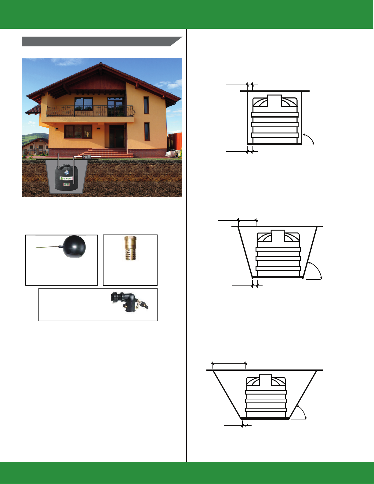
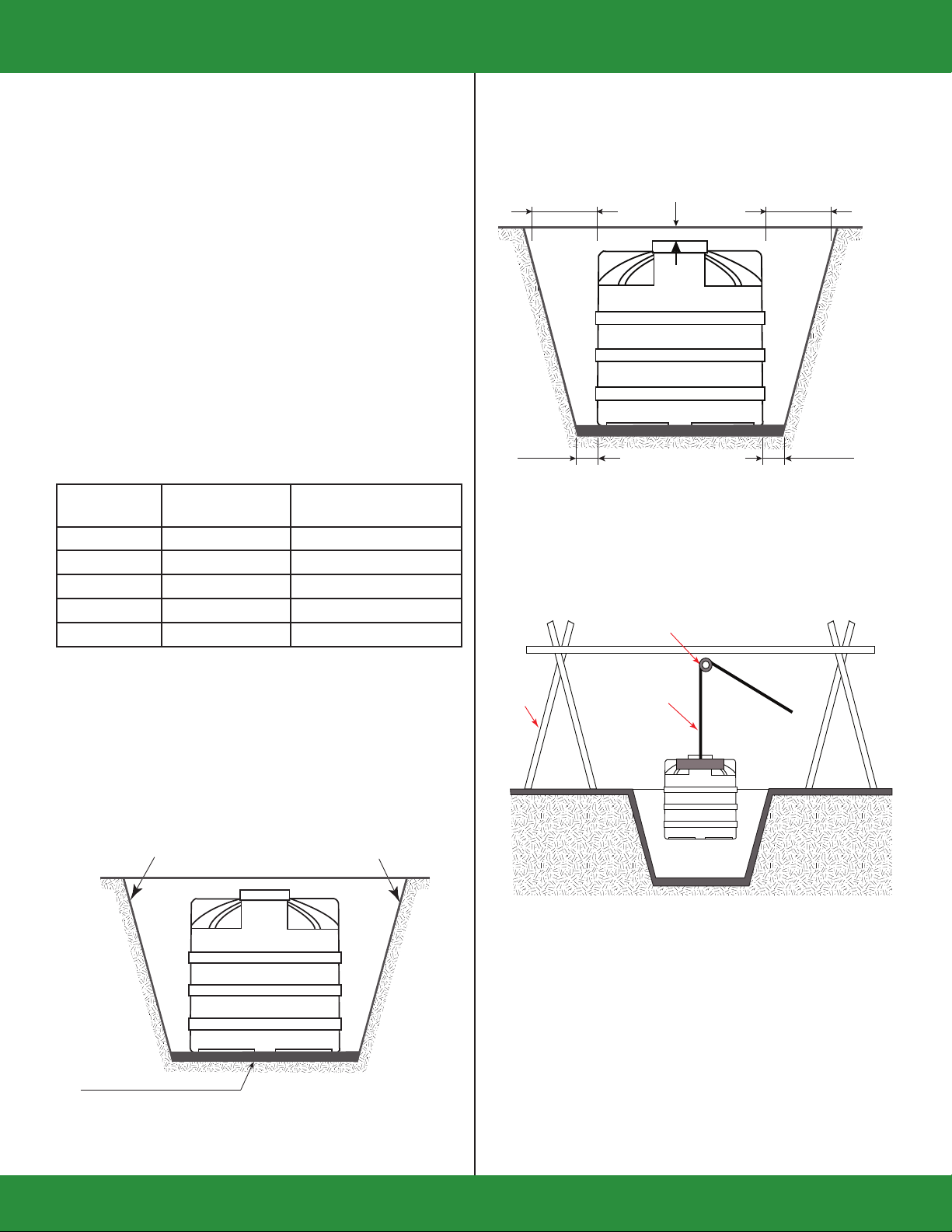
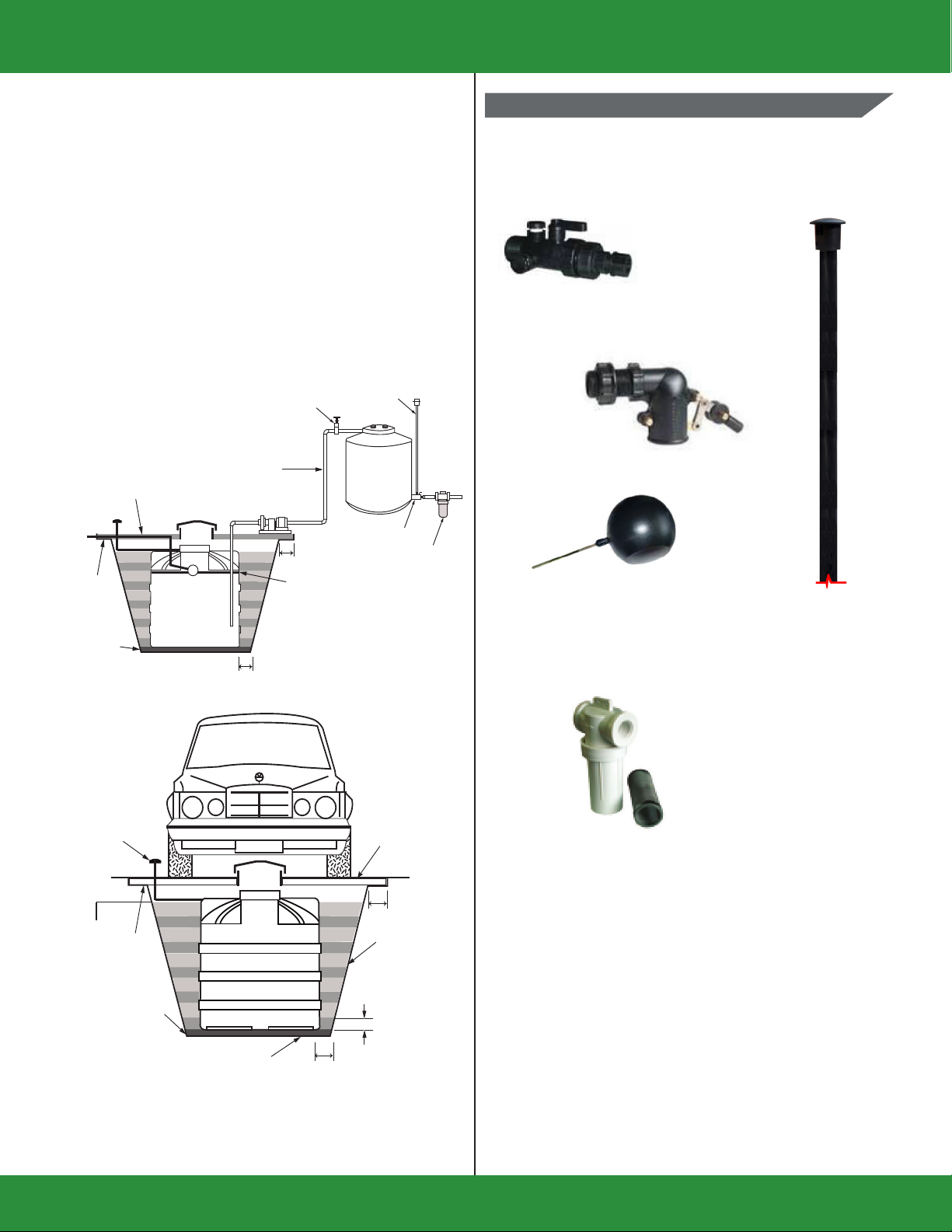
General installation
1. Remove the discharge plug from
the multi-connector, remove all
contents and rinse.
2.
3. Do a nal cleaning of the inside
walls and bottom with a clean, dry
rag or mop.
4.
5. Install the discharge plug on the
manifold and open the valve that
supplies water to your home.
6.
7. Turn on the water supply to your
Cistern, wait for it to ll and it is
ready to use.
5
6
7
8
• Cisterns should be washed before installation.
• The tank should always be cleaned every six months. Check
the lter and connections and make necessary adjustments
and repairs.
• The Cistern should always be covered.
• When using a pumping system, the inlet pipe should be
anchored to cushion any movement on the Cistern connector.
• The system should be installed in an easily accessible location
to allow for inspection and to facilitate proper maintenance.
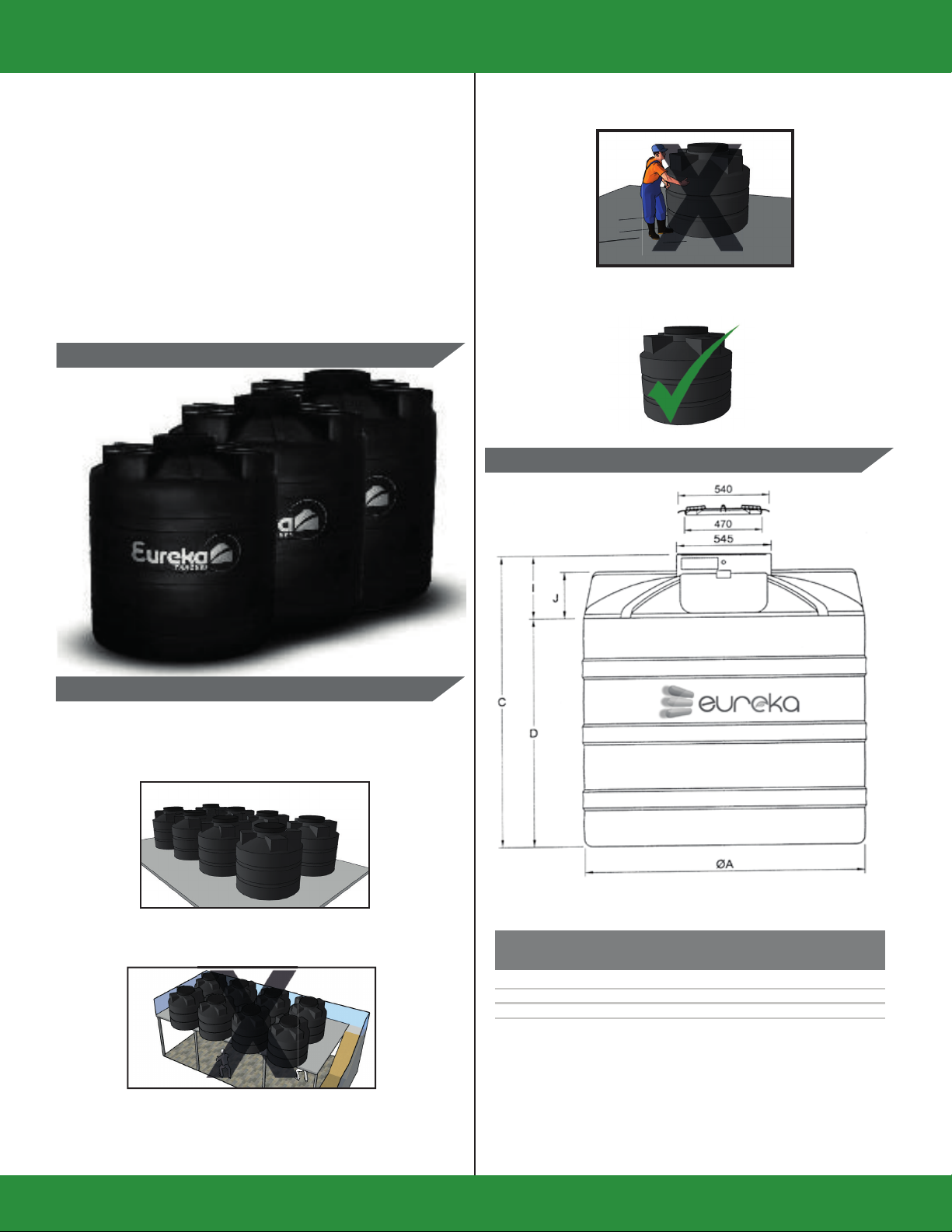
• When storing the Cistern before installation, be sure to keep it
in an upright position on a smooth, level surface.
• The temperature of the liquid to be stored must not exceed 60°
Celsius.
• For the installation of additional accessories to the Cistern, it is
important to consult your authorized supplier beforehand.
• Cistern tanks are not re resistant. Do not store them near a
ame or heat exceeding 80° Celsius.
• Make sure the level of the support surface of the tank.
• Make sure that the support surface is larger than the bottom
of the tank.
• Do not place the tank on irregular ground.
• Do not place the tank on separate parts or beams.
• Do not place the tank on irregular surfaces, vegetation, roots
or elements that may damage the bottom of the tank.
1. Shut o the water supply to the
Cistern.
2. Empty your cistern until there
is about 5 cm of water at the
bottom.
3. Shut o the water supply to your
house by closing the valve.
4. Wash the inside walls and the
bottom of your Cistern with
a plastic bristle brush and
disinfectant liquid soap.
1
2
3
4
Maintenance
5.
6.
7.
8.

Para mayor información contáctenos a los teléfonos:
www.plycem.com contactoply[email protected]
Find us in:
PLYCEM Construsistemas El Salvador S.A.
PLYCEM Construsistemas Costa Rica S.A.
INTE/ISO 14001:2015
SGA-008/01/2010
SISTEMA DE GESTIÓN
AMBIENTAL
CERTIFICADO
001-CP-2001
PRODUCTO
CERTIFICADO
069-CP-2013
PRODUCTO
CERTIFICADO
INTE/ISO 45001:2018
SST-009/2020
SISTEMA DE GESTIÓN DE
LA SEGURIDAD Y SALUD
EN EL TRABAJO
CERTIFICADO
INTE/ISO 45001:2018
SST-006/2020
SISTEMA DE GESTIÓN DE
LA SEGURIDAD Y SALUD
EN EL TRABAJO
CERTIFICADO
Manufactured by:
Table of contents
Other Elementia Materials Water Heater manuals
Popular Water Heater manuals by other brands

AEG
AEG MTH 350 Operating and installation instructions

STIEBEL ELTRON
STIEBEL ELTRON SN 5 SL Operating and installation instructions

Rinnai
Rinnai RUC80i, RUC98i RU80e, RU98e Installation and operation manual

Kärcher
Kärcher HG 43 manual

Maytag
Maytag Series Six user guide

PVI
PVI QuickDraw PV500-24 Installation and maintenance manual