RBI FUTERA III Series User manual

FUTERA III SERIES FINNED COPPER
GAS BOILERS (MODEL MB)
& WATER HEATERS (MODEL MW)
INSTALLATION & OPERATION MANUAL
INSTALLER, THESE INSTRUCTIONS TO BE AFFIXED ADJACENT TO THE BOILER / WATER HEATER.
CONSUMER, RETAIN THESE INSTRUCTIONS FOR FUTURE REFERENCE PURPOSES.
DESIGNED AND TESTED ACCORDING TO A.S.M.E. BOILER AND PRESSURE
VESSEL CODE, SECTION IV FOR A MAXIMUM ALLOWABLE WORKING PRESSURE
OF 160 PSI,
1103 kPa
WATER.
FTIII-IOM-1
260 North Elm Street 1300 Midway Boulevard
Westfield, MA 01085 䡲Mississauga, Ontario L5T 2G8 Canada
Phone: (413) 568-9571 Phone: (905) 670-5888
Fax: (413) 568-9613 Fax: (905) 670-5782
www.rbiwaterheaters.com
WARNING: If the information in this manual is not followed exactly, a fire
or explosion may result causing property damage, personal injury or loss of life.
Do not store or use gasoline or other flammable vapors and liquids in the vicinity of
this or any other appliance.
WHAT TO DO IF YOU SMELL GAS:
• Do not try to light any appliance.
• Do not touch any electrical switch. Do not use any phone in your building.
• Immediately call your gas supplier from a neighbor’s phone. Follow the gas
supplier’s instructions.
• If you cannot reach your gas supplier, call the fire department.
Installation and service must be performed by a qualified installer, service agency or
the gas supplier.
WARNING: Failure to properly vent this unit can cause excessive amounts of carbon
monoxide resulting in severe personnal injury or death!

2
FUTERA III INSTALLATION AND OPERATION INSTRUCTIONS
CONTENTS
Before Your Start page 2
Ratings & Capacities page 3
Boiler/Water Heater Location page 3
Combustion Air & Ventilation page 3
General Venting Guidelines page 5
Common Vent Systems page 11
General Piping Requirements page 12
Heating System Piping page 13
Domestic Water Supply Piping page 17
Gas Supply Piping page 21
Electrical Wiring page 22
General Operation page 22
Operating Instructions page 23
Checking & Adjustments page 25
Control Description page 26
MPA Staging Control page 26
Diagnostics page 27
Maintenance page 28
Trouble-Shooting page 30
Repair Parts page 31
Startup Sheet page 37
BEFORE YOU START
This manual covers the application, installation, operation
and maintenance of a Futera III Series finned copper
heating boiler/water heater.
To obtain the safe, dependable, efficient operation and long
life for which this heating boiler/water heater was designed,
these instructions must be read, understood and followed.
AVERTISSMENT. Assurez-vous de bien suivre les instructions données dans cette notice pour
réduire au minimum le risque d’incendie ou d’explosion ou pour éviter tout dommoge matériel,
toute blessure ou la mort
Ne pas entreposer ni utiliser d’essence ou ni d’autres vapeurs ou liquides inflammables à
proximité de cet appareil ou de tout autre appareil.
QUE FAIRE SI VOUS SENTEZ UNE ODEUR DE GAZ:
• Ne pas tenter d’allumer d’appareil.
• Ne touchez à aucun interrupteur; ne pas vous servir des téléphones se trouvant dans le
bâtiment.
• Appelez immédiatement votre fournisseur de gas depuis un voisin. Suivez les intructions du
fournisseur.
• Si vous ne purvez rejoindre le fournisseur, appelez le service des incendies.
L’installation et l’entretien doivent être assurés par un installateur ou un service d’entretien
qualifié ou par le fournisseur de gaz.
The Futera III Series finned copper heating boiler/water
heaters have been design certified by CSA for use with
natural and propane gas under the latest revision of ANSI-
Z21.10.3/CSA 4.3, Gas Water Heaters, ANSI-Z21.13/CSA
4.9, Gas-Fired Low Pressure Steam and Hot Water Boilers
and CAN1-3.1, Industrial and Commercial Gas Fired
Packaged Boilers. Each unit has been constructed and
hydrostatically tested for a maximum working pressure of
160 psi,
1103 kPa
in accordance with Section IV of the
A.S.M.E. Boiler and Pressure Vessel Code.
All aspects of the boiler/water heater installation must
conform to the requirements of the authority having juris-
diction, or, in the absence of such requirements, to the
National Fuel Gas Code, ANSI Z223.1/NFPA 54-latest
revision. Where required by the authority having jurisdiction,
the installation must conform to the Standard for Controls
and Safety Devices for Automatically Fired Boilers, ANSI/
ASME CSD-1.
In Canada, the installation must be in accordance with the
requirements of CSA B149.1 or .2, Installation Code for
Gas Burning Appliances and Equipment.
If installed in the Commonwealth of Massachusetts, you
MUST FOLLOW the additional instructions contained in
RBI’s instruction sheet MA IOM. If you don’t have a copy
call your RBI representative.
The owner should maintain a record of all service work
performed with the date and a description of the work done.
Include the name of the service organization for future
reference.
Direct all questions to your RBI distributor or contact the
RBI Customer Service Department at: 260 North Elm
Street, Westfield, MA 01085 for US or 1300 Midway
Boulevard, Mississauga ONT L5T 2G8 for Canada. Always
include the model and serial numbers from the rating plate
of the boiler/water heater in question.

3
FUTERA III INSTALLATION AND OPERATION INSTRUCTIONS
RATINGS & CAPACITIES
Before undertaking the installation of the Futera III Series
boiler/water heater check the rating plate to ensure that the
unit has been sized properly for the job. The “Net I=B=R
Ratings” specify the equivalent amount of direct cast iron
radiation that the unit can supply under normal conditions.
Also ensure that the unit has been set up for the type of
gas available at the installation site. Other important
considerations are the availability of an adequate electrical
supply, fresh air for combustion and a suitable chimney or
vent system.
BOILER/WATER HEATER LOCATION
1. This boiler/water heater is suitable for indoor
installations. Locate the boiler/water heater in an area
that provides good access to the unit. Servicing may
require the removal of jacket panels. Allow the
minimum clearances between adjacent construction
and the boiler/water heater as listed in Table 1.
NOTE: Service clearances are not mandatory, but are
recommended to ensure ease of service should it be
required.
Table 1
Clearance to Service
Combustibles Clearance
in
mm
in
mm
Top 6
153
30
762
Back 6
153
24
610
Left Side 6
153
12
306
Right Side 6
153
12
306
Front 6
153
30
762
2. An optimum site will be level, central to the piping
system, close to a chimney or outside wall and have
adequate fresh air for combustion. Ensure that the
boiler/water heater is level from front to back and from
side to side. Use metal shims to level the boiler/water
heater. Electrical and electronic components must also
be protected from exposure to water during operation
and maintenance. DO NOT install this boiler/water
heater in a location that would subject any of the gas
ignition components to direct contact with water or
excessive moisture during operation or servicing.
3. Ensure that the floor is structurally sound and will
support the weight of the boiler/water heater.
NOTE: The Futera III may be installed directly on
combustible flooring, but never on carpeting.
4. Locate the boiler/water heater in an area that will
prevent water damage to adjacent construction should
a leak occur or during routine maintenance. If such
a location doesn’t exist, a suitable drain pan that’s
adequately drained must be installed under the unit.
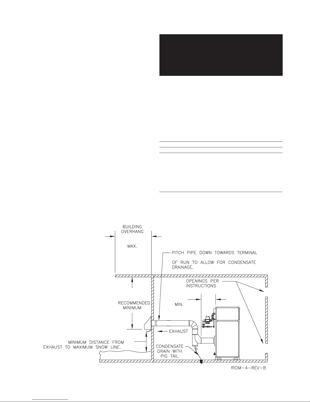
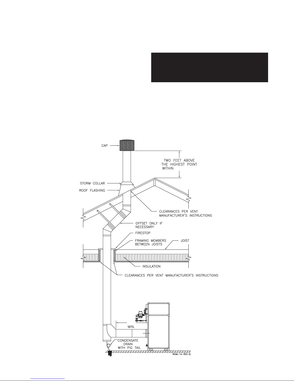
5. DO NOT place this boiler/water heater in a location that
would restrict the introduction of combustion air into
the unit or subject it to a negative pressure, see
“GENERAL VENTING GUIDELINES”.
6. NEVER place this boiler/water heater in a location that
would subject it to temperatures at or near freezing,
see the “FREEZE PROTECTION” section on page 12.
WARNING: Never store combustible materials,
gasoline or any product containing flammable
vapors or liquids in the vicinity of the boiler/water
heater. Failure to comply with this warning can
result in an explosion or fire causing extensive
property damage, severe personal injury or death!
COMBUSTION AIR & VENTILATION
WARNING: This boiler/water heater must be
supplied with combustion air in accordance with
Section 5.3, Air for Combustion & Ventilation, of the
latest revision of the National Fuel Gas Code, ANSI
Z223.1/NFPA 54 and all applicable local building
codes. Canadian installations must comply with
CAN/ CGA B149.1 or .2 Installation Code for Gas
Burning Appliances and Equipment, or applicable
provisions of the local building codes. Failure to
provide adequate combustion air for this boiler/
water heater can result in excessive levels of
carbon monoxide which can result in severe
personal injury or death!
To operate properly and safely this boiler/water heater
requires a continuous supply of air for combustion. NEVER
store objects on or around the boiler/water heater!
CAUTION: Combustion air contaminated with
fluorocarbons or other halogenated compounds such
as cleaning solvents and refrigerants will result in the
formation of acids in the combustion chamber. These
acids will cause premature failure of the boiler/water
heater voiding the warranty!
CAUTION: If the boiler/water heater is operated while
the building is under construction it MUST be
protected from wood, concrete, sheet rock and other
types of dust. Failure to properly protect the unit from
construction dust will damage the unit voiding the
warranty!
Buildings will require the installation of a fresh air duct or
other means of providing make-up air if the intake air option
isn’t used. Any building utilizing other gas burning
appliances, a fireplace, wood stove or any type of exhaust
fan must be checked for adequate combustion air when all
of these devices are in operation at one time. Sizing of an
outside air duct must be done to meet the requirements
of all such devices.
WARNING: Never operate the Futera III in an
environment subjected to a negative pressure
unless it is Direct Vented. Failure to comply with
this warning can result in excessive levels of
carbon monoxide causing severe personal injury
or death!

4
FUTERA III INSTALLATION AND OPERATION INSTRUCTIONS
All Air From Inside The Building
If the Futera III is to be located in a confined space,
the minimum clearances listed in Table 1 must be
maintained between it and any combustible construction.
When installed in a confined space without the intake
air option, Figures 5, 6 and 7, two permanent openings
communicating with an additional room(s) are required.
The combined volume of these spaces must have
sufficient volume to meet the criteria for an unconfined
space. The total air requirements of all gas utilization
equipment, fireplaces, wood stoves or any type of
exhaust fan must be considered when making this
determination. Each opening must have a minimum free
area of 1 in2/1000 Btu/hr,
2200 mm
2
/kW
based on the
total input rating of ALL gas utilization equipment in the
confined area. Each opening must be no less than
100 in2,
64,516 mm
2
in size. The upper opening must
be within 12 in,
305 mm
of, but not less than 3 in,
76 mm
from, the top of the enclosure. The bottom
opening must be within 12 in,
305 mm
of, but not less
than 3 in,
76 mm
from, the bottom of the enclosure.
All Air From Outside The Building
When installed in a confined space without utilizing the
intake air option two permanent openings communicating
directly with, or by ducts to, the outdoors or spaces that
freely communicate with the outdoors must be present.The
upper opening must be within 12 in,
305 mm
of, but not
less than 3 in,
76 mm
from, the top of the enclosure. The
bottom opening must be within 12 in,
305 mm
of, but not
less than 3 in,
76 mm
from, the bottom of the enclosure.
Where directly communicating with the outdoors
or communicating with the outdoors through vertical
ducts, each opening shall have a minimum free area of
1 in2/4000 Btu/hr,
550 mm
2
/kW
of the total input rating
of all of the equipment in the enclosure.
Where communicating with the outdoors through horizontal
ducts, each opening shall have a minimum free area of
1 in2/2000 Btu/hr,
1100 mm
2
/kW
of the total input rating
of all of the equipment in the enclosure.
When ducts are used, they must have the same cross-
sectional area as the free area of the opening to which they
connect.
When calculating the free area necessary to meet the
make-up air requirements of the enclosure, consideration
must be given to the blockage effects of louvers, grills and
screens. Screens must have a minimum mesh size of
1/4 in,
6.4 mm
. If the free area through a louver or grill is
not known, ducts should be sized per Table 2.
Table 2 – Make-up Air Louver Sizing
Required Cross Sectional Area
Input 1/4 in
6.4 mm
75% Free Area 25% Free Area
(MBH) Wire Screen
Metal Louvers Wooden Louvers
in2
cm
2
in2
cm
2
in2
cm
2
500 125
806
167
1077
500
3226
750 187
1206
250
1613
750
4839
1000 250
1613
333
2148
1000
6452
1250 313
2019
416
2684
1250
8065
1500 375
2419
500
3226
1500
9677
1750 437
2819
583
3761
1750
11,290
1999 500
3226
667
4303
2000
12,900
Canadian installations must comply with CSA B149.1 when
air supply
is provided by natural air flow from the outdoors
for
natural draft
, partial fan-assisted, fan-assisted, or
power draft-assisted
burners
, there shall be a permanent
air supply
opening(s) having a cross-sectional area of not
less than 1 in2per 7,000 Btuh
(310 mm
2
per kW)
up to
and including 1 million Btuh, plus 1 in2per 14,000 Btuh
(155 mm
2
per kW)
in excess of 1 million Btuh.
Intake Air Option – General Guidelines
This configuration provides combustion air directly to the
boiler/water heater’s air intake using a dedicated pipe when
using the direct vent option. The RBI air intake adapter
must be fitted to the blower inlet. Combustion air can be
drawn in horizontally through the same outside wall which
terminates the exhaust gases or vertically through the roof,
see Figures 1, 2, 3 & 4.
WARNING: Common intake air systems may be
used provided the common duct is sized properly
and an intake combustion air damper is installed
in the intake air pipe of each heater. Improper
installation can result in excessive levels of carbon
monoxide which can cause severe personal injury
or death!
Single wall galvanized smoke pipe, single wall aluminum
pipe, flexible aluminum pipe, PVC or CPVC pipe can be
used for the intake air pipe. It must be sized per Table 3.
Table 3 - Intake Air Pipe Sizing
Model For Vertical For Horizontal
Size (Up to 60') (Up To 60')
in
mm
in
mm
500 8
203
6
152
750 8
203
6
152
1000 8
203
6
152
1250 10
254
8
203
1500 10
254
10
254
1750 12
305
12
305
2000 12
305
12
305
All joints in metal intake air systems must be secured using
corrosion resistant fasteners and sealed using a suitable
Silicone caulk. If PVC or CPVC is used, the joints must be
cleaned with a suitable solvent and connected using a
solvent based PVC cement. The combustion air system
MUST be supported by the building structure not the
boiler/water heater.

5
FUTERA III INSTALLATION AND OPERATION INSTRUCTIONS
VENT SYSTEM OPTIONS
The Futera III may be vented the following ways:
1) Direct Vent, Positive Pressure, Category IV uses a
vent system certified to UL 1738 for installations in the
United States, ULS636 for installations in Canada.
Combustion air is piped from the outdoors to the
blower inlet.
2) Side Wall Vent, Positive Pressure, Category IV uses
a vent system certified to UL 1738 for installations in
the United States, ULS636 for installations in Canada.
Combustion air is obtained from the space in which
the unit is installed.
3)
Vertical/ChimneyVent, Negative Pressure, Category II
uses an approved metal chimney system.
NOTE: All venting, combustion air material supplied by
installer.
CAUTION: A combustion air damper interlocked with
the unit should be installed in the intake air pipe when
the infiltration of subfreezing air could occur, otherwise
the unit could freeze up voiding the warranty!
Intake Air Option – Vertical Guidelines
The maximum equivalent length for the vertical intake
air pipe is 60 ft,
18.3 m
. Each 90˚ elbow and the intake
air terminal are equal to 10 linear ft,
3.0 m
of pipe, see
Table 3.
An approved, nonrestrictive intake air terminal must be
used. The intake air terminal must terminate as shown in
Figure 3. The penetration point in the roof must be properly
flashed and sealed.
Intake Air Option – Horizontal Guidelines
The maximum equivalent length for the horizontal intake
air pipe is 60 ft,
18.3 m
. Each 90˚ elbow and the intake air
terminal are equal to 10 linear ft,
3.0 m
of pipe. If horizontal
runs exceed 5 ft
1.5 m
they must be supported at 3 ft,
0.9 m
intervals with overhead hangers. The certified intake
air terminal from RBI must be used, see Figures 1, 2
and 4.
GENERAL VENTING GUIDELINES
WARNING: The vent installation must be in
accordance with Part 7, Venting of Equipment, of
the National Fuel Gas Code, ANSI Z223.1/NFPA 54-
latest revision or applicable provisions of the local
building codes. Canadian installations must
comply with CAN/CGA B149.1 or .2 Installation
Code. Improper venting can result in excessive
levels of carbon monoxide which can result in
severe personal injury or death!
All vent systems must be fully supported by the building
structure and not by the boiler/water heater. Appropriate
thimbles and fire-stops must be used where required.
WARNING: Common vent systems must be
properly engineered and sized to provide a
negative draft of 0.1 in,
2.5 mm
W.C. at the flue
outlet. Common positive pressure vent systems
are not to be used. Improper installation can result
in excessive levels of carbon monoxide which can
cause severe personal injury or death!

6
FUTERA III INSTALLATION AND OPERATION INSTRUCTIONS
DIRECT VENT,
POSITIVE PRESSURE, CATEGORY IV
In this configuration the boiler/water heater blower is used
to push the flue products to the outdoors while drawing
combustion air from the outdoors. The Intake Air
Option instructions under the “COMBUSTION AIR &
VENTILATION” section must be followed! The vent system
must be sized per Table 4.
Table 4 – Category IV
Model Pipe Diameter
Size (Up to 60')
in
mm
500 5
127
750 5
127
1000 6
152
1250 6
152
1500 8
203
1750 10
254
2000 10
254
Horizontal Direct Vent Systems – Figures 1 & 2
The vent materials used in horizontal vent systems must
be certified to UL 1738 for installations in the United States,
ULS636 for installations in Canada. The certified vent
terminal from RBI must also be used.
The maximum equivalent length for the horizontal vent pipe
is 60 ft,
18.3 m
.Each 90˚ elbow and the vent terminal are
equal to 10 linear ft,
3.0 m
of pipe. If any part of a single
wall metal vent system passes through an unheated space,
it must be insulated with insulation rated for 400°F,
204
°
C
.
Structrual penetrations must be made using approved fire-
stops. For best results, horizontal vent systems should be
as short and straight as possible.
The vent system must be both gas tight and watertight. All
seams and joints in metal pipes must be joined and sealed
in accordance with the vent system manufacturer’s
instructions.
When horizontal vent runs exceed 5 ft,
1.5 m
they must be
supported at 3 ft,
0.9 m
intervals with overhead hangers.
The vent system must be pitched down, toward the vent
terminal, 1/4 in/ft,
20 mm/m.
If any part of a single wall metal
vent system passes through an unheated space it must be
insulated with insulation rated for 400˚F,
204
°
C
.
Horizontal vent systems shall terminate at least 4 ft,
1.2 m
below, 4 ft,
1.2 m
horizontally from or 1 ft,
0.30 m
above any door, window or gravity air inlet into
any building. It must not terminate less than
4 ft
,
1.2 m
horizontally from, and in no case above or below, unless
a 4 ft,
1.2 m
horizontal distance is maintained, from electric
meters, gas meters, regulators and relief equipment and
not less than 7 ft,
2.1 m
from any adjacent public walkway.
The bottom of the vent terminal(s) shall be located at
least 5 ft,
1.5 m
above the air intake terminal(s) unless
there is a minimum 5 ft,
1.5 m
horizontal separation
between them. Avoid terminal locations likely to be affected
by winds, snowdrifts, people and pets. Protect building
materials and vegetation from degradation caused by the
flue gases.
Vertical Direct Vent Systems – Figure 3
If any part of a single wall metal vent system passes
through an unheated space, it must be insulated with
insulation rated for 400˚F,
204
°
C
. Structural penetrations
must be made using approved fire-stops.
An approved, nonrestrictive vent terminal must be used.
The top of a vertical vent system must extend at least
51/2ft,
1.7 m
above the roof surface and maximum snow
line that it passes through, 4 ft,
1.2 m
above the intake air
terminal, see Figure 3.
In addition the vent system must conform to the dimensions
shown in Figure 3. The penetration point in the roof must
be properly flashed and sealed.
The vent system must be gas tight. All seams and joints
in metal pipes must be joined and sealed in accordance
with the vent system manufacturer’s instructions.
Combination Direct Vent Systems – Figure 4
The boiler/water heater can be vented vertically with the
intake air piped horizontally through an outside wall. Follow
the instructions in the Intake Air Option – Horizontal
Guidelines on page 5. Also follow the general instructions
in the “COMBUSTION AIR & VENTILATION” and
“GENERAL VENTING GUIDELINES” sections.

7
FUTERA III INSTALLATION AND OPERATION INSTRUCTIONS
Figure 1– Horizontal Air Intake and Venting for a Single Direct Vent System
Figure 2 – Horizontal Air Intake and Venting for Multiple Direct Vent Systems
When running horizontal combustion air and venting for single or multiple units, exhaust and combustion air terminals
must be installed on the same plane (outside wall) in order to prevent pressure differences due to prevailing winds. In
cold climates, double-wall or insulated inlet pipe recommended to prevent condensation.
5 FT 1.5 m
3 FT 0.9 m
16 FT 4.9 m
4 FT
1.2 m
5 FT 1.5 m
1/4 IN. PER FOOT
20 mm/m
1.5 FT 0.5 m
5 FT 1.5 m
1.5 FT 0.5 m
2 IN. 5.0 cm
4001 & LARGER
2001 TO 4000
1001 TO 2000
500 TO 1000
MBH FT m
15 4.6
20 6.1
51.5
10 3.1
kW
146 TO 293
293 TO 586
586 TO 1172
1172 & LARGER

8
FUTERA III INSTALLATION AND OPERATION INSTRUCTIONS
Figure 3 - Vertical Air Intake and Venting for Direct Vent System
Figure 4 – Combination Direct Vent Systems
10 FT 3.1 m
4 FT
1.2 m
5 FT
1.5 m
1.5 FT
0.5 m
5 1/2 FT
1.7 m
1.5 FT. .5 m
10 FT. 3.1 m
3 FT. 1 m

9
FUTERA III INSTALLATION AND OPERATION INSTRUCTIONS
WARNING: If an appliance using any type of a
mechanical draft system operating under positive
pressure is connected to a chimney flue, never
connect any other appliances to this flue. Doing
so can result in excessive levels of carbon
monoxide which can cause severe personal injury
or death!
Chimney Inspection & Sizing
A thorough inspection of the masonry chimney must be
performed to ensure that the chimney is clean, properly
constructed, lined and sized. Exterior masonry chimneys
should not be used unless properly lined to prevent
condensation and draft problems. Table 5 lists the
equivalent breeching and flue sizes required for the boiler/
water heater.
Table 5 - Equivalent Breeching & Chimney Size,
Negative Pressure
Model Size Pipe Diameter
in
mm
500 6
152
750 6
152
1000 7
178
1250 8
203
1500 8
203
1750 10
254
2000 10
254
Note: These sizes are based on a 20 ft,
6.1m
chimney height.
Figure 5 – Side Wall Venting
SIDE WALL VENT,
POSITIVE PRESSURE, CATEGORY IV
In this configuration the boiler/water heater blower is used
to push the flue products horizontally to the outdoors, see
Figure 5. The air for combustion is taken from the space
in which the unit is installed. The applicable instructions
under the “COMBUSTION AIR & VENTILATION” section
must be followed! The vent guidelines under the Horizontal
Direct Vent Systems section must also be followed.
VERTICAL/CHIMNEY VENT,
NEGATIVE PRESSURE, CATEGORY II
The Futera III is listed as a Category II appliance when
vented vertically into a listed metal chimney system,
Figures 6 & 7. The chimney must provide a negative
pressure not greater than 0.15 in,
3.8 mm
W.C. at the
boiler/water heater flue collar with the unit running. A
barometric damper must be installed between the flue
collar and the vent connector when negative pressures
exceed 0.15 in,
3.8 mm
W.C.
NOTE: When using a listed metal chimney system the
chimney system manufacturer’s instructions must be
followed.
When more than one appliance is connected to the same
chimney flue, the flue must be large enough to safely vent
the combined output of all of the appliances.
1.5 FT 0.5 m
1/4 IN. PER F00T 20 mm/m
4 FT
1.2 m
3 FT
0.9 m
24"
0.6 m

10
FUTERA III INSTALLATION AND OPERATION INSTRUCTIONS
Figure 6 – Vertical Venting with a Metal Chimney System
Vent Connections
Locate the boiler/water heater as close to the chimney as
possible. Use the shortest, straightest vent connector
possible for the installation. If horizontal runs exceed 5 ft,
1.5 m
they must be supported at 3 ft,
0.9 m
intervals with
overhead hangers. Use a single wall stainless steel vent
pipe the same diameter as the flue collar to connect the
boiler/water heater to a masonry chimney. When using a
listed metal chimney system use the appropriate vent
connector.
The vent connector should be sloped up toward the
chimney at a minimum rate of 1/4 in/ft,
21 mm/m
. On
masonry chimneys the connector must terminate flush with
the inside of the chimney flue, Figure 7. Fasten each single
wall vent connection with at least 3 corrosion resistant
sheet metal screws.
Always provide a minimum clearance of 6 in,
152 mm
between single wall vent pipe and any combustible
materials.
WARNING: Failure to maintain minimum
clearances between vent connectors and any
combustible material can result in a fire causing
extensive property damage, severe personal injury
or death!
10 FT. 3.1 m
24"
.6 m

11
FUTERA III INSTALLATION AND OPERATION INSTRUCTIONS
Figure 7 – Vertical Venting using a Lined Masonry Chimney
Inspecter de façon visuelle le système d’évacu-ation
pour déterminer la grosser et l’inclinaison horizontale
qui conviennent et s’assurer que le système est exempt
d’obstruction, d’étranglement de fruite, de corrosion et
autres défaillances qui pourraient présenter des risques.
c) Insofar as is practical, close all building doors and
windows and all doors between the space in which the
appliances remaining connected to the common venting
system are located and other spaces of the building.Turn
on clothes dryers and any appliance not connected to the
common venting system.Turn on any exhaust fans, such
as range hoods and bathroom exhaust, so they will operate
at maximum speed. Do not operate a summer exhaust
fan for a boiler installation. Close fireplace dampers.
Dans la mesure du possible, fermer toutes les portes
et les fenêtres du bâtiment et toutes les portes entre
l’espace où les appareils toujours raccordés du système
d’évacuation sont installés et les autres espaces du
bâtiment. Mettre en marche les sécheuses, tous les
appareils non raccordés au système d’évacuation
commun et tous les ventilateurs d’extraction comme les
hottes de cuisinère et les ventilateurs des salles de bain.
S’assurer que ces ventilateurs fonctionnent à la vitesse
maximale. Ne pas faire fonctionner les ventilateurs
d’été. Fermer les registres des cheminées.
COMMON VENT SYSTEMS
If an existing boiler/water heater is removed from a
common venting system, the common venting system may
then be too large for the proper venting of the remaining
appliances connected to it. At the time of removal of an
existing boiler/water heater, the following steps shall be
followed with each appliance remaining connected to the
common venting system placed in operation, while the
other appliances remaining connected to the common
venting system are not in operation.
Au moment du retrait d’une chaudière existante, les
mesures suivantes doivent être prises pour chaque
appareil toujours raccordé au système d’évacuation
commun et qui fonctionne alors que d’autres appareils
toujours raccordés au système d’évacuation ne fonction-
nent pas: système d’évacuation
a) Seal any unused openings in the common venting system.
Sceller toutes les ouvertures non utilisées du sys-
tème d’évacuation.
b) Visually inspect the venting system for proper size and
horizontal pitch and determine there is no blockage or
restriction, leakage, corrosion and other deficiencies
which could cause an unsafe condition.
24"
.6 m

12
FUTERA III INSTALLATION AND OPERATION INSTRUCTIONS
d) Place in operation the appliance being inspected. Follow
the lighting instructions. Adjust thermostat so appliance
will operate continuously.
Mettre l’appareil inspecté en marche. Suivre les
instructions d’allumage. Régler le thermostat de façon
que l’appareil fonctionne de façon continue.
e) Test for spillage at the draft hood relief opening after 5
minutes of main burner operation. Use the flame of a
match or candle, or smoke from a cigarette, cigar or
pipe.
Faire fonctionner le brûleur principal pendant 5 min
ensuite, déterminer si le coupe-tirage déborde à
l’ouverture de décharge. Utiliser la flamme d’une
allunette ou d’une chandelle ou la fumée d’une
cigarette, d’un cigare ou d’une pipe.
f) After it has been determined that each appliance
remaining connected to the common venting system
properly vents when tested as outlined above, return
doors, windows, exhaust fans, fireplace dampers and
any other gas-burning appliance to their previous
condition of use.
Une fois qu’il a été d éterminé, selon la métode
indiquée ci-dessus, que chaque appareil raccordé au
système d’évacuation est mis à l’air libre de façor
adéquate. Remettre les portes et les fenêtres, les
ventilateurs, les registres de cheminées et les appareils
au gaz à leur position originale.
g) Any improper operation of the common venting system
should be corrected so the installation conforms with
the National Fuel Gas Code, ANSI Z223.1/NFPA 54.
When resizing any portion of the common venting
system, the common venting system should be resized
to approach the minimum size as determined using the
appropriate tables in Appendix F in the National Fuel
Gas Code, ANSI Z223.1/ NFPA 54 and or CAN/CGA
B149 Installation Codes.
Tout mauvais fonctionnement du systéme d’évacu-tion
commun devrait étré corrigé de façor que l’installation
soit conforme au National Fue Gas Code, ANSI
Z223.1/NFPA 54 et (ou) aux codes d’installation CAN/
CGA-B149. Si la grosseur d’une section du système
d’ évacuation doit étré modifiée, le système devrait étré
modifié pour respecter les valeurs minimales des
tableaux pertinents de l’appendice F du National Fuel
Gas Code, ANSI Z223.1/ NFPA 54 et (ou) des codes
d’installation CAN/CGA-B149.
GENERAL PIPING REQUIREMENTS
CAUTION: Improper piping of this boiler/water heater
will void the manufacturer’s warranty and can cause
boiler failure resulting in flooding and extensive
property damage! Excessive water hardness causing
scaling in the copper heat exchanger tubes is NOT
covered under the manufacturer’s warranty, see Table
7. Excessive pitting and erosion of the internal surface
of the copper heat exchanger tubes is NOT covered
under the manufacturer’s warranty if the result of high
water flow rates, see Table 7. Return water
temperatures below 125˚F,
52
°
C
will result in heat
exchanger damage from excessive condensation
voiding the manufacturer’s warranty, see Primary /
Secondary Piping, Figure 9.
NOTE: Shut off valves and unions should be installed
at the inlet and outlet connections of the boiler/hot
water heater to provide for isolation of the unit should
servicing be necessary.
Freeze Protection
Installations in areas where the danger of freezing exists
are not recommended unless proper freeze protection is
provided. The following precautions MUST be observed:
1. A continuous flow of water through the unit MUST be
maintained! The pump responsible for flow through the
boiler/water heater must run continuously!
2. An ethylene glycol/water mixture suitable for the
minimum temperature that the unit will be exposed to
must be used. The pump must be capable of producing
a minimum of 15% more flow and overcoming a 20%
increase in head loss. Domestic water systems must be
isolated from the water heater by the use of a heat
exchanger or other approved method.
3. If the unit must be shut off for any reason the electric,
gas and water supplies MUST be shut off and the unit
and its pump completely drained.
Relief Valve
Pipe the discharge of the pressure relief valve as shown
in Figure 8.
WARNING: Never install any type of valve between
the boiler/water heater and the relief valve or an
explosion causing extensive property damage,
severe personal injury or death may occur!
Flow Switch
The flow switch supplied with the boiler/water heater must
be wired to the terminal strip in the control panel to prevent
the boiler from firing unless there’s adequate water flow
through the unit. The flow switch must be installed in the
supply piping adjacent to the boiler outlet connection.
CAUTION: Failure to properly install the flow switch
may result in damage to the boiler/water heater heat
exchanger voiding the warranty!

13
FUTERA III INSTALLATION AND OPERATION INSTRUCTIONS
HEATING SYSTEM PIPING
General Piping Requirements
All heating system piping must be installed by a qualified
technician in accordance with the latest revision of the
ANSI/ASME Boiler and Pressure Vessel Code, Section IV,
and ANSI/ASME CSD-1, Standard for Controls and Safety
Devices for Automatically Fired Boilers. All applicable local
codes and ordinances must also be followed. A minimum
clearance of 1 in,
25 mm
must be maintained between
heating system pipes and all combustible construction. All
heating system piping must be supported by suitable
hangers not the boiler. The thermal expansion of the
system must be considered when supporting the system.
A minimum system pressure of 12 psig,
82.7 kPa
must
be maintained.
Heating Boiler Piping Connections
The supply and return connections should be sized to suit
the system, see Table 6.
Table 6 – Supply & Return Pipe Sizing
Model Size Supply Size Return Size
500 thru 1000 2" NPT 2" NPT
1250 thru 2000 2 1/2" NPT 2 1/2" NPT
Pump Requirements
This low mass boiler requires a continuous minimum water
flow for proper operation. The system pump must be sized
to overcome the head loss of the boiler and the heating
system in order to achieve the required temperature rise.
Table 7 provides the heat exchanger pressure drop and
temperature rise figures. The temperature rise across the
boiler must never exceed 35˚F,
19.4˚C
. The adjustable
pump delay turns the pump on each time the burner fires
and runs the pump for 20 to 600 seconds after the call for
heat is satisfied.
CAUTION: A temperature rise outside of the range
listed in Table 7 indicates that the flow rate through the
heat exchanger is incorrect which will damage the heat
exchanger voiding the warranty! The maximum
allowable temperature rise is 35°F,
19.4
°
C
.
The maximum allowable flow rate through a Futera III
boiler is 97 GPM,
6.1 L/s
on 500 through 1000 models
and 136 GPM,
8.6 L/s
for 1250 through 2000 models.
The Cupro-Nickel heat exchanger allows for 108 GPM,
6.8 L/s
on 500 through 1000 models and 151 GPM,
9.5 L/s
on 1250 through 2000 models.
Figure 8 – Futera III Piping

14
FUTERA III INSTALLATION AND OPERATION INSTRUCTIONS
Table 7 - Temperature Rise Table
∆T = 20°F∆
T = 11.1
°
C
Model Flow Rate Pres. Drop
Flow Rate Pres. Drop
Number GPM Ft
L/s kPa
500 42.5 0.53
2.7 1.5
750 63.8 1.57
4.0 4.6
1000 85.0 3.44
5.4 10.1
1250 106.3 2.11
6.7 6.2
1500 127.5 3.57
8.0 10.5
∆T = 25°F∆
T = 13.9
°
C
Model Flow Rate Pres. Drop
Flow Rate Pres. Drop
Number GPM Ft
L/s kPa
500 34.0 0.35
2.1 1.0
750 51.0 1.04
3.2 3.1
1000 68.0 2.27
4.3 6.7
1250 85.0 1.40
5.4 4.1
1500 102.0 2.36
6.4 7.0
1750 119.0 3.67
7.5 10.8
2000 136.0 5.39
8.6 15.9
∆T = 30°F∆
T = 16.7
°
C
Model Flow Rate Pres. Drop
Flow Rate Pres. Drop
Number GPM Ft
L/s kPa
750 42.5 0.74
2.7 2.2
1000 56.7 1.62
3.6 4.8
1250 70.8 1.00
4.5 2.9
1500 85.0 1.68
5.4 5.0
1750 99.2 2.62
6.3 7.7
2000 113.3 3.84
7.2 11.3
∆T = 35°F∆
T = 19.4
°
C
Model Flow Rate Pres. Drop
Flow Rate Pres. Drop
Number GPM Ft
L/s kPa
750 36.4 0.56
2.3 1.6
1000 48.6 1.22
3.1 3.6
1250 60.7 0.75
3.8 2.2
1500 72.9 1.27
4.6 3.7
1750 85.0 1.97
5.4 5.8
2000 97.1 2.89
6.1 8.5
Low Water Cutoff
If a boiler is installed above any radiation elements it must
be fitted with a low water cutoff device.
Refer to the wiring diagram supplied with the boiler/water
heater for proper wiring connections.
Expansion Tank & Air Separator
An expansion tank or other means to control thermal
expansion must be installed in the heating system. An
expansion tank must be installed close to the boiler on the
suction side of the pump. An air scoop and automatic air
vent must also be installed to eliminate air trapped in the
system.
Primary/Secondary Piping
Boilers connected to heating systems using zone valves,
zone pumps, or systems that have excessive flow rates or
return water temperatures less than 125˚F,
52˚C
must be
isolated from these systems to protect the boiler.
Variable Water Flows
Figure 9 shows a typical primary/secondary piping system.
A dedicated pump is used to maintain a constant water flow
through the boiler. This secondary pump is sized to
overcome the head loss of the boiler and secondary piping
system while supplying the flow rate required to maintain
the desired temperature rise across the boiler. The primary
pump is sized to provide the required flow to the heating
system. The secondary piping connections to the primary
system piping must not be more than 12 in,
305 mm
apart
to ensure zero pressure drop in the primary system, see
Figure 9.
Low Return Water Temperatures
To prevent the problems associated with condensation of
the products of combustion due to low return water
temperatures a primary/secondary piping system with a
bypass and bypass valve must be installed, see Figure 10.
The bypass and bypass valve must be sized the same
as the secondary piping. A balancing valve must also be
installed in the supply side of the secondary piping
downstream of the bypass. The balancing valve should
be adjusted to divert some of the heated discharge water
into the return water until the required inlet water
temperature is achieved. The primary and secondary
pumps should be sized to provide the required flow through
each system. The secondary piping connections to
the primary system piping must not be more than 12 in,
305 mm
apart to ensure zero pressure drop in the primary
system, see Figure 10.
Multiple Boiler Systems
Systems using multiple boilers can also be installed using
a primary/secondary manifold system, Figure 11.
Piping For Use With Cooling Units
The boiler, when used in connection with a refrigeration
system, must be installed so the chilled medium is piped
in parallel with the boiler. Appropriate valves must be used
to prevent the chilled water from entering the boiler.
When a boiler is connected to a heating coil that may be
exposed to refrigerated air from an air handling device, the
piping system must be equipped with flow-control valves
or some other automatic means of preventing gravity
circulation of the boiler water during the cooling cycle.

15
FUTERA III INSTALLATION AND OPERATION INSTRUCTIONS
1
1
Figure 9 - Typical Primary/Secondary Piping System
(See Notes)
Figure 10 - Low Temperature Piping
(See Notes and Adjustment Procedures)
1. Turn heater on and open valves A & B.
2. After steady-state operation, if T1 is less than Temp-Min
slowly close valve B until T1 climbs to desired operating
temperature above Temp-Min.
3. If T1 is greater than desired operating temperature, slowly
close valve A to adjust to lower desired temperature above
Temp-M in.
4. Check after system operating temperature has
stabilized. Make final adjustments.
5. Follow same adjustment procedure for sealed combustion.
Adjustment Procedure To Maintain Inlet Temperature
Above Dew Point
T1-Temp-Min=110° For Atmospheric
T1-Temp-Min=125° Sealed Combustion
NOTES:
1. Boiler circuit piping must be sized large enough to handle
maximum flow through unit.
2. Boiler pump sized to boiler design flow requirements.
3. All boilers furnished with factory mounted outlet water
temperature gauge.
4. Boiler pump purging required. Use terminals supplied.
Notice: These drawings show suggested piping configuration and valving.
Check with local codes and ordinances for specific requirements.
Operated Valve
Air Vent
Pressure Switch
Aquastat Union
Gas Pressure
Regulator
Automatic
Thermometer
Flow Switch
Pressure
Relief Valve
Reducing Valve
Self-Operated
Check Valve
Pressure
Va lv e
Pump
Motorized Valve
Solenoid
Ball Valve
Bufferfly Valve
Angle Valve
Gate Valve
Globe Valve
Balance Valve
Backflow-
Prevention
Device
H-1 Rev 2
H-3 Rev 2

16
FUTERA III INSTALLATION AND OPERATION INSTRUCTIONS
1
5
Figure 11 - Multiple Boiler Piping (See notes)
Operated Valve
Air Vent
Pressure Switch
Aquastat Union
Gas Pressure
Regulator
Automatic
Thermometer
Flow Switch
Pressure
Relief Valve
Reducing Valve
Self-Operated
Check Valve
Pressure
Va lv e
Pump
Motorized Valve
Solenoid
Ball Valve
Bufferfly Valve
Angle Valve
Gate Valve
Globe Valve
Balance Valve
Backflow-
Prevention
Device
5. Secondary loop pipe diameter must be sized large enough to
handle maximum flow through all units.
NOTES:
1. Boiler circuit piping must be sized large enough to handle
maximum flow through unit.
2. Boiler pump sized to boiler design flow requirements.
3. All boilers furnished with factory mounted outlet water
temperature gauge.
4. Boiler pump purging required. Use terminals supplied.
Notice: These drawings show suggested piping configuration and valving.
Check with local codes and ordinances for specific requirements.
H-15 Rev 2

17
FUTERA III INSTALLATION AND OPERATION INSTRUCTIONS
DOMESTIC WATER SUPPLY PIPING
CAUTION: Proper controls must be used to prevent
water supplied for domestic use from exceeding 130˚F,
54˚C
or a scald injury will occur! When higher water
temperatures are required for appliances such as a
dishwasher, a mixing valve or some other tempering
means must be installed. Households with small
children may require water temperatures less than
120˚F,
49˚C
. Local codes must be complied with!
General Piping Requirements
Ensure that the water heater is equipped with bronze
headers. Piping and components connected to the water
heater must be suitable for use with potable water. The
water heater must not be connected to any heating system
piping or components previously used with a non-potable
water heating appliance. No toxic chemicals, such as those
used for boiler treatment, are to be introduced into the
potable water used for space heating. If a hot water storage
tank is used in the system it must be equipped with a
temperature and pressure relief valve that complies with
ANSI Z21.22 or CAN-4.4 and CAN-4.6.
NOTE: The storage tank must be located as close to
the water heater as possible to prevent excessive head
loss which will reduce flow.
Water Chemistry
The required temperature rise across the water heater is
based on water having a hardness between 8 and 18
grains per gallon with a level of dissolved solids not
exceeding 350 ppm. Water having a hardness less than 8
grains can cause excessive corrosion of the heat
exchanger. Water that has a hardness greater than 18
grains per gallon and/or a level of dissolved solids
exceeding 350 ppm will require a recalculation of the pump
size and temperature rise.
A cupro-nickel heat exchanger may also be required. The
manufacturer should be consulted when these water
conditions are encountered. See Table 8A.
CAUTION:
The maximum allowable flow rate through a
Futera III water heater is 97 GPM,
6.1 L/s
on 500 through
1000 models and 136 GPM,
8.9 L/s
for 1250 through 2000
models. The cupro-nickel heat exchanger allows for
108 GPM,
6.8 L/s
on 500 through 1000 models and
151 GPM,
9.5 L/s
on 1250 through 2000 models, see
Table 8B.
RBI water heaters are designed to run scale free. Due to
the extreme variables of water conditions world wide it is
necessary to consider pH values and water hardness in
relationship to scaling. It is crucial to consider these two
variables when making heat exchanger and pump
selections. If local water conditions are extreme, follow the
guidelines in the Heat Exchanger Selection Table (Table
8A) and the Pumping Performance Table (Table 8B). Scale
free operation can be achieved by using water with a
hardness between 8 and 18 and by maintaining the pH
between 5 and 9. Follow the conditions listed under
NORMAL in the table. In some areas of the country
additional precautions must be observed due to unusual
characteristics of the local water supply. Call the nearest
RBI representative for details.
To properly size the pump a grain hardness and pH test
must be taken at the installation site before the order is
placed. Proper pump sizing will improve heater
performance and help ensure heater longevity.

18
FUTERA III INSTALLATION AND OPERATION INSTRUCTIONS
Table 8A - Futera III Heat Exchanger Selection Graph
Table 8B - Futera III Pumping Performance Requirement
To properly size the pump a grain hardness and pH test must be taken at the installation site before the order is placed.
Proper pump sizing will improve heater performance and help ensure heater longevity.

19
FUTERA III INSTALLATION AND OPERATION INSTRUCTIONS
Expansion Tank
An expansion tank or other means to control thermal
expansion must be installed in the water heating system if
back flow prevention devices are installed.
Pump Requirements
This low-mass water heater requires a continuous mini-
mum water flow for proper operation. The low water flow
switch provided for this unit will shut down the water heater
if flow falls below the required minimum level. Table 8B
provides the heat exchanger pressure drop chart and
temperature rise table. The temperature rise across the
water heater must never exceed 35°F,
19.4
°
C
.
Cold Water Supply
The cold water supply must be piped to the water heater’s
outlet piping between the water heater and the hot water
storage tank. This will prevent untempered water from
entering the water heater, see the Temperature Rise
Control section below. Two typical water heating systems
are shown in Figures 12 & 13.
Temperature Rise Control
Water returned to the water heater inlet must not be less
than 125˚F,
52˚C
or excessive condensation of the products
of combustion will damage the water heater voiding the
warranty. The method outlined below can be employed to
prevent this condition from occurring.
A balancing valve should be installed on the outlet side of
the water heater for purposes of adjusting the flow rate
through the heat exchanger. Thermometers are installed
on both the inlet and outlet of the water heater for
determining the temperature rise through the unit.
The proper velocity through the water heater must be
maintained in accordance with Table 8B for efficient
operation and long life. If the temperature rise through the
water heater is lower than recommended the water velocity
is too high. Premature erosion of the heat exchanger will
occur. Conversely, if the temperature rise is higher than
recommended in Table 8B the flow rate is too low. Scaling
and softening of the heat exchanger will occur.
Thermostatic Mixing Valve – Water Above 140˚F,
60˚C
Water can be stored at temperatures above 140˚F,
60˚C
provided that a thermostatically controlled mixing valve is
used to temper the hot water to an acceptable temperature
before it’s supplied for domestic use.
The mixing valve MUST be set to prevent a scald injury
from occurring, see the caution against scalding.
Storage of water for domestic use above 140°F,
60
°
C
will
provide an increased quantity of tempered water and help
prevent the growth of water born bacteria.

20
FUTERA III INSTALLATION AND OPERATION INSTRUCTIONS
Figure 13 - Multiple Water Heating Piping (MW Models Only)
(See Notes)
Figure 12 - Typical Water Heating Piping (MW Models Only)
(See Notes)
Operated Valve
Air Vent
Pressure Switch
Aquastat Union
Gas Pressure
Regulator
Automatic
Thermometer
Flow Switch
Pressure
Relief Valve
Reducing Valve
Self-Operated
Check Valve
Pressure
Valve
Pump
Motorized Valve
Solenoid
Ball Valve
Bufferfly Valve
Angle Valve
Valve
Globe Valve
Balance Valve
Temperature &
Pressure
Relief Valve
Vacuum
Relief Valve
Drain Valve
(Typ.)
2
3
1
4
7
8
NOTES:
1. Optional cold water make up and recirculation line location.
2. When using intermittent pump and pump delay, locate remote aquastat well in
lower 1/3 of tank. Install aquastat with heat sensing compound.
3. Thermal expansion tank may be required, check local codes.
4. When using optional factory mounted pump, max pipe length 30' total, 6-90°
elbows, full pipe size.
5. CAUTION: MEASURE WATER HARDNESS AND pH AT JOB SITE.
The pH and water hardness must be measured before selecting heat
exchanger and pump. Consult the Heat Exchanger Graph and
Pumping Performance Table before making selection.
6. Common piping must be sized for maximum combined heater flow.
7. Hot water tanks should be equipped with a combination temperature &
pressure relief valve.
8. MA Code requires an 1/8" hole in check valve to compensate for thermal
expansion.
Notice: These drawings show suggested piping configuration and valving.
Check with local codes and ordinances for specific requirements.
1
2
3
2
7
7
6
68
4
4
D-4 Rev 4
D-1 Rev 4
Other manuals for FUTERA III Series
2
This manual suits for next models
14
Table of contents
Other RBI Water Heater manuals

RBI
RBI DOMINATOR Series User manual

RBI
RBI FUTERA II Series Manual

RBI
RBI FUTERA FUSION Series User manual

RBI
RBI FUTERA III Series User manual

RBI
RBI FUTERA III Series HeatNet User manual

RBI
RBI FB series User manual

RBI
RBI IEW-199 User manual

RBI
RBI 8900 Series User manual

RBI
RBI FUTERA XLF Series User manual

RBI
RBI SB User manual