Elenos ELT50 User manual

Via G. Amendola 9 - 44028 Poggio Renatico (FE) - Italy
Ph. +39 0532 829 965 - Fax +39 0532 829 177
E-Mail: [email protected]
Web Site: www.elenos.com
USER AND TECHNICAL MANUAL
Edizione 1
Rev. 0 - 02/07/2009
Cod. MAN0168
ELT50
ELR50

Page 2 Engineering Department PHONE: +39 0532 829 965 - FAX: +39 0532 829 177
E-Mail: [email protected]
AVVISO IMPORTANTE
Il presente apparato è utilizzabile solo da
titolari di Concessioni Governative
e/o Autorizzazioni Ministeriali
Elenos Srl
WARNING
The use of this device
is subject
to National Regulations.
Elenos Srl
Back to index
Use and maintenance manual

Page 3
Engineering Department PHONE: +39 0532 829 965 - FAX: +39 0532 829 177
E-Mail: [email protected]
Back to index
Use and maintenance manual
REVIEWS

Page 4 Engineering Department PHONE: +39 0532 829 965 - FAX: +39 0532 829 177
E-Mail: [email protected]
Back to index
Use and maintenance manual
First of all thank you for choosing an product.
products are solid state or thermionic tube transmitters that develop power
from a minimum of 20W to a maximum of 30KW.
Great care has been taken during the design of the protection circuitry to ensure compa-
tibility with products from other manufacturers. However the best performance is achieved
when the equipment is used with other products manufactured by .
The unit has been designed to guarantee stable performances over time, without the need
of special maintenance, minimised to a functional fans-check.
Operation of the unit is very easy and intuitive. Even so it is recommended that this manual
and other relevant documentation is read carefully before any operation.
Dear User,
Customer Care

Page 5
Engineering Department PHONE: +39 0532 829 965 - FAX: +39 0532 829 177
E-Mail: [email protected]
Back to index
Use and maintenance manual
INDEX
TECHNICAL CHARACTERISTICS 6
USAGE INSTRUCTION 9
Display Password 11
Display Change of Frequency 13
TECHNICAL SCHEMATICS ELR50 15
TECHNICAL SCHEMATICS ELT50 60

Page 6 Engineering Department PHONE: +39 0532 829 965 - FAX: +39 0532 829 177
E-Mail: [email protected]
Back to index
Use and maintenance manual
1. TECHNICAL CHARACTERISTICS
TECHNICAL CHARACTERISTICS
Page 7
Engineering Department PHONE: +39 0532 829 965 - FAX: +39 0532 829 177
E-Mail: [email protected]
Back to index
Use and maintenance manual
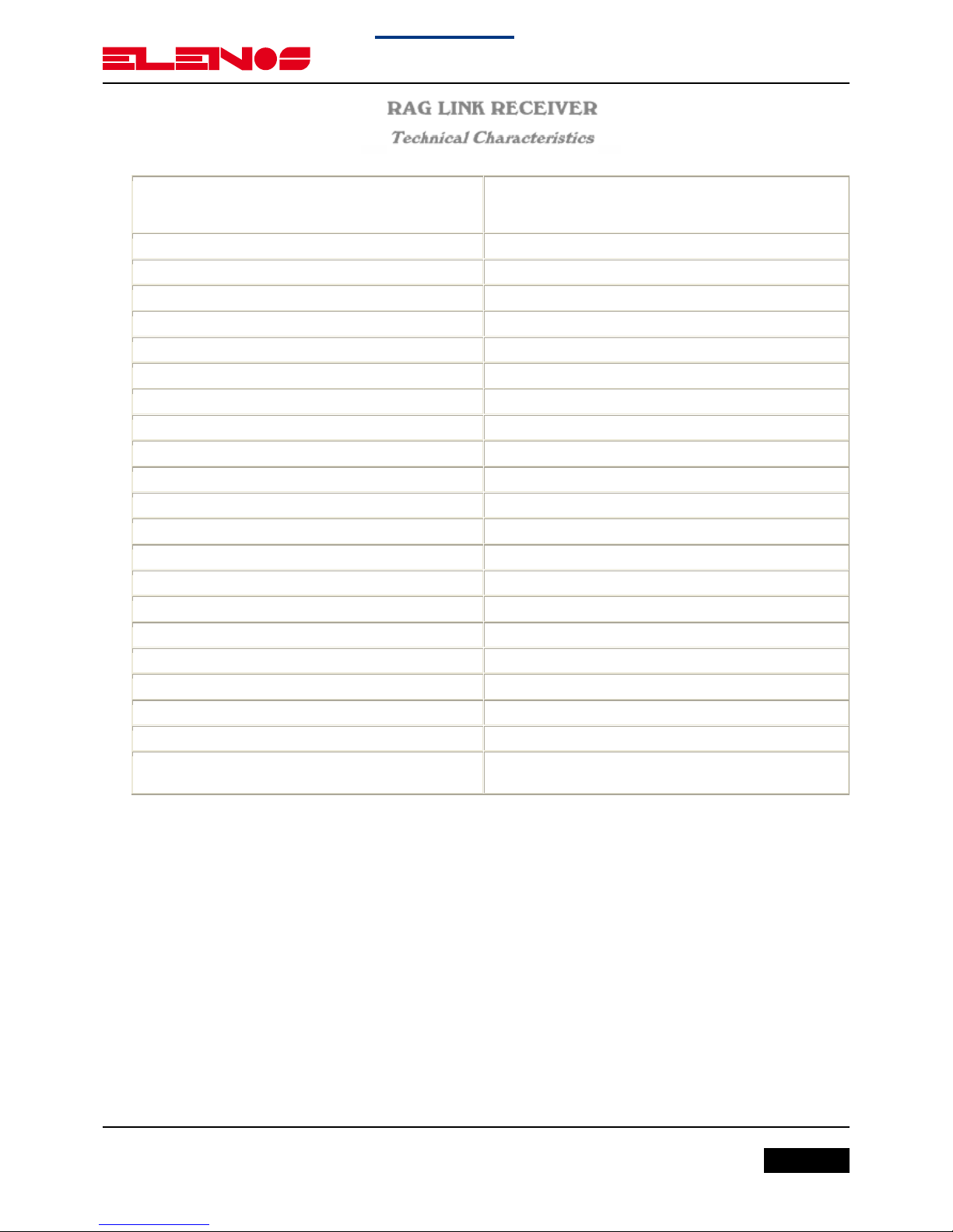
1. TECHNICAL CHARACTERISTICS
Frequency Ranges
200~240 MHz - 300~330 MHz
400~470 MHz - 940 - 960 MHz
(other on request)
Type of Modulation FM Class F3
VCO Tuning 25 MHx
Frequency Stability ± 2.5 ppm (Better on request)
Synthesizer Step 25KHz
Image Rejection 60dB Typ.
RN Noise Figure 6dB or lower
Stereo Separation > 45 dB @ 1 KHx
Distorsion < 0.5% (TYP 0.2 % @ 1KHz)
Base Band 30 Hz - 60 KHz within 0.15 dB
Unweighted S/N Ratio > 72 dB with 0.2 mV input (Typ 78 dB)
Deenphasis 50 or 75 µS
RF Connectors N-F 50 ohm
Base Band-If Connectors BNC-F
Base-Band Impedence 30 ohm
Cooling Forced air
P. Temperature Range 0 ÷ +45°C
Maximum Umidity 90%
AC Supply 100 ÷ 240 Volt; 47 ÷ 63 Hz
DC External Supply (option) 15 Volt Negative Ground
Dimension 3 Units Rack 19" 44 cm Depth
Weight 6.5 Kg

Page 8 Engineering Department PHONE: +39 0532 829 965 - FAX: +39 0532 829 177
E-Mail: [email protected]
Back to index
Use and maintenance manual
1. TECHNICAL CHARACTERISTICS
Frequency Ranges
200~240 MHz - 300~330 MHz
400~470 MHz - 940 - 960 MHz
(other on request)
Type of Modulation FM Class F3
VCO Tuning 25 MHz
Frequency Stability ± 2,5ppm (Bettr 0n request)
Synthesizer Step 25KHz
Power Output 10 Watts
Spurious Emission < -80 dB or better
Harmonic Emission < -65 dB (-80 dB on request)
Stereo Separation > 55 dB @ 1 KHz
Distorsion < 0.2% (TYP 00.8 %) @ 1KHz)
Base Band 30 Hz - 60 KHz within 0.15 dB
Unweighted S/N Ratio > 74 dB rms at 30 Hz ~ 20 KHz
Enphasis 50 or 75 μS - selectable
RF Connectors N-F 50 ohm
Input Base Band Impedence 2 Kohm
Input Mono Impedence 600 Ohm
Cooling Forced air
OP. Temperature Range 0 ÷ +45°C
Maximum Umidity 90%
AC Supply 100 ÷ 240 Volt; 47 ÷ 63 Hz
DC External Supply (option) 12~15 Volt Negative Ground
Dimension 3 Units Rack 19" 44 cm Depth
Weight 7.3 Kg

Page 9
Engineering Department PHONE: +39 0532 829 965 - FAX: +39 0532 829 177
E-Mail: [email protected]
Back to index
Use and maintenance manual
2. USAGE INSTRUCTION
USAGE INSTRUCTION

Page 10 Engineering Department PHONE: +39 0532 829 965 - FAX: +39 0532 829 177
E-Mail: [email protected]
Back to index
Use and maintenance manual
2. USAGE INSTRUCTION
ELENOS
Connected a 50 load or 50 antenna to the RF output, connect the
equipment into a mains supply (100÷240 VAC) with earth point. The
transmitter equipment is factory pre-set to 0.0 W.
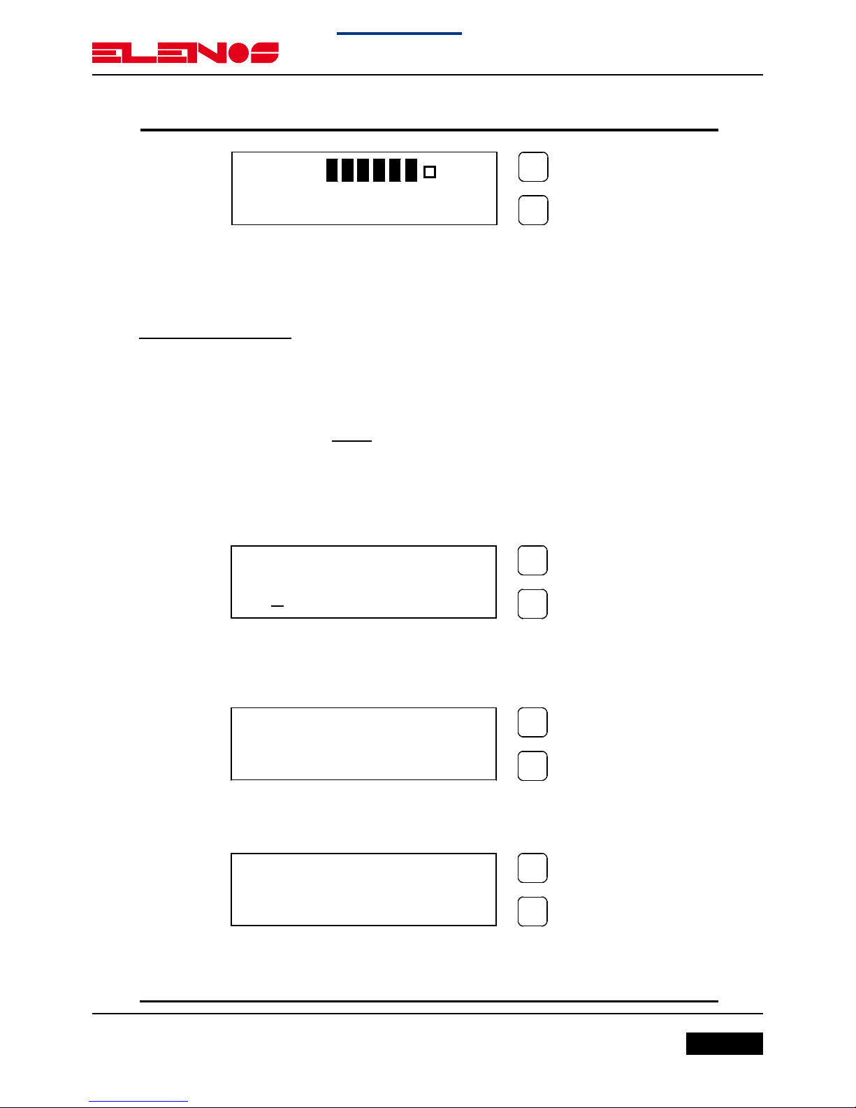
Switch ON the power switch and the yellow V POWER led will light.
The Display will show:
After 3 seconds the green PLL LOCK led will light and the Display will
show an increasing bar, after a further 5 seconds the green ON AIR led
will light and there will be output power.
At this point the Display will show the next parameter for the transmitter:
•Level Modulation (MOD > );
•Forward Power (FRW 5.0W);
•Reflected Power (RFL 0.1W);
instead for the receiver:
•Level Modulation (MOD > );
•Level Signal(50dBuV).
WAIT
WAIT
MOD >
FRW 8.0W RFL 0.0W
Page 11
Engineering Department PHONE: +39 0532 829 965 - FAX: +39 0532 829 177
E-Mail: [email protected]
Back to index
Use and maintenance manual
2. USAGE INSTRUCTION
ELENOS
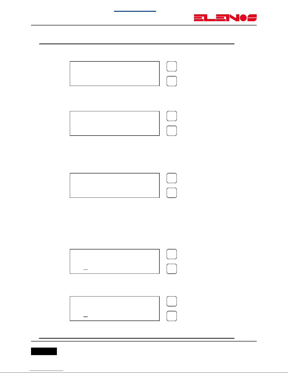
To display the frequency push the SET key.
In order to display the parameter push the SELECT key.
Display Password
The Password mode is factory set to enable, and is not possible change
this SET.
The default password is 1 2 3.
The WAIT of changing the password is as follows:
•Press for 3 seconds the SELECT key;
•Press the SELECT key for move the underscore character position at
the required digit, and press the SET key to confirm the digit.
Carry out the same operation for the two remaining digits.
•If the password is corrected press SET key to confirm, otherwise
press SELECT key to leave the choice.
PASSWORD
01 2 3 4 5 6 7 8 9
PASSWORD
0 1 2 3 4 5 6 7 8 9
*
PASSWORD
0 1 2 3 4 5 6 7 8 9
*
*
*
MOD >
SGN 50dBuV
Page 12 Engineering Department PHONE: +39 0532 829 965 - FAX: +39 0532 829 177
E-Mail: [email protected]
Back to index
Use and maintenance manual
2. USAGE INSTRUCTION
ELENOS
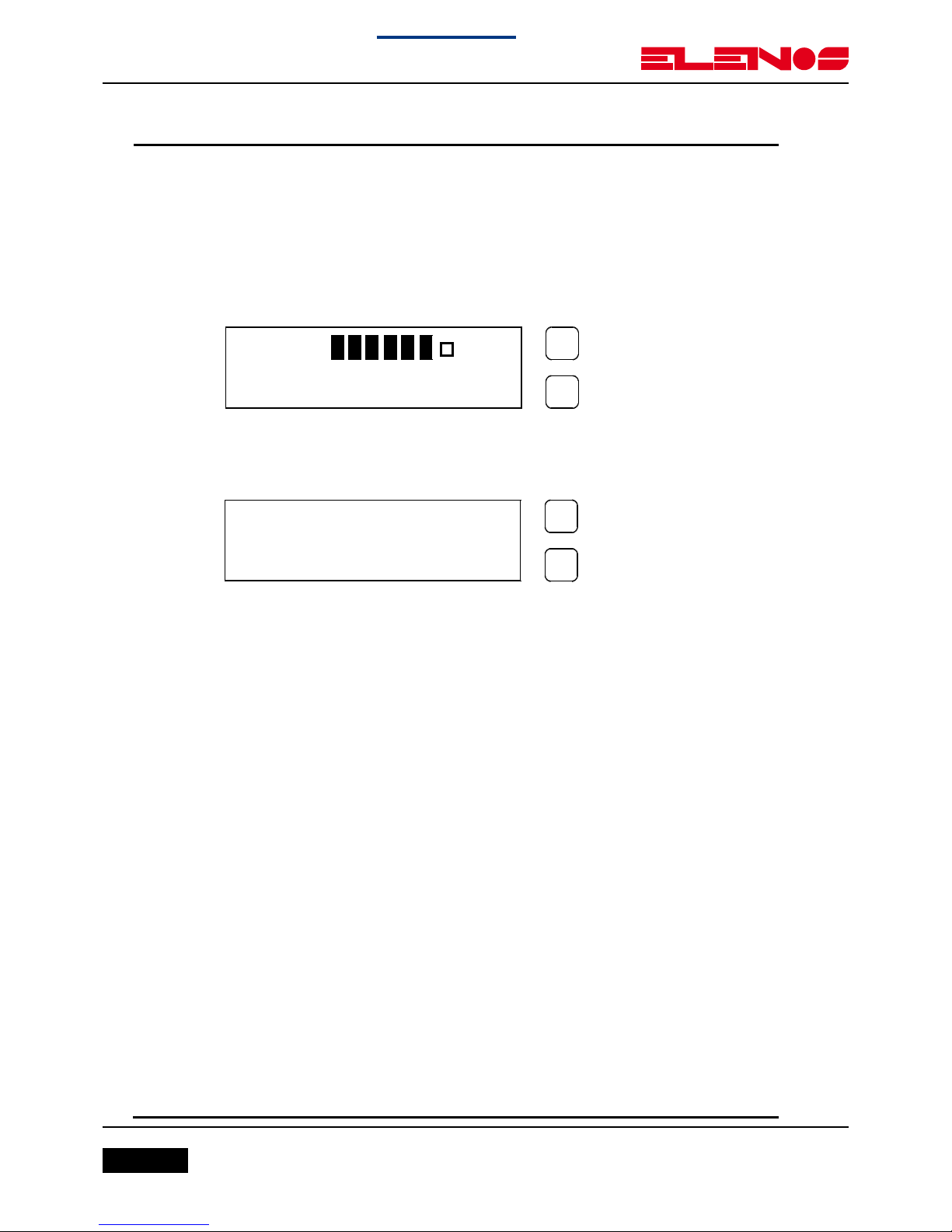
If the password is not corrected an error is displayed:
After few seconds display will show again the parameters.
•When the password is corrected the display will show:
To change the password press the SET key.
To change the frequency press the SELECT key.
•For changing the password proceed at the same method for the
required password:
The confirmation password will be required.
If the password is corrected the display will show:
CONFIRM (Y/N) ?
N=SEL. Y=SET.
NEW PASS . = SEL .
NEW FREQ . = SET .
ERROR
PASSWORD
NEW PASSWORD
01 2 3 4 5 6 7 8 9
CONFIRMATION
01 2 3 4 5 6 7 8 9

Page 13
Engineering Department PHONE: +39 0532 829 965 - FAX: +39 0532 829 177
E-Mail: [email protected]
Back to index
Use and maintenance manual
2. USAGE INSTRUCTION
ELENOS
If the confirmation password is wrong the display will show:
IMPORTANT NOTE
! BE CAREFULLY !
Once the password is set, it must be remembered otherwise neither can
the frequency be changed or a new password entered.
Display Change of Frequency.
•Press 3 seconds the SELECT key and put the correct password, at
this point press again the SELECT key:
•Press the SELECT key to change the digit and press the SET key to
confirm the digit.
The underscore character move the position one place to the left.
STORED
NEW PASSWORD
ERROR
CONFIRMATION
NEW PASS . = SEL .
NEW FREQ . = SET .
FREQUENCY ?
MHz 300.000
Page 14 Engineering Department PHONE: +39 0532 829 965 - FAX: +39 0532 829 177
E-Mail: [email protected]
Back to index
Use and maintenance manual
2. USAGE INSTRUCTION
ELENOS
When the five digit is changed the further press SET key confirm the
new frequency.
At this operation follows the WAIT cycle and after this the display will
show the parameters:
After 7 minutes the display light switch off and the display will show:
MOD >
FRW 8.0W RFL 0.0W
ELENOS
MHz 300.000

Page 15
Engineering Department PHONE: +39 0532 829 965 - FAX: +39 0532 829 177
E-Mail: [email protected]
Back to index
Use and maintenance manual
3. TECHNICAL SCHEMATICS ELR50
TECHNICAL SCHEMATICS ELR50

Page 16 Engineering Department PHONE: +39 0532 829 965 - FAX: +39 0532 829 177
E-Mail: [email protected]
Back to index
Use and maintenance manual
3. TECHNICAL SCHEMATICS ELR50
AUDIO OUTPUT
MPX
MONO
SCA
VCO
PLL
TCXO
12.8
MHz
MICROCONTROLLER
DISPLAY
ELENOS
MHz 300.000
BPF
MIXER
IF DEMODULATOR
RF
INPUT
VAC
VDC
POWER
SUPPLY
MIXER
OL
MHz 59.3
Fo=70 MHz
MHz 10.7
Mod. ELR-50A
1.0
FUNCTIONAL SCHEMATIC
B
1 1Friday, September 14, 2007
Title
Size Document Number Rev
Date: Sheet of
ELENOS
Page 17
Engineering Department PHONE: +39 0532 829 965 - FAX: +39 0532 829 177
E-Mail: [email protected]
Back to index
Use and maintenance manual
3. TECHNICAL SCHEMATICS ELR50
ELENOS
MHz 300.000
Mod. ELR-50A
1.0
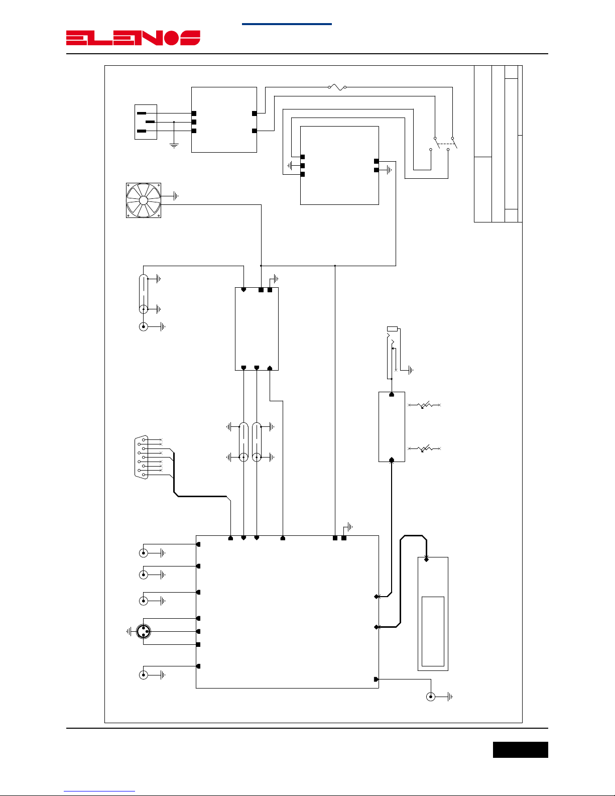
GENERAL SCHEMATIC
B
1 1Wednesday, December 17, 2008
Title
Size Document Number Rev
Date: Sheet of
ELENOS
MICROCONTROLLER
DISPLAY
POWER SUPPLY
+15V
GND
L
GND EARTH
N
EMC FILTER
L IN
GND EARTH
N IN
L OUT
N OUT
Mather Board
+15V
GND
RF PLL
MPX1
SCA1
SCA2
MONO+
MONO-
MONO GND
IF IN
IF TEST
INTERLOCK
RS232
DISPLAY
CONTROL
V-VCO
FRONTAL PANEL
CONTROL AUDIO
RF ACTIVE FILTRER & VCO
RF INPUTIF OUTPUT
+15V
GND
RF PLL
V-VCO
COM
TX
RX
J1
MPX1
J5
SCA1
JR1
MONO
2 1
3 4
J7
RF INPUT
S1 AC MALE
SW1
ON/OFF
1
2
3
4
F1
1A
P1
RS232
5
9
4
8
3
7
2
6
1
J8
IF TEST
COAX2
RG176
COAX1
RG176
MUTE
10K
COAX1
RG303
J4
SCA2
VOLUME
10K
J9
MONITOR
J6
INTERLOCK
FAN1
1
2
Page 18 Engineering Department PHONE: +39 0532 829 965 - FAX: +39 0532 829 177
E-Mail: [email protected]
Back to index
Use and maintenance manual
3. TECHNICAL SCHEMATICS ELR50
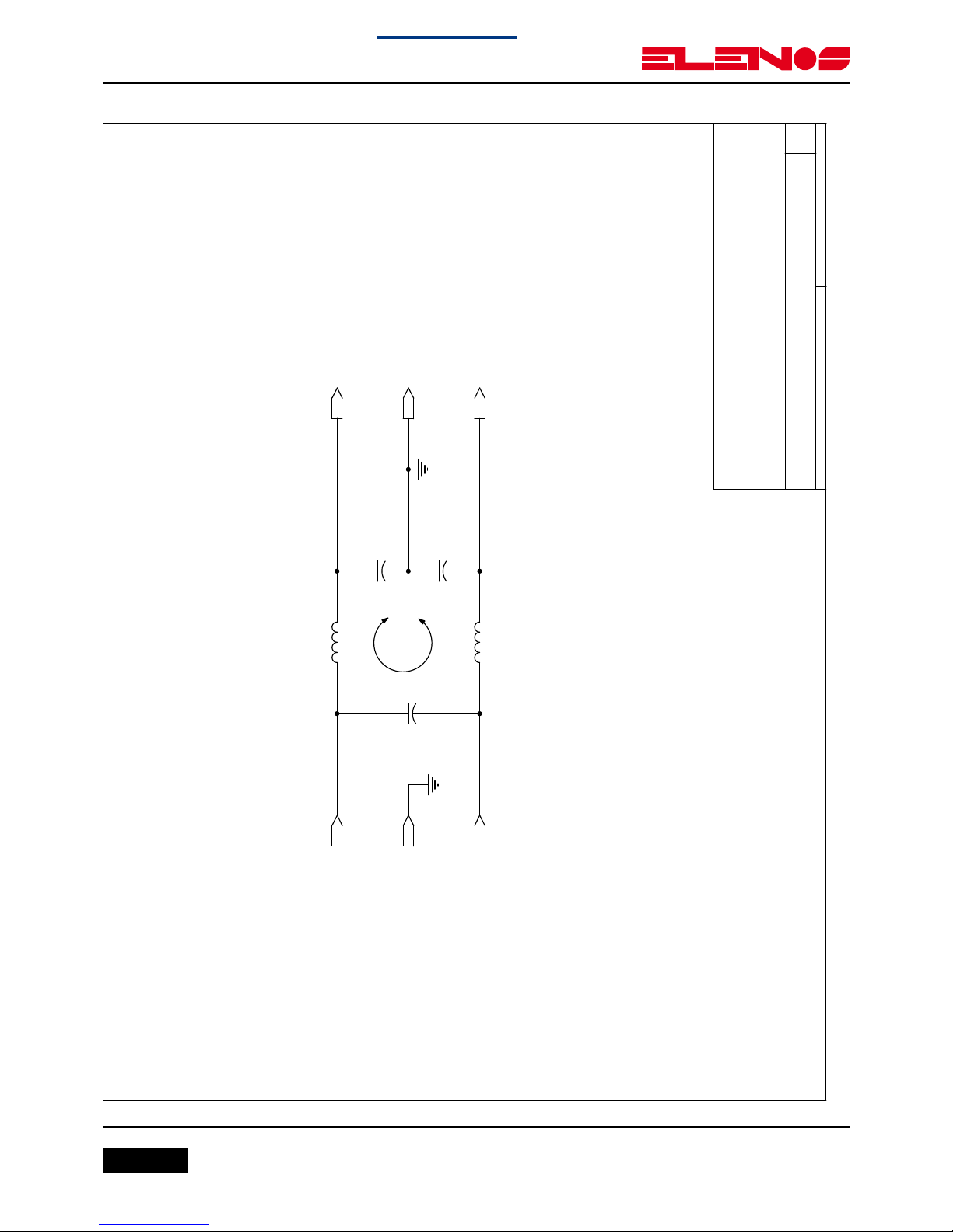
Mod. EMC-02
1.0
EMC FILTER
A
1 1Friday, September 14, 2007
Title
Size Document Number Rev
Date: Sheet of
ELENOS
C2
1uF / 350V
L1
0.8mH
L2
0.8mH
C1
2.2nF / 350V
C3
2.2nF / 350V
L IN
GND EARTH
N IN
L OUT
GND EARTH
N OUT

Page 19
Engineering Department PHONE: +39 0532 829 965 - FAX: +39 0532 829 177
E-Mail: [email protected]
Back to index
Use and maintenance manual
3. TECHNICAL SCHEMATICS ELR50

Page 20 Engineering Department PHONE: +39 0532 829 965 - FAX: +39 0532 829 177
E-Mail: [email protected]
Back to index
Use and maintenance manual
3. TECHNICAL SCHEMATICS ELR50
This manual suits for next models
1
Table of contents


