TTI TCB-550N User manual
4W MOBILE CB TRANSCEIVER
55 N

Microphone Jack
Volume and Power On/Off Knob
LCD Display
Down Button
Up Button
AM/FM and Scan Button
Emergency/Calling & Lock Button
Squelch Control Knob
Antenna Connector
Power 13.2DC
EXT-SPK Jack
CONTENTS
3
3
3
6
1.
2.
3.
4.
5.
6.
7.
8.
9.
10.
11.
12.
13.
14.
15.
9
9
10
11
11
12
13
13
14
15
16
1)
2)
3)
4)
5)
6)
7)
8)
9)
10)
11)
6
6
6
7
7
8
8
8
8
8
9
Introduction
Supplied Accessories
Installation
Transceiver Controls and Functions
LCD Display
Microphone
Menu Setting Mode
How to Operate the Transceiver
Band Selection
Trouble Shooting
CE Declaration
Safety Requirement
Specification
Restrictions on the use
Frequency Table
ENGLISH

ENGLISH
1. Introduction
1 unit
1 unit
1 unit
2 pieces
3 pieces
2 pieces
1 piece
TCB-550N transceiver with Power cable
Microphone with cord
Radio mounting bracket
Radio mounting thumb screw with rubber washer
Mounting screw with washer (for transceiver bracket)
Mounting screw with washer (for microphone bracket)
Microphone mounting brack
2. Supplied Accessories
3. Installation
TCB-550N transceiver is designed to have a good performance in any
conditions that the transceiver operates, using rugged build chassis,
PCB’s and components. This transceiver is also designed for users’
convenience, implementing human ergonomics to locate the knobs
and buttons in the proper places. The combination of well designed
knobs and buttons as well as user friendly graphic layouts will lead
users to quickly adapt themselves for the easy operation. The newly
applied menu mode will make professional users more satisfactory
with pleasure. The elegant and luxury blue LED light supporting the
face design will go well with any vehicles.
This instruction manual has been designed to enable you to get the
best use from your CB Transceiver, therefore you are recommended to
take a few minutes to read this instruction manual before initial use of
your CB Transceiver.
Your transceiver is supplied with a full range of accessories to help you
get started and virtually benefit from all the features straight away.
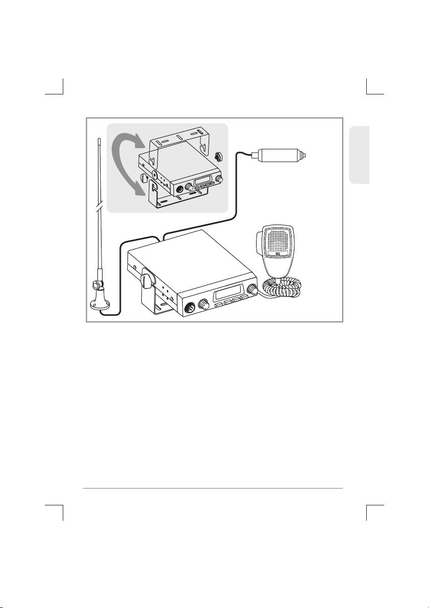
Plan the location of the transceiver and microphone first, which is most
convenient for the operation. The transceiver should normally be
mounted horizontally, but may be mounted vertically. The bracket
supplied can be fitted above or below the case allowing the TCB-550N to
be cradled by the bracket or suspended from it.
3
TCB-550N

Consider that this location of the transceiver should not interfere with
the driver and passengers. Choose a spot where the microphone and
all controls are easily accessible.
1)
2)
3)
Put the mounting bracket on the proper location where you are
going to install.
Drill holes and fix mounting bracket on the location.
Connect the antenna cable plug to the standard receptacle
on the transceiver, which is marked "ANT".
4)
5)
6)
Connect the radio using the included cigarette lighter plug
Mount the microphone bracket on one side of the transceiver, or
near it using two screws included.
Connect the microphone to the transceiver’s microphone
receptacle. Now you are ready to operate the transceiver.
ENGLISH
4TCB-550N
ENGLISH
Installing An Antenna
It is very important to select a good quality high efficiency 27MHz
antenna. A poor quality antenna or one not designed for the
27MHz band will give very poor performance and could cause
damage to the transceiver.
Warning : Never try the operation of your transceiver before
connecting a proper antenna in order not to cause any damage.
Place the antenna as high as possible.
The longer the antenna is, normally the better is the
performance of the transceiver.
Try to mount the antenna in the centre of the surface that you
select.
Make sure that you have a solid metal-to-metal ground
connection.
Be careful not to damage the cable during the installation.
1)
2)
3)
4)
5)
5
TCB-550N
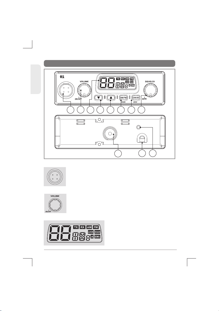
4.Transceiver Controls and Functions
43 5
91110
6 7
2
1
1) Microphone Jack
Insert the microphone into this jack. Use the guide for
easy connection.
ENGLISH
6TCB-550N
8
3) LCD Display
Most of the operational information
is displayed.
Please see item no. 5 for the details
of information.
2) Volume and Power On/Off Knob
To switch on the transceiver turn this knob clockwise.
After clicking sound the transceiver is switched on.The
more you turn this knob clockwise, the bigger the
audio sound grows.
ANTENNA EXT
DC
13.2V
ENGLISH
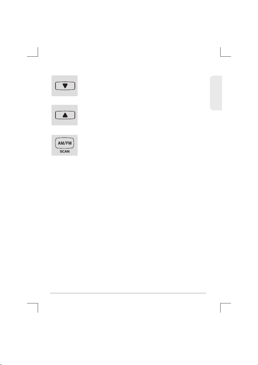
5) Up Button
7
TCB-550N
Press this button briefly to select the channel one by
one that you like to use.
6) AM/FM and Scan Button
AM/FM In many a band mode like EU,I,D and etc. (where
national regulations permit this) this button allows user
to switch between AM and FM modes by momentarily
pressing the button. When the transceiver is used in
UK,UE or EC band mode, this button generates an error
beep.
Scan : Press and hold this button to start scanning upward to catch any
channels that are occupied by others.
To activate/deactivate the channel scan, press and hold the Scan
button. The Scan icon will appear when the channel scan is active.
Scanning will only stop when you deactivate the scan function.
The transceiver will scan through the whole transceiver channels. If
your transceiver detects a valid signal the scan will pause for the period
that has been set by the menu mode setting (continuously receiving or
1-99 seconds for scan receive time and immediate response or 1-99
seconds for scan delay time).
If you press the PTT button when your transceiver detects a signal, the
radio will transmit on the same channel. Scanning will resume after the
scan receive time and/or the scan delay time. Use the up/down buttons
to resume scanning immediately.
If you press the PTT button during scanning, the radio will return to
your original channel. Scanning will resume after the scan receive time
and/or the scan delay time. Use the up/down buttons to resume
scanning immediately.
4) Down Button
Press this button briefly to select the channel one by
one that you like to use.

8) Squelch Control knob
7) Emergency/Calling and Lock Button
Auto Mode : Turn this knob conter-clockwise until you
hear the sound. You transceievr is in the Automatic
squelch mode. This works better in FM mode. than AM
mode. If you are using AM mode, you are recommended
to use the manual squelch mode.
Manual Mode : Turn this knob counter-clockwise until you hear the
background noise(but before click sound to enter the automatic
squelch mode) and then turn the knob a little clockwise until the noise
disappears. In this way, you get the best receive sensitivity.
ENGLISH
8TCB-550N
Emergency/Calling Pressing this button momrntarily
once will lead you to the emergency channel, "CH 9"("CH
19" in some bands) and the EMG icon will be displayed.
Pressing this button twice will lead you to the calling
9) Antenna Connector
10) Power 13.2 DC
Lock : Press this button for more than 2 seconds to activate and
deactivate the keypad lock function. This function locks only the
channel selector, AM/FM & Scan button. Other buttons and selectors
work normal.
channel, "CH 19" ("CH 9" in some bands) will be displayed.
To return to the previous operation mode, momentarily press the
emergency button again.
DC
13.2V
11) EXT-SPK Jack
The power supply cable is connected to this port.
Insert the mail connector of the antenna cable into
this fe-male antenna connector.
Insert the mail connector of the antenna cable into
this fe-male antenna connector.

ENGLISH
5. LCD Display
1
910
8
6
1
2
3
4
5
6
7
8
9
10
Channel Display
Transmit
Receive
AM Mode
FM Mode
Selected Frequency Band
Keypad Lock
Auto Squelch
Scan
EmergencyChannelDisplay
9
TCB-550N
7
6. Microphone
1
2
1
2
PTT Button : While pressing this button,
you can transmit.
4 Pin Microphone Connector : Connect
this to the microphone jack on the front
panel of the transceiver.
2 3 4 5
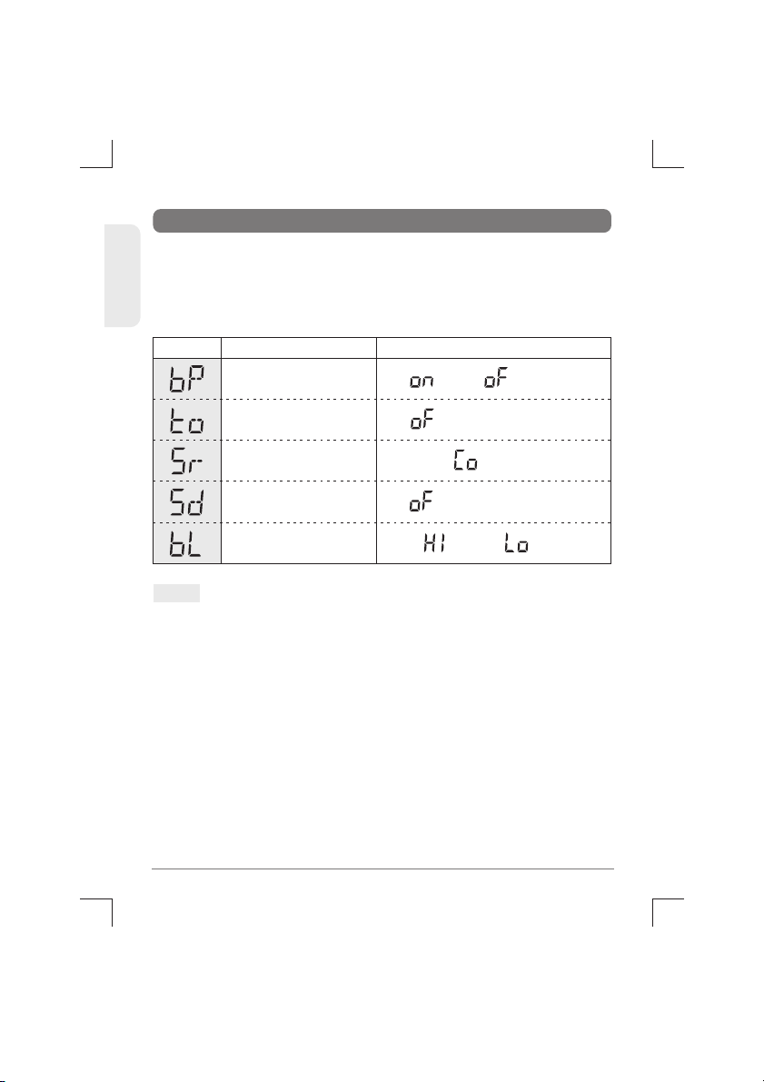
7. Menu Setting Mode
On( ) / Off( )
High( ) / Low( )
Off( ) and 1~99 Sec.
Continue( ) and 1-99 Sec.
Off( ) and 1~99 Sec.
Beep Tone
Backlight Dimmer
Scan Delay Timer
(after Receiving signal)
Scan Receive Timer
Time-out Timer
Display SettingsFunctions
Pressing the Emergency/Calling button, turn on the transceiver. The
transceiver goes to the Menu Setting Mode, which has the following
menu features. This menu setting mode allows you to program user
preferences, activate features and use advanced functions.
10 TCB-550N
ENGLISH
Note :
1.
2.
3.
Use the AM/FM button to selecte the main menu features such as
Beep Tone, Time-out Timer, Scan Receive Timer, Scan Delay Timer
and Backlight Dimmer.
Use the up/down buttons to select or change any value that you
like to have while the values are blinking.
Press the PTT button of the Microphone to complete the selections
and changes and return to the stand-by mode.Or the selections and
changes will be automatically confirmed after 5 seconds of the
selections and changes.
ENGLISH
8. How to Operate the Transceiver
1)
2)
3)
4)
5)
6)
7)
8)
9)
Make sure the microphone is connected to the
microphone jack.
Make sure the power cable is connected properly.
Make sure the antenna is connected to the antenna
receptacle.
It is better to put the squelch control knob turned fully
counter-clockwise.(In case of the manual squelch mode)
Turn on the transceiver and control the volume level.
Adjust the squelch control knob to the optimum level.
Select your desired channel.
To transmit, press the PTT button and speak to the
microphone.
Release the PTT button to receive.
11
TCB-550N
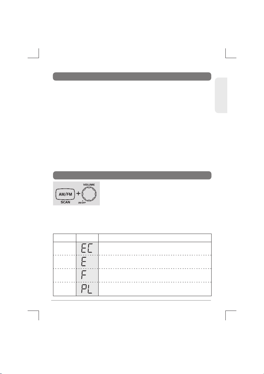
9. Band Selection
Pressing AM/FM button, turn on the transceiver.
The LCD display offers you the band information.
The band chart for each area is as follows.
To change the band,press the Up/Down buttons
while the band information is blinking. Press the PTT button of the
microphone,or wait for 5 seconds to complete the selection and go
to the transmit and receive mode. This transceiver has "EC" band
setting when it is shipped out from the factory.
EC
E
F
PL
DisplaySettings Band
Europe 40 Ch FM 4W
Spain 40 Ch AM/FM 4W
France 40 Ch FM 4W, 40 Ch AM 4W
Poland 40 Ch AM/FM 4W
( Polish frequencies : 5KHz)
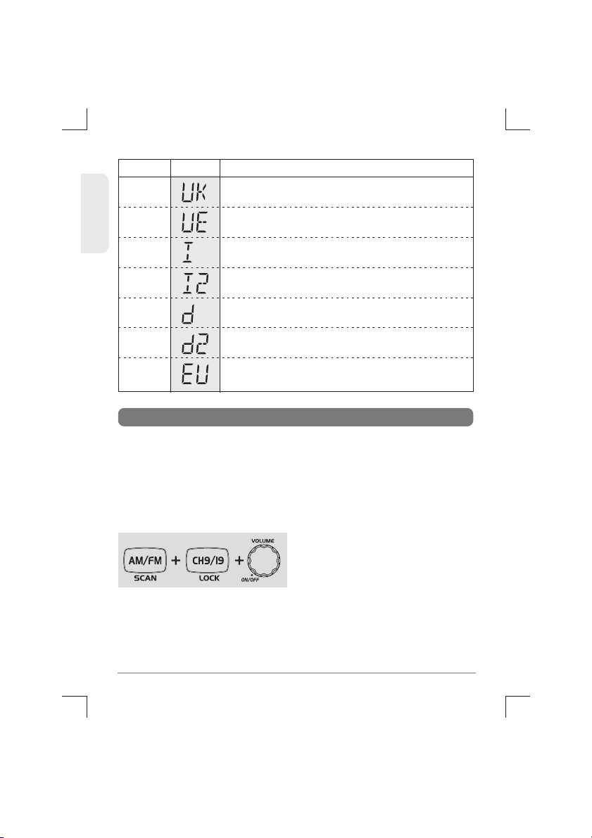
UE
(EU/UK)
I
I2
D
D2
EU
UK
DisplaySettings Band
UK 40 Ch FM 4W (British Frequencies)
Italy 40 Ch AM / FM 4W
Italy 34 Ch AM / FM 4W
Germany 80 Ch FM 4W, 12 Ch AM 4W
Germany 40 Ch FM 4W, 12 Ch AM 4W
Europe 40 Ch FM 4W, 40 Ch AM 4W
UK 40 Ch FM 4W (British Frequencies)
+ CEPT 40 Ch FM 4W (EC)
12 TCB-550N
ENGLISH
10.Trouble Shooting
1)
2)
Switch off the transceiver.
Pressing the AM/FM button
and the CH 9/19 button, switch
on the transceiver.
This will reset the transceiver, so all the memories are erased and
the parameters return to the initial factory setting.
This should fix most problems. In case of further difficulty, please
consult your dealer or visit our website.
If this does not solve the problem, reset your transceiver as follows.
If you experience problems with your TCB-550N transceiver, first
check the power supply source. Poor connection of the power
supply source can cause problems such as no transmission, no
reception or poor reception, and weak or no sound. Ensure that the
microphone and antenna are also well connected.

ENGLISH
CE
versions
of
the
TCB-550N
which
display
the
CE
symbol
on
the
product
label,
Comply
with
the
essential
requirements
of the Radio
Equipment
Directive(
RED)
2014 /53/EU.
13
TCB-550N
12.
Safety Requirement
The same colors are present on the battery and in the fuse box
of the car.
* Red :
Positive pole (+)
* Black : Negative pole (-)
The
power
cable
is
for
13.2V
DC
only.
Be
sure
the
transceiver
is off
before
connecting the leads of the power cable to the power
supply. It is important to observe the polarity even if the unit is
protected against the accidental inversion :
The unit must be wired for the negative ground only.
To avoid damage, do not operate your CB radio without connecting
a proper antenna.
This unit
can
be
used
without license and charges in; Austria,
Belgium, Bulgaria,Cyprus, Czech, Denmark, Estonia, Finland, France,
Germany,
Greece,
Hungary,
Iceland,
Ireland,
Italy,
Latvia,
Lithuania,
Luxembourg,
Malta,
Netherlands,
Norway,
Poland,Portugal,Pomania,
Slovakia,
Slovenia, Spain,
Sweden,
Switzerland, and U.K.
11. CE Declaration

14 TCB-550N
ENGLISH
13. Specification
ENGLISH
15
TCB-550N
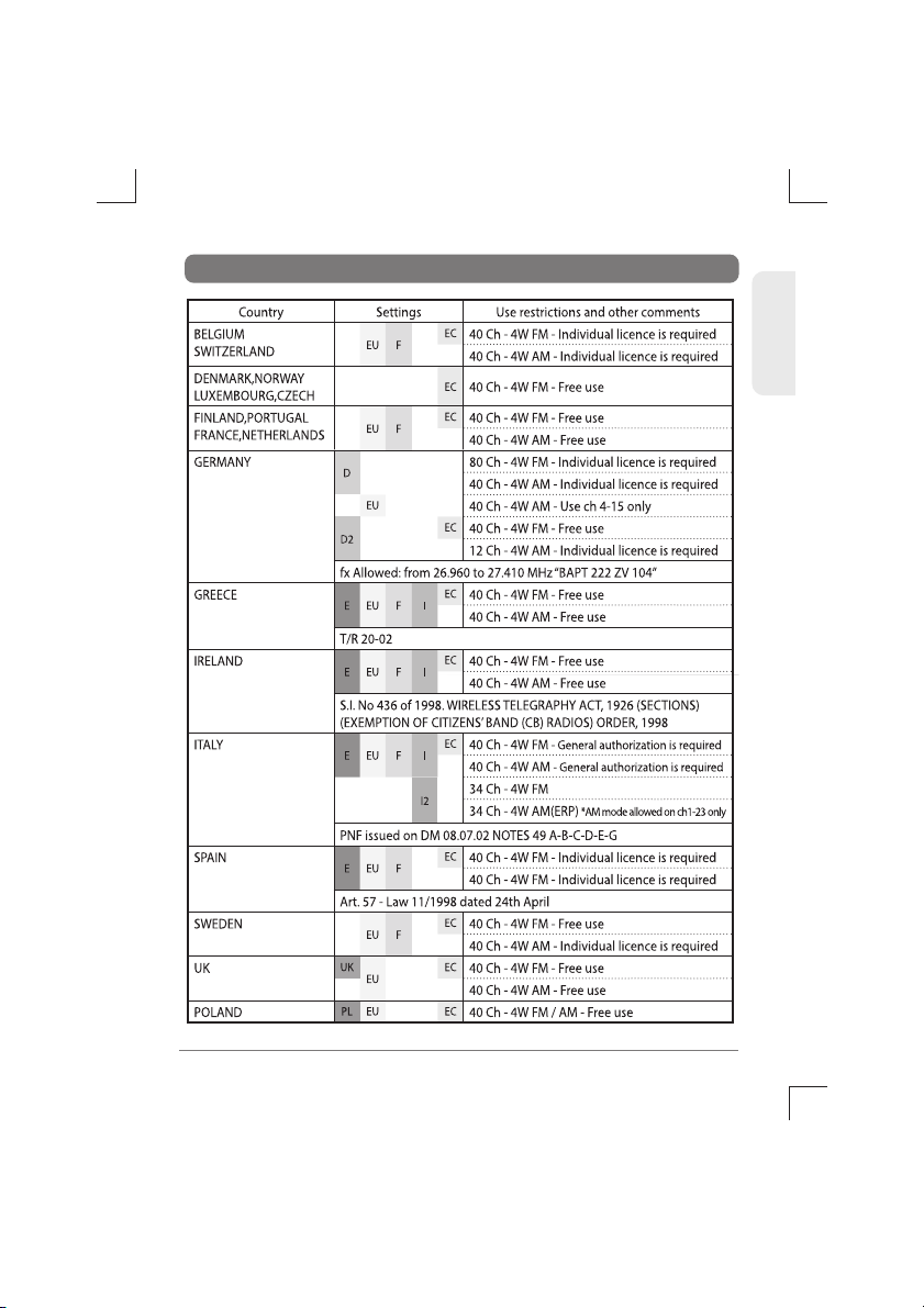
14. Restrictions on the use
16 TCB-550N
ENGLISH
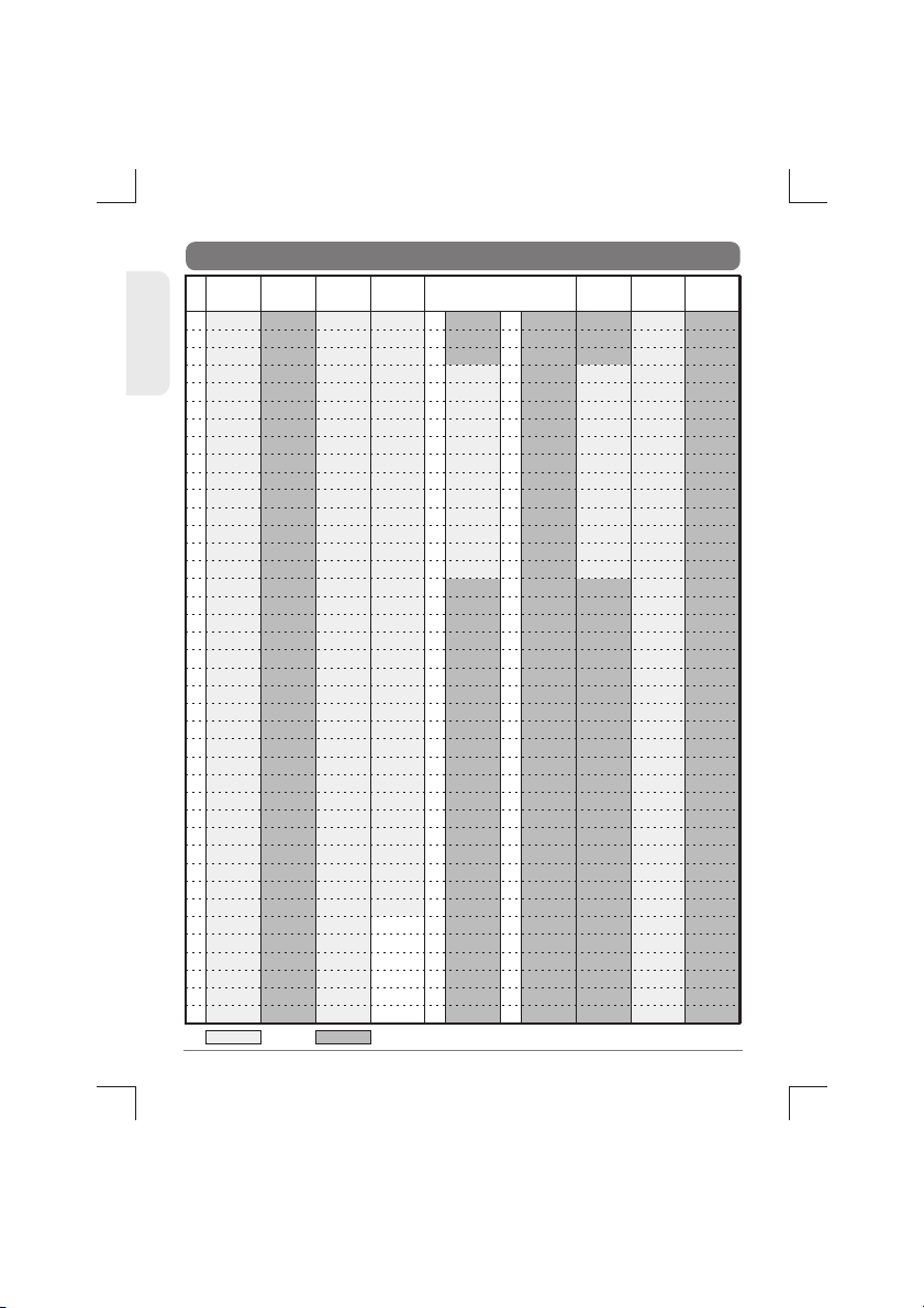
15. Frequency Table
1
2
3
4
5
6
7
8
9
10
11
12
13
14
15
16
17
18
19
20
21
22
23
24
25
26
27
28
29
30
31
32
33
34
35
36
37
38
39
40
26.965
26.975
26.985
27.005
27.015
27.025
27.035
27.055
27.065
27.075
27.085
27.105
27.115
27.125
27.135
27.155
27.165
27.175
27.185
27.205
27.215
27.225
27.255
27.235
27.245
27.265
27.275
27.285
27.295
27.305
27.315
27.325
27.335
27.345
27.355
27.365
27.375
27.385
27.395
27.405
26.965
26.975
26.985
27.005
27.015
27.025
27.035
27.055
27.065
27.075
27.085
27.105
27.115
27.125
27.135
27.155
27.165
27.175
27.185
27.205
27.215
27.225
27.255
27.235
27.245
27.265
27.275
27.285
27.295
27.305
27.315
27.325
27.335
27.345
27.355
27.365
27.375
27.385
27.395
27.405
26.965
26.975
26.985
27.005
27.015
27.025
27.035
27.055
27.065
27.075
27.085
27.105
27.115
27.125
27.135
27.155
27.165
27.175
27.185
27.205
27.215
27.225
27.255
27.235
27.245
27.265
27.275
27.285
27.295
27.305
27.315
27.325
27.335
27.345
27.355
27.365
27.375
27.385
27.395
27.405
26.965
26.975
26.985
27.005
27.015
27.025
27.035
27.055
27.065
27.075
27.085
27.105
27.115
27.125
27.135
27.155
27.165
27.175
27.185
27.205
27.215
27.225
27.255
27.245
27.265
26.875
26.885
26.895
26.905
26.915
26.925
26.935
26.945
26.955
EU/E/F/ UK
(ENG.)
1
2
3
4
5
6
7
8
9
10
11
12
13
14
15
16
17
18
19
20
21
22
23
24
25
26
27
28
29
30
31
32
33
34
35
36
37
38
39
40
26.965
26.975
26.985
27.005
27.015
27.025
27.035
27.055
27.065
27.075
27.085
27.105
27.115
27.125
27.135
27.155
27.165
27.175
27.185
27.205
27.215
27.225
27.255
27.235
27.245
27.265
27.275
27.285
27.295
27.305
27.315
27.325
27.335
27.345
27.355
27.365
27.375
27.385
27.395
27.405
D
41
42
43
44
45
46
47
48
49
50
51
52
53
54
55
56
57
58
59
60
61
62
63
64
65
66
67
68
69
70
71
72
73
74
75
76
77
78
79
80
EC
UK(CEPT)
27.60125
27.61125
27.62125
27.63125
27.64125
27.65125
27.66125
27.67125
27.68125
27.69125
27.70125
27.71125
27.72125
27.73125
27.74125
27.75125
27.76125
27.77125
27.78125
27.79125
27.80125
27.81125
27.82125
27.83125
27.84125
27.85125
27.86125
27.87125
27.88125
27.89125
27.90125
27.91125
27.92125
27.93125
27.94125
27.95125
27.96125
27.97125
27.98125
27.99125
I
26.960
26.970
26.980
27.000
27.010
27.020
27.030
27.050
27.060
27.070
27.080
27.100
27.110
27.120
27.130
27.150
27.160
27.170
27.180
27.200
27.210
27.220
27.250
27.230
27.240
27.260
27.270
27.280
27.295
27.300
27.310
27.320
27.335
27.340
27.350
27.360
27.370
27.380
27.390
27.400
PLI2
26.965
26.975
26.985
27.005
27.015
27.025
27.035
27.055
27.065
27.075
27.085
27.105
27.115
27.125
27.135
27.155
27.165
27.175
27.185
27.205
27.215
27.225
27.255
27.235
27.245
27.265
27.275
27.285
27.295
27.305
27.315
27.325
27.335
27.345
27.355
27.365
27.375
27.385
27.395
27.405
D2
AM/FM FM
26.565
26.575
26.585
26.595
26.605
26.615
26.625
26.635
26.645
26.655
26.665
26.675
26.685
26.695
26.705
26.715
26.725
26.735
26.745
26.755
26.765
26.775
26.785
26.795
26.805
26.815
26.825
26.835
26.845
26.855
26.865
26.875
26.885
26.895
26.905
26.915
26.925
26.935
26.945
26.955
The factory can limit the frequency ranges on request for
sales to certain countries.
TRANSCEPTOR CB-27MHZ
55 N

1) Toma micrófono……………………….6
2) Volumen y puesta en marcha ON/OFF...6
3) LCD Display…………………………….6
4) Control Down canales…………………7
5) Control Up canales……………………..7
6) Tecla AM/FM y Scanner………………...8
7) Canal 9 y 19, y bloqueo…… …………..8
8) Control Squelch………………………..8
9) Conector antena……………………….8
10) Toma alimentación 13,2 DC…………..8
11) Toma altavoz exterior………………....9
INDICE
3
3
3
6
1.
2.
3.
4.
9
9
10
11
11
12
13
13
14
15
16
Introducción
Accesorios en dotación
Instalación
Comandos y funciones
5. Display LCD
6. Microfono
7. Menú ajustes
8. Uso del equipo
9. Selección de bandas
10. Guía de averías
11. Declaración CE
12. Requerimientos de seguridad
13. Especificaciones
14. Restricciones al uso
15.Tabla de frecuencias
SPANISH
Este equipo está marcado con el símbolo de clasificación selectiva relativa a los
desechos de equipos eléctricos y electrónicos. Esto significa que este equipo debe ser
eliminado mediante un sistema de recogida selectiva conforme a la Directiva
Europea 2002/96/CE ya sea con el fin de poder ser reciclado o bien desmantelado
para reducir cualquier impacto en el medio ambiente. Para más información,
consulte con su vendedor o su administración local o regional.
Los aparatos electrónicos que no hayan sido recogidos de forma selectiva son potencialmente
peligrosos para el medio ambiente y la salud pública debido a la posible presencia de sustancias
peligrosas. Los embalajes inservibles recíclelos depositándolos en los contenedores adecuados.

SPANISH
1. INTRODUCCION
TCB-550N receptor-transmisor con cable DC 1 pieza
Micrófono con cable 1 pieza
Soporte para la instalación de la radio 1 pieza
Tornillo mariposa, junta de goma 2 piezas
Tornillo con junta de goma 3 piezas
Tornillo con junta goma (soporte micro) 2 piezas
Soporte de micro 1 pieza
2. ACCESORIOS EN DOTACION
3. INSTALACION
El receptor-transmi
sor T
CB-550N
ha sido diseñado para suministrar
buenos rendimientos en cualquier condición de funcionamiento
gracias a su bastidor recubierto, a su PCB y a sus componentes. Además
este equipo es muy cómodo de utilizar debido a la forma ergonómica
con la cual ha sido concebido y que ha permitido posicionar las
manoplas y las teclas en los sitios más idóneos y correctos. Gracias a la
combinación entre manoplas y teclas bien diseñadas y diseños
gráficos de fácil lectura, los usuarios aprenderán pronto a utilizar
fácilmente el equipo. La nueva modalidad del Menú satisfacera a los
amateurs y profesionales de la radio. La elegante y refinada luz azul del
LED es apta para cualquier vehiculo.
Este manual de uso ha sido concebido, para permitir un mejor manejo
del equipo CB, por lo tanto aconsejamos de invertir algunos minutos
en la lectura de este manual, antes de utilizar por primera vez el equipo
CB.
Este receptor-transmisor esta dotado de una amplia gama de
accesorios para ayudar a los usuarios a empezar a utilizar y sacar el
maximo provecho de todas sus funciones.
Seleccionar primeramente el lugar en el cual vamos a instalar el
receptor-transmisor y el micrófono, de manera que podamos utilizar
cómodamente el aparato. El equipo puede ser instalado tanto en posi-
ción horizontal como en vertical.
El soporte suministrado con el equipo puede ser instalado por debajo
3
TCB-550N

del equipo de manera que el TCB-550N quede sostenido por el soporte
o pueda ser colgado al mismo.
El equipo tiene que ser colocado en un sitio que no obstaculice al
conductor ni a los pasajeros. Seleccionar un sitio en el cual sea posible
un fácil acceso al micrófono y a todos los dispositivos de control.
1)
2)
3)
Colocar el soporte de armado en el sitio en el cual se instalara el
aparato.
Hacer agujeros con un taladro y sujetar el soporte armado.
Conectar el conector del cable de la antena al conector Standard del
equipo marcado "ANT".
4)
Conecte la radio usando el encendedor incluido
5)
6)
Montar el soporte del micrófono, sobre uno de los lados del equipo
o al lado del mismo con los tornillos suministrados junto al equipo.
Conectar el micrófono al equipo, ahora su receptor-transmisor esta
listo para ser usado.
SPANISH
4TCB-550N
Table of contents
Languages:
Other TTI Transceiver manuals

TTI
TTI TCB-550 User manual

TTI
TTI PMR-506TX User manual

TTI
TTI TCB-771 User manual

TTI
TTI TCB-900 User manual

TTI
TTI Freequency PMR-500TX User manual

TTI
TTI TCB-R2000 User manual

TTI
TTI Freequency TCB-770 User manual

TTI
TTI TX-1446 Plus User manual

TTI
TTI Freequency TCB-880 User manual

TTI
TTI TCB-660 User manual


Popular Transceiver manuals by other brands

aci
aci MOD9200BNT user manual

Technisonic Industries Limited
Technisonic Industries Limited TiL-90-6R/8.33 Installation and operating instructions

Icom
Icom IC-U11 instruction manual

Uniden
Uniden ATLANTIS250 BK - ATLANTIS 250 VHF Radio Guide d'utilisation

Kenwood
Kenwood TK-3000 Service manual

Airline
Airline DB038 manual


