elero sonneboy Guide

»sonneboy«
"The intelligent weather monitor”
No programming, no adjusting.
Install, connect, ready to go.
GB-1 109.55012/0801
Installation and
connection instructions

Contents
Page
Explanation of display and keys.............................................................................. 3
General ...........................................................................................................................
Technical data ..............................................................................................................
Assembly and connection......................................................................................... 5–8
Fitting accessories....................................................................................................... 9–10
Operation........................................................................................................................ 11
Setting ranges............................................................................................................... 12
Explanation of Prog key ............................................................................................. 13
Programming................................................................................................................. 13–1
Changing light values ................................................................................................. 13
Changing temperature value .................................................................................... 13–1
Changing wind value................................................................................................... 13–1
Changing pulse duration ........................................................................................... 13–1
Changing delay times ................................................................................................. 13–1
Menu selection ............................................................................................................. 15
Programming protection ............................................................................................ 15
Programming menus................................................................................................... 15
View program................................................................................................................ 16
Delete program............................................................................................................. 16
Programming intermediate position/turning point ............................................. 16
Deleting intermediate position/turning point........................................................ 17
Automatic test for light value..................................................................................... 17
Troubleshooting ........................................................................................................... 18
2

3
Explanation of display and keys
No. Function
1[UP ▲] command key
a) manual „Up“
b) setting figures in
programming mode (plus)
2[DOWN ▼] command key
a) manual „Down“
b) setting figures in
programming mode (minus)
3[Prog] key
Calling up and interrupting
program
4[ENTER] key
Confirmation of programming
(in programming mode)
5[AUTO] key
Automatic/manual mode
6Unassigned key
7Display
Automatic On/Off
No. Function
8Display for rain
9Display for top end position
(TEP)
0Up/Down command key
ßDisplay, brightness value
exceeded
“[C] key (in conjunction with
[DOWN ▼] key) to set
thresholds and times
in basic program
„Display, set wind
value exceeded
”[Free] key
programming protection
¿Display for temperature
value (appears only if
temperature control is
active)
¸Display for brightness value
qDisplay for wind value
Auto Prog
ESO
Menu
Thresholds
Times
Enter
Auto
Free

1. General
The microprocessor-controlled elero sonneboy with rain sensor
input is a compact control unit for electric sunshade systems like
venetian blinds, awnings and blackout blinds.
The automatic control system controls the system automatically as
a function of light intensity (sunshine), wind and rain (snow).
There is also the option of controlling shade as a function of
temperature using the integrated temperature sensor (located on
the board).
This is an especially useful facility in conservatories for saving
heating costs. The wind monitor takes precedence over the light
sensor and the rain monitor and also in automatic and manual
operation so that the sunshade system is reliably protected from
damage. The rain monitor takes precedence only over the light
sensor and only works in automatic mode. Once the wind monitor
has responded, the sunshade system cannot be actuated for at
least the set pulse duration (30 sec.- 3 min.).
The "sonneboy has a basic program in which light value,
temperature, wind value, pulse duration and delay time are all
pre-programmed, i.e. the automatic sunshade system can be
started without being programmed.
If you would like to set different values for brightness, temperature,
wind, pulse duration or delay time, proceed as per Section 8.
2. Technical data
●Voltage: 230 V AC
●Frequency: 50 Hz
●Power draw: ,5 mA
●Switching current: 3 A, cos ϕ= 0,6
●Rupturing capacity: 690 VA
●Output: 2 relays (make contacts) potential-free
●Input: light sensor, wind monitor, rain monitor and
external switch
●Pulse duration: 30 sec. to 3 min. (adjustable)
●Ambient temperature: –5 °C to + 50 °C
●Type of protection: IP 20
●Installation location: Dry areas (do not fit outdoors)
●Basic program: light value for extend 5, for retract ,
temperature "- -", wind value 3, pulse
duration 3 min. and delay time for extend 5,
for retract 10 are pre-programmed.
These values can also be changed
3. Assembly and connection
Work on the mains may be performed only by authorised
specialists
When connecting the wires for mains and protective low voltage
(sensors, external switches), VDE 0100 Part 10 and the assembly
instructions should be observed.
●Switch off mains power
●Connect as per wiring diagram
●Fit light sensor, wind monitor and rain monitor as per Section ,
fit following the relevant instructions
●Clip terminal cover onto (8-pin) connecting terminal
●The power unit is fixed in position using 2 expanding binders or
using mounting screws
●Clip cover onto control panel (see series of diagrams below)
●Plug on control panel
●Switch on power
●Set manual mode using "Auto On/Off” key. "Manual” appears on
the display (manual mode is set on delivery).
●Using the vor bkey, check direction of rotation of the motors.
Important Key vsunshade system must retract
Key bsunshade system must extend
●If the direction of rotation of the motors does not agree with the
vand bsymbols on the control panel, switch off power and
change over wires a vand bterminals of the power unit, then
switch power back on.
5
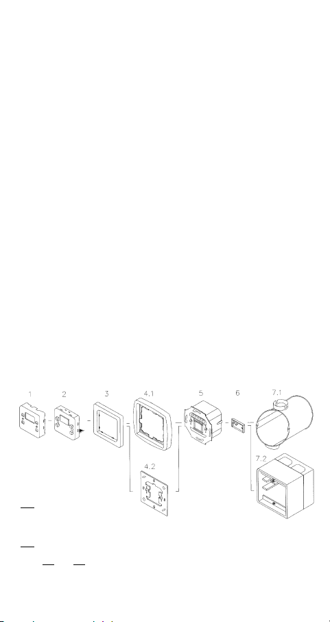
Series of diagrams for assembly (representation applies to any
model)
1: Cover
2: Control panel
3: Adapter frame
.1: Frame
.2: Bearing ring
5: Power unit
6: Terminal cover
7.1: Branch box l60, No. 13 701.5101
7.2: Surface socket, No. 2 8 3.0103 or No. 2 752.0001
Parts .2 and 7.2 replace parts .1 and 7.1 in the case of surface mounting.
Always put parts 1 and 2 together first when assembling.
6
Important notes:
When connecting the light sensor, check the connection is
correct (1-1, 3-3)!
If the light sensor is connected with incorrect polarity, brightness
value 12 appears in the display.
The connection wires to the light sensor, wind monitor and rain
monitor must always be executed as a shielded cable;
either a separate 2-wire line or -wire shared line, e.g. Siemens
LSYCY MSR control line or JY-ST-Y 2 x 2 x 0.6 telecommunicati-
ons line
●Only 1 wind monitor per "sonneboy” may be connected between
terminals 2 and 3.
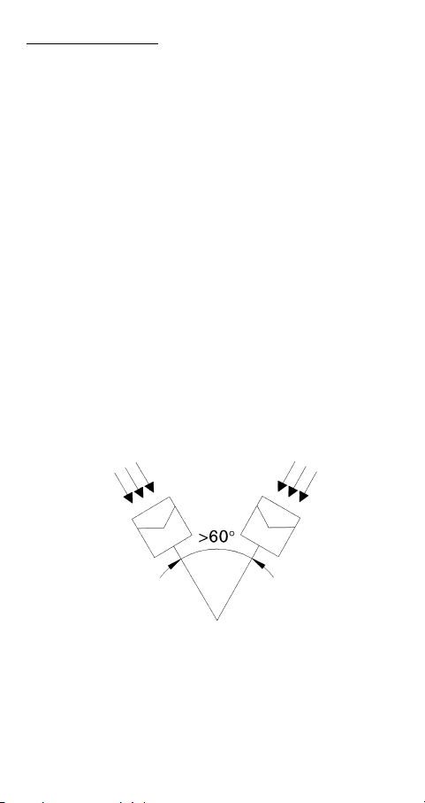
●A second light sensor can be connected between terminals
and 6 to increase the angle of incidence. No account need be
taken of the angle of incidence of the sunlight (for connection,
see Page 8).
●If it is not possible to connect a second light sensor between
terminals and 6 because there are insufficient wires, it is also
possible to connect the second light sensor in parallel with the
first one between terminals 1 and 3.
The light sensors may not be fitted in the same angle of incidence
of sunlight, however, they must be offset by at least 60° (see dia-
gram below). Furthermore, the light value needs to be set at least
2-3 levels higher than in the basic programme.
Light
sensor
7
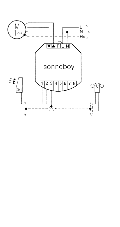
Wiring diagram
Connection max. 1 motor
Do not connect with power switched on!
Attention: you must observe the correct polarity when connecting
the light sensor
Additional control units are required to connect several motors or
switching points.
To do this, please ask for elero control documentation.
Note:
When a temperature level is set, the light sensor only becomes
active once the set level has been exceeded.
A second switching point (individual switch) can be connected for
individual operation. This is given equal priority to the functions of
the [UP] and [DOWN] keys on the control panel and is thus also
only active in manual mode (for connection, see Page 8).
UP
DOWN
blue
green/yellow
Mains
230 V/50 Hz
light
sensor wind
monitor
red
white
black
white
8
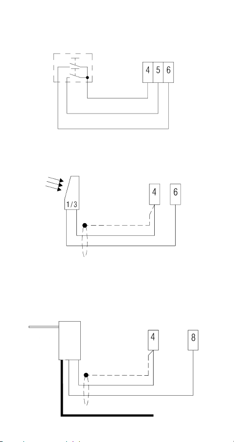
Connecting a switch
Attention: switch only works in "manual” mode.
Connecting a second light sensor
(to increase angle of incidence)
Note: either a switch or a second light sensor can be connected.
It is not possible to connect both at once.
Connecting a rain monitor
The rain monitor retracts the system if it rains (v).
White
red
Mains
230 V/50 Hz
vb
Switch

9
4. Fitting accessories
Light sensor and wind monitor combined
●Fit light sensor and wind monitor vertically, close to the awning
(see Fig.) where sun shines and not in the lee of the wind.
Ensure that no shadows (e.g. from a tower or masts) and no
reflections fall on the light sensor.
●Connect as per wiring diagram (see Page 7).
●Clip on cover and/or unscrew (execution Aero).
Wind monitor
●Fit wind monitor close to the awning, not in the lee of the wind.
●Check correctly positioned (see Fig.).
●Connect as per wiring diagram (see Page 7).
●Clip on cover.
Aero

10
Light sensor
●Attach light sensor vertically (cable inlet underneath) above the
awning with two screws (max. diameter ) in an area where sun
shines.
Ensure that no shadows (e.g. from a tower or masts) and no
reflections fall on the light sensor.
●Connect as per wiring diagram (see Page 7/8).
●Clip on hood.
Note: functions only in automatic mode
Rain monitor
●Fit rain monitor vertically (cable inlet underneath) above the
sunshade system (unprotected).
●Connect as per wiring diagram (in cover): make contact /6
(see Page 8).
●Screw on cover.
Note: functions only in automatic mode

5. Operation
11
Operating modes: manual mode (see Section 5.1)
automatic mode (see Section 5.2)
Numerical display: the first two figures (smaller figures) indicate
the currently-measured temperature value,
the next 2 figures indicate the light value and
the last two figures indicate the currently-
measured wind value.
5.1 Manual mode
The sunshade system cannot be extended manually if the set wind
value is exceeded. In normal conditions, the system can be operated
by hand at any time, as long as the operating mode is set to "Manual”. It
should be noted that when the Up or Down key is operated for less
than 1 second, short pulses are issued (inching mode). If the Up or
Down key is operated for longer than 1 second, the system operates
continuously.
Key: press "Auto On/Off”
"HAnd”(manual) and "Auto Off” symbol
appears
Function: Up: press ▲key
Stop: press ▼key briefly.
Function: Down: press ▼key
Stop: press ▲key briefly.
5.2 Automatic mode
Key: press "Auto On/Off”
"HAnd"(manual) goes out and "Auto On”
symbol comes on
Unless otherwise programmed, the sunshade system is
controlled in accordance with the set light and wind
values any by the rain monitor.
If the wind value is exceeded, it is not possible to
execute a manual Stop command.
●If the light or wind value is exceeded, the symbols
for sun or wind appear and flash in the display.
●If the temperature value is exceeded, the first two
figures (smaller figures) flash in the display.
●If the rain monitor is activated, 7 bars appear and
flash in the display.
The light sensor and the rain monitor only work in automatic mode.
In automatic mode, a command to raise the sunshade is auto-
matically given for safety reasons after power is reinstated after a
cut.

6. Setting ranges
12
Light value level 1–1 (adjustable)
level 1 approx. klx. – low brightness
level 1 over 50 klx. – bright midday sun
Basic program
retract level approx. 15 klx.
extend level 5 approx. 18 klx.
Note: The light values for extending and retracting can be set
differently, but the level for retracting can never be set to be greater
than the level for extending
Temperature value level 1 – 1 bzw. "- -" (adjustable)
level 1 approx. 17°C
level 1 approx. 30°C
Basic program - - (not temperature-controlled)
Note: if shade is to be controlled as a function of
temperature, select the desired level instead
of " - - "when programming.
Wind value level 1 – 9 (adjustable)
level 1 light breeze
level 9 storm
Basic program level 3
Attention: if the wind value is set too high, there is a risk of the
sunshade system being destroyed.
Pulse duration level 00: 30 – 03: 00 (adjustable)
level 00: 30 = 30 sec.
level 03: 00 = 3 min.
Basic program level 03: 00 = 3 min.
Delay time level 5 – 30 (adjustable)
for the light value level 5 = 5 min.
level 30 = 30 min.
Basic program
extend level 5 = 5 min.
retract level 10 = 10 min.
Note: the delay times for extending/retracting can be set differently.

13
7. Explanation of Prog key
By pressing the "Prog” key, you can select one after the other the
input options for values which can be altered for menus, thresholds
(sun, temperature and wind) and times (pulse duration and delay
times).
The "Prog” key only works if the "Free” symbol is being displayed
(see programming protection, Page 15). The "Free” symbol is dis-
played on delivery.
Notes:
1. Using the "Prog” key, you can call up a program step or interrupt
programming at any time.
2. It is not possible to initiate any manual "Up” or "Down” commands
during programming.
3. If programming is interrupted for over 5 min., the operating state
display reappears.
Repeat programming if necessary.
. Input not confirmed with "Enter” is considered not entered and the
previously-entered value is retained.
8. Programming
If the basic program set at the factory is to be changed, the following
steps are required.
Example setting: sun extend 7, sun retract 6, temperature 7, wind 2,
pulse duration 1 min. 30 sec., delay time extend 10 min., delay time
retract 20 min.
Programming thresholds
Key: press "Prog” 2x
Thresholds symbol flashes
Key: press "Enter” 1x
Display is activated
Two right-hand figures: set light value
(extend) flashes
Two left-hand figures: currently-measured
light value
Key: ▲or ▼, set desired light value for
extend.
Key: "Enter" to confirm light value (extend).
Two right-hand figures: set light value
(retract) flashes
Two left-hand figures: currently-measured
light value
Key: ▲or ▼, set desired light value for
retract.

1
Key: Enter”, confirms light value (retract).
Two right-hand figures: set
temperature value flashes
Two left-hand figures: currently-measured
temperature value
Key: ▲or ▼to set desired temperature value.
Key: "Enter” to confirm temperature value.
Two right-hand figures: set wind
value flashes
Two left-hand figures: currently-measured
wind value
Key: ▲or ▼, set desired wind value.
Key: "Enter” to confirm wind value.
Currently-measured temperature,
light and wind values appear.
Programming is complete
Programming times
Key: press "Prog” 3x flashes
Times symbol flashes
Key: press "Enter" 1x
Display is activated
figures: set pulse
duration flashes
Key: ▲or ▼to set desired
pulse duration.
Key: "Enter” to confirm pulse duration.
2 figures: set delay time
(extend) flashes
Key: ▲or ▼to set desired delay time for
extend.
Key: "Enter” to confirm delay time (extend).
2 figures: set delay time
(retract) flashes
Key: ▲or ▼, set desired delay time for
retract.
Key: "Enter” to confirm delay time (retract).
Currently-measured temperature,
light and wind values appear.
Programming is complete.

15
9. Menu selection
It is possible to select one of the 3 menus specified by the factory so
that not all the values have to be adjusted individually.
Menu 1 (e. g. awnings) Basic program
Light value extend level 5 Wind value level 3
Light value retract level Delay time extend 5 min.
Temperature - - Delay time retract 10 min.
Menu 2 (e.g. Venetian blinds)
Light value extend level Wind value level
Light value retract level Delay time extend 5 min.
Temperature - - Delay time retract 20 min.
Menu 3 (e.g. for sunshades in conservatories)
Light value extend level 5 Wind value level
Light value retract level Delay time extend 5 min.
Temperature level 6 Delay time retract 15 min.
10. Programming menus
Key: press "Prog” 1x
Menus symbol flashes
Key: press "Enter" 1x
Display is activated
2 figures: 00 flashes (last values set)
Key: ▲or ▼set desired
menu (e.g. Menu 3)
Key: "Enter” to confirm menu.
Currently-measured temperature,
light and wind values appear.
Programming is complete.
The individual values (thresholds and times) in the menu can be
changed ‚(see Programming) or viewed (see View program).
11 . Programming protection
If you would like to protect the control system from
unintentional programming, deactivate the "Free”
symbol.
Key: press "FREE" 1x
If you like to release the programming,
you should press the "FREE-sign".
Key: press "FREE" 1x

16
12. View program
Identical to programming item 8, but without modifying the values.
13. Delete program
Press key "C” with a ball-point pen or similar object. The display
goes out. Also press the [DOWN] key.
Then release "C” key (full display appears for approx. 2 sec.).
After the full display has gone out, "clr” appears. Then likewise
release the [DOWN] key.
After the program has been deleted, reprogrammed light, temperatu-
re, wind and delay values and intermediate position/turning point are
deleted and the basic program is active again (Menu 1).
The currently-measured light and wind value appear
14. Programming intermediate position/
turning point
Note:
Programming an intermediate position or turning point is possible
only in manual mode (for explanation of operation/manual mode,
see Page 11).
Programming an intermediate position
The "intermediate position” function (only possible when straight)
allows the sunshade system to be positioned in an intermediate
position.
●Press [Up] key and wait for "FTP” symbol
(see explanation on "FTP”, Page 17).
●Press [Up] key and [Down] key simultaneously
for at least 3 seconds.
●Press [Down] key until the desired position is reached and then
also press the [Up] key in this position (this stores the position).
●Release both keys.
Programming the turning point of a Venetian blind
The "turning point” function is for setting an automatic oblique angle
of the slats.
●Press the [Up] key and wait for the "FTP” symbol (see explanation
of "FTP”, Page 17).
●Press [Up] key and [Down] key simultaneously for at least
3 seconds.
●Press [Down] key until the desired position is reached and then
also press the [Up] key several times in this position. This angles
the slats to the desired oblique angle
●Release both keys (this stores the position).

Notes:
The programmed intermediate position and/or turning point is only
reached from the ESO-position meaning that the impulse time of the
last "UP” command has expired.
– When the intermediate position/turning point starts up, direction
arrow bor vflashes.
– It is possible to extend the shade completely from the program-
med intermediate position/turning point by giving another
"DOWN” command.
Delete intermediate position/turning point
●Press [Up] key and wait for "FTP” symbol
(see explanation on "FTP” below).
●Press [Up] key and [Down] key simultaneously for at least
3 seconds. (Deletion is automatic when both keys are pressed).
Explanation of "FTP : the symbol "FTP” appears once the pulse
duration of the Up command has elapsed, when the [UP v] key is
pressed (only possible in manual mode) or after an automatic [UP v]
command. (Depending on the pulse duration set, between 30 sec.
and 3 min.)
15. Automatic test for light value
The automatic test is an installation aid and enables the sun function
to be tested quickly. The minutes set as the delay time are converted
into seconds for this purpose.
Start automatic test
The blind must be pulled right up, the control must be on Auto
"ON” and the "FTP” symbol must have appeared (see explanation
of "FTP”).
If these conditions are met, the "Unassigned” and [AUTO] keys must
be pressed simultaneously. Activation is shown by the "FTP” symbol
flashing.
If the light value for pulling out exceeds the period of the delay time
(in seconds) the blind goes out. When after going out the light value
on the light sensor descends below the programmed light value for
the entry for the period of the delay time (in seconds) the blind
goes in.
Switch off automatic test
The installation aid is automatically switched off once "FTP” is
reached again.
17

18
Fault Cause Remedy
Motor not running L-P bridge missing Pinch in L-P bridge
(p. 7)
Motor running in Incorrect connection Switch ▲and ▼wires on
wrong directuon power unit (p. 6)
Motor fails to run Intermediate position Delete intermediate position
right to bottom programmed (p. 17)
Intermediate 1.) Sunshade system not 1.) Move sunshade system
position cannot be in top end position (FTP) up and wait until “FTP”
programmed symbol is displayed
(p. 17)
2.) Old intermediate 2.) Delete intermediate
position not deleted position (p. 17)
3.) Manual mode not set 3.) Switch off automatic
(p. 11)
Intermediate Sunshade system Move sunshade system
position cannot not in top end position up and wait until
be deleted (FTP) “FTP” symbol is
displayed (p. 17)
Sunshade system 1.) Sunshade system 1.) Move sunshade system
does not run down, is not in top end up and wait until “FTP”
although “sun” position (FTP) symbol is displayed
symbol is flashing (p. 17)
2.) Automatic mode 2.) Switch on Automatic
not switched on (p. 11)
3.) Delay time has not 3.) Wait for delay time
yet elapsed (p. 12)
.) Set temperature .) Wait for temperature
value not yet reached to rise, possibly reduce
or switch of temperature
level (p. 12)
Sunshade system 1.) Set wind value 1.) Wait for wind to
goes up, although exceeded drop (p. 12)
the “sun” symbol 2.) Set temperature 2.) Wait for temperature
is flashing value not reached to rise, possibly reduce
or switch off temperature
level (p. 12)
Brightness value Light sensor Switch connections
in display for sun connections are back (p. 7)
is on 12, although to front
sun is not
shining
System does not Light sensor is shade Position light sensor
extend in spite of (too little sun) elswhere
bright light
Troubleshooting

19
Notes

20
Notes
Table of contents
Popular Weather Station manuals by other brands

La Crosse Technology
La Crosse Technology 308-1415V3 Setup guide

BASETech
BASETech 310 operating instructions

Inovalley
Inovalley RPM10 owner's manual

Oregon Scientific
Oregon Scientific BAR112HGLA user manual

Oregon Scientific
Oregon Scientific Monza FAW-101 user guide

Hyundai
Hyundai WS 1070 instruction manual

EIJKELKAMP
EIJKELKAMP WS-GP2 quick start guide

ACU-RITE
ACU-RITE 02038 instruction manual

La Crosse Technology
La Crosse Technology WIRELESS 868 MHz instruction manual

Hyundai
Hyundai WSC 2907 instruction manual

Oregon Scientific
Oregon Scientific BAR989HG user manual

Hyundai
Hyundai WSC 1909 instruction manual


