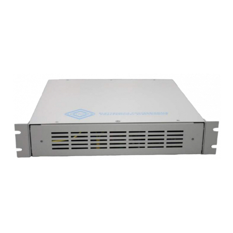
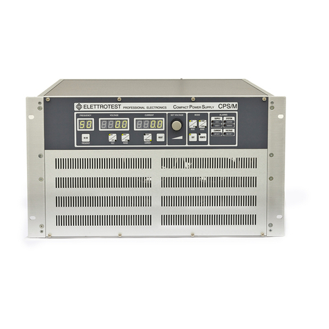
Elettrotest RPS User manual

1
USER MANUAL RPS/M/1K
Elettrotest S.p.A. P.zza R. Riello, 20/B - 45021 Badia Polesine ( RO ) - tel. +39 0425 53567 - Fax +39 0425 53568
e-mail: info@elettrotestspa.it http: www.elettrotestspa.it
62000582 Rel.1.0 –15/03/2018
1. RACK POWER SUPPLY……………………………………………………………………………………………....2
1.1. GENERALITY……………………………………………………………………………………………………...2
1.1.1. INTRODUCTION……………………………………………………………………………………....2
1.1.2. SAFETY WARNINGS…………………………………………………...………………………..…..2
1.1.3. RISK TYPOLOGY……………………………………………………………………………………....3
1.2. VOLTAGE OUTPUT………………………………………………………….......……………………………3
1.3. FREQUENCY OUTPUT……………………………………………………….……..............................4
1.4. USER INTERFACE……………………………………………………………………..............................4
1.5. MODELS……………………………………………………………………………..…...............................4
1.6. GENERAL PERFORMANCES………………………………………………………..………………………5
1.7. GENERAL SPECIFICATIONS…………………………………………………………………………………5
1.8. MAXIMUM OUTPUT CURRENT…………………………………………………….........................5
1.9. NOTES FOR THE INSTALLATION………………………………………………………………………….6
1.9.1. RPS/M/1K………………………………………………………………………………………………..6
2. NOTES FOR USERS…………………………………………………………………………………………………….8
2.1. SWITCHING ON…………………………………………………………………........……………………….8
2.2. VOLTAGE FEEDBACK………………………………………………………………………………………….8
2.3. LIMITATION CURRENT MODE…………………………………………………...……………………….9
2.3.1. LIMITATION SETTING……………………………………………………………………………..10
2.3.2. RPS1000…………………………………………………………………………………………………11
2.4. OUTPUT RELAY………………………………………………………………...……............................11
2.5. ALARMS……………………………………………………………………………...…………………………..12
2.5.1. SUPPLY ALARMS…………………………………………………………..….........................12
2.5.2. SYSTEM ALARMS………………………………………………………..………………………….12
2.5.3. CURRENT ALARM……………………………………………………...…………………………..12
2.5.4. VOLTAGE ALARM……………………………………………………...…..……………………...13
3. SERIAL REMOTE CONTROL...…………………………………………………...……………………………..13
3.1. CONTROL SOFTWARE ……………………………………………………...……………………………..13
3.2. SERIAL CABLE……………………………………………………………...…………………………………..13
4. ANALOG REMOTE CONTROL………………………………………………...………………………………..14
4.1. ANALOG INTERFACE……………………………………………………………....……………………….14
4.2. PERFORMANCES…………………………………………………………………….............................15
5. POWER SUPPLY CONNECTION…………………..……………………………………..........................16
5.1. FUSES……………………………………………………………………………….…...............................16
5.2. RCD PROTECTION…………………………………………………………………………………………….16
5.3. MAGNETO THERMAL PROTECTION………………………………………………………………….16
5.4. WIRING DIAGRAM………………………………………………………………..…..........................17
6. MECHANICAL DRAWING……………………………………………………………….............................18

2
USER MANUAL RPS/M/1K
Elettrotest S.p.A. P.zza R. Riello, 20/B - 45021 Badia Polesine ( RO ) - tel. +39 0425 53567 - Fax +39 0425 53568
e-mail: info@elettrotestspa.it http: www.elettrotestspa.it
62000582 Rel.1.0 –15/03/2018
1. RACK POWER SUPPLY
1.1. GENERALITY
1.1.1. INTRODUCTION
RPS is a power source that supplies a sinusoidal and stable voltage. Its output voltage is adjustable
in frequency and amplitude.
1.1.2. SAFETY WARNINGS
The manufacturer urges users to read the user’s manual for our products carefully before
installation.
The installation must be carried out by qualified technical staff. The non-observance of the
warnings in this manual can cause electric shocks, even fatal ones.
Please find below some general safety warnings.
V GENERAL WARNINGS
This equipment must be connected to the mains supply using the appropriate safety
devices. Please consult the relevant paragraph 5, in this manual.
RPS must be connected to safety ground through the apposite connections. The non-
observance or the degradation of this earth connection can lead to electric shocks, even fatal
ones. As regards the correct connection modes, please refer to the information contained in
paragraph 5.
Disconnect RPS from the mains before any work on the equipment and on the connected
power loads.
Before touching the load or the output connector make sure that the power supply on the
device has been disconnected for at least 5 minutes. This is the time necessary in order for the
capacitors inside the device to discharge. The non-observance of this discharge time can lead
to electric shocks, even fatal ones.
The output of RPS is not isolated respect to the main power supply and so NONE OF THE
TWO OUTPUT PHASES CAN BE CONNECTED TO THE GROUND.
Avoid heavy shocks to the equipment (especially during transport) or exposure to extreme
weather conditions.
Any damage to the product due to transportation, incorrect installation or improper use is
not covered by the guarantee supplied by the manufacturer.
Do not use the equipment in explosive environments or in the presence of dust, acids or
corrosive and/or inflammable gases.
Tampering with or dismantling any component in the equipment will cause the automatic
expiry of the guarantee.

3
USER MANUAL RPS/M/1K
Elettrotest S.p.A. P.zza R. Riello, 20/B - 45021 Badia Polesine ( RO ) - tel. +39 0425 53567 - Fax +39 0425 53568
e-mail: info@elettrotestspa.it http: www.elettrotestspa.it
62000582 Rel.1.0 –15/03/2018
Do not operate or store under conditions where condensing may occur or where
conductive debris may enter in the case.
The manufacturer declines all responsibility for damage to people or things
caused by an improper use of its products.
1.1.3. RISK TYPOLOGY
ELECTRIC RISK
There are dangerous voltages inside RPS and over the output connector.
The non-observance of the warnings suggest in this manual can lead to electric shocks, even
fatal ones.
OVERHEATING RISK
In the case of a ventilation system failure, the metal parts of the inverter may reach high
temperatures (in some cases greater than 70°C).
1.2. VOLTAGE OUTPUT
The output voltage is guaranteed perfectly sinusoidal, with a distortion of less than 0.3%
regardless of the load. The value of output voltage is kept perfectly stable within 0.1% regardless
of the load.
RPS is also able to compensate for possible voltage drops on the output wires, ensuring in this way
the exact voltage you want on the load.
The load that RPS is able to drive can vary from the pure capacity to the pure inductance, but also
up to non symmetrical current loads, as for instance a single half wave rectifier.
The output voltage is adjustable with continuity from zero to full scale. Furthermore RPS is capable
to keep the voltage stable also with time variable loads, as for example the pulsating loads. In fact
RPS recovers the distortion of the waveform within 0.3% and the amplitude of the voltage within
0.1% in less than half period.

4
USER MANUAL RPS/M/1K
Elettrotest S.p.A. P.zza R. Riello, 20/B - 45021 Badia Polesine ( RO ) - tel. +39 0425 53567 - Fax +39 0425 53568
e-mail: info@elettrotestspa.it http: www.elettrotestspa.it
62000582 Rel.1.0 –15/03/2018
Furthermore, RPS can bear a short-circuit for an indefinite time without suffering any
consequence.
ATTENTION !!!!
THE OUTPUT OF RPS IS NOT ISOLATED RESPECT TO THE MAIN POWER SUPPLY
NONE OF THE TWO OUTPUT PHASES CAN BE CONNECTED TO THE GROUND
1.3. FREQUENCY OUTPUT
RPS allows the regulation of the output frequency from 10 Hz to 80 Hz. The output frequency can
be adjusted with continuity into the regulation range and it has a stability of 0.01% regards to set
frequency.
1.4. USER INTERFACE
RPS can be controlled only through copyrighted serial communication protocol.
RPS allows various usage selections: wires drop compensation, working frequency, output DC,
output AC.
RPS gives the user clear information on the status of the output.
It is monitored both the set voltage and the set frequency. The output voltage can be remotely
read with a precision of 0.3%.
The user is also warned in case of overcurrent obtainable by the RPS, or in case of high loss on the
wires, that should not exceed 5% of the set voltage.
1.5. MODELS
The models are different depending on the rated power and the supply mode (single phase or
three phase with neutral).
MODELS
NOMINAL
POWER
SUPPLY
VOLTAGE
WEIGHT
INPUT
CURRENT
DIMENSIONS
A, L, P mm
RPS/M/1K
1.000VA
230Vac ±10%
1PH
12 kg
8.5A
2U : 84 TE : 440

5
USER MANUAL RPS/M/1K
Elettrotest S.p.A. P.zza R. Riello, 20/B - 45021 Badia Polesine ( RO ) - tel. +39 0425 53567 - Fax +39 0425 53568
e-mail: info@elettrotestspa.it http: www.elettrotestspa.it
62000582 Rel.1.0 –15/03/2018
1.6. GENERAL PERFORMANCES
All the following features are valid in the normal operation mode. They are not valid during the
output current limitation.
1.7. GENERAL SPECIFICATIONS
PARAMETER
VALUE
Output frequency range
DC/ 10Hz - 80Hz
Frequency resolution
0.02Hz
Frequency precision and time stability
100ppm
Output voltage at constant power
300V
Output voltage resolution
0.025% f.s. (12 bit su f.s.)
Operating temperature of function
0°C - 35°C
1.8. MAXIMUM OUTPUT CURRENT
PARAMETER
VALUE
Distortion of the output waveform
<0.3%
Stability of the output voltage
<0.1%
Accuracy of the output voltage
<0.5%
Recovery time of the output waveform
<10ms
Recovery-time of the output voltage
<10ms
Maximum compensated drop on wires
5% f.s.
Recovery-time of drop on wires
<200ms.
RPS/M/1K
REGIME CONTINUO/CONTINUOUS OPERATION
CORRENTE MASSIMA\MAX CURRENT
POTENZA MASSIMA\MAX POWER
PORT
DC
50 Hz
60 Hz
LOAD
PORT
DC
50 Hz
60 Hz
LOAD
300
-
2,7 A
2,6 A
CAP.
300
-
811 VA
768 VA
CAP.
300
-
4,1 A
4,3 A
IND.
300
-
1235 VA
1277 VA
IND.
300
3,4 A
3,3 A
3,3 A
RES.
300
1020 VA
1001 VA
991 VA
RES.
REGIME IMPULSIVO (MAX 3 SECONDI)/ IMPULSIVE OPERATION(MAX 3 SECONDS)
CORRENTE MASSIMA\MAX CURRENT
POTENZA MASSIMA\MAX POWER
PORT
DC
50 Hz
60 Hz
LOAD
PORT
DC
50 Hz
60 Hz
LOAD
300
-
6,2 A
6,1 A
CAP.
300
-
1862 VA
1820 VA
CAP.
300
-
7,6 A
7,8 A
IND.
300
-
1235 VA
2329 VA
IND.
300
6,9 A
6,9 A
6,9 A
RES.
300
2064 VA
2064 VA
2059 VA
RES.

6
USER MANUAL RPS/M/1K
Elettrotest S.p.A. P.zza R. Riello, 20/B - 45021 Badia Polesine ( RO ) - tel. +39 0425 53567 - Fax +39 0425 53568
e-mail: info@elettrotestspa.it http: www.elettrotestspa.it
62000582 Rel.1.0 –15/03/2018
1.9. NOTES FOR THE INSTALLATION
1.9.1. RPS/M/1K
Connect one supplying cable 2P+G (standard IEC cable) of suitable section (minimum
section 3x1.5 mm2).
Protect the input line with the circuit breakers presented in paragraph 5.
Connect load cable to the output connector. Use an appropriate sections according to the
maximum load tolerable by the RPS.
Put the ferrite core on the load cable close to RPS.
Optionally: Connect the sense wires.
Keep front area free for ventilation.
When RPS is mounted inside a cabinet you must install a forced ventilation in order to
expel the hot air.
Never lay power cables (including the electrical cables) and probe signal cables in the same
conduits;
Cleaning the device: When cleaning the device do not use ethyl alcohol, hydrocarbons
(petrol), water, detergents, ammonia and derivatives. Use only a dry cloth.
INPUT CONNECTOR
OUTPUT CONNECTOR
FERRITE CORE

7
USER MANUAL RPS/M/1K
Elettrotest S.p.A. P.zza R. Riello, 20/B - 45021 Badia Polesine ( RO ) - tel. +39 0425 53567 - Fax +39 0425 53568
e-mail: info@elettrotestspa.it http: www.elettrotestspa.it
62000582 Rel.1.0 –15/03/2018
INDEX
DESCRIPTION
1
Serial 9 poles connector
2
Power output connector
3
Fan grid
4
Power input connector
5
Earth connector
6
Analog port
7
Ventilation Grill
RPS/M /1K

8
USER MANUAL RPS/M/1K
Elettrotest S.p.A. P.zza R. Riello, 20/B - 45021 Badia Polesine ( RO ) - tel. +39 0425 53567 - Fax +39 0425 53568
e-mail: info@elettrotestspa.it http: www.elettrotestspa.it
62000582 Rel.1.0 –15/03/2018
2. NOTES FOR USERS
2.1. SWITCHING ON
RPS doesn't have power switch and so when the input connector is powered, RPS turns on. RPS
needs (after power on) less than 10 seconds to be ready.
2.2. VOLTAGE FEEDBACK
The output voltage stabilization works the same in both the configurations on the RPS output
terminals (2 wire) and on a possible long distance outlet (4 wire), to compensate the voltage drop
due to cable connections. To work in 4WIRES configuration, you must perform the wiring as shown
in the figure below and set "4WIRE" mode via remote control.
RPS compensates the voltage drop on the connections up to 5% of the set voltage.
To prevent any overheating of the line, when the limit has been exceeded, RPS does not guarantee
that the value of output voltage is equal to the voltage set. In this case it displays an error signal
(see the paragraph VOLTAGE ALARMS).

9
USER MANUAL RPS/M/1K
Elettrotest S.p.A. P.zza R. Riello, 20/B - 45021 Badia Polesine ( RO ) - tel. +39 0425 53567 - Fax +39 0425 53568
e-mail: info@elettrotestspa.it http: www.elettrotestspa.it
62000582 Rel.1.0 –15/03/2018
2.3. LIMITATION CURRENT MODE
With RPS we can set two limitation current mode:
PEAK LIMITATION MODE: Output current is limited instantaneously without delay at the
limitation set. Remain only an initial transient peak due to the output capacitor discharge.

10
USER MANUAL RPS/M/1K
Elettrotest S.p.A. P.zza R. Riello, 20/B - 45021 Badia Polesine ( RO ) - tel. +39 0425 53567 - Fax +39 0425 53568
e-mail: info@elettrotestspa.it http: www.elettrotestspa.it
62000582 Rel.1.0 –15/03/2018
AVERAGE LIMITATION MODE:
Output current is limited with linear trend during a specific time (tAVG) in order to reach the
limitation set. Typical limitation time (tAVG) is 200ms.
Limitations is enable both AC and DC mode
2.3.1. LIMITATION SETTING
Both peak and average limitation can be set via serial command. Limits must be included in the
range [500,4095]. Values less than 500 are considered 500 by default (minimum value).
The factory values for both limitations are 4095. For further information please read the
programming manual.

11
USER MANUAL RPS/M/1K
Elettrotest S.p.A. P.zza R. Riello, 20/B - 45021 Badia Polesine ( RO ) - tel. +39 0425 53567 - Fax +39 0425 53568
e-mail: info@elettrotestspa.it http: www.elettrotestspa.it
62000582 Rel.1.0 –15/03/2018
2.3.2. RPS1000
2.4. OUTPUT RELAY
It’s possible to open or close the output relay both serial command or digital input. Before opening
the relay, the output voltage is switched to zero to safeguard the relay. Similarly, the closing is
done with zero voltage. Later the output will reach the set value through a voltage ramp (set via
serial commands).
The turn off of the output relay does not allow operations on the EUT connections.

12
USER MANUAL RPS/M/1K
Elettrotest S.p.A. P.zza R. Riello, 20/B - 45021 Badia Polesine ( RO ) - tel. +39 0425 53567 - Fax +39 0425 53568
e-mail: info@elettrotestspa.it http: www.elettrotestspa.it
62000582 Rel.1.0 –15/03/2018
2.5. ALARMS
2.5.1. SUPPLY ALARMS
RPS can work with ±10% network voltage variations. If these RPS limits are exceeded, the RPS
stops and a special alarm is generated. In this case RPS can be unlocked via serial command
(SOFTWARE RESET) or by turning the machine off and on again.
If the supply voltage is too low RPS stops and generate UNDERVOLTAGE alarm.
If the supply voltage is too high RPS stops and generate OVERVOLTAGE alarm.
2.5.2. SYSTEM ALARMS
Also in case of hardware failure of the inner inverter RPS stops and generates a special alarm
(INVERTER). To reset RPS use the same method described for supply alarms. In case of high
temperature inside RPS, it stops and a special error is generated (OVERTEMP).
To reset the machine, turn it off and wait for a few minutes to cool the system. After that turn it
on again.
2.5.3. CURRENT ALARM
RPS controls the output current. Therefore RPS support for an indefinite time the output short
circuit. In the case of loads that needs a current higher than the rated, RPS operates an output
current limitation. When this limitation occurs, a special alarm is generated (LIMIT OUT1).
In case of current limitation the output sinusoidal wave is not guaranteed. Output
can present an harmonic distortion.

13
USER MANUAL RPS/M/1K
Elettrotest S.p.A. P.zza R. Riello, 20/B - 45021 Badia Polesine ( RO ) - tel. +39 0425 53567 - Fax +39 0425 53568
e-mail: info@elettrotestspa.it http: www.elettrotestspa.it
62000582 Rel.1.0 –15/03/2018
WIRING CONNESSION
PC RPS
DB9 Poles Female DB9 Poles Male
2 2
3 3
5 5
Nonlinear loads that required a power less than the maximum admitted from RPS with a very high
crest factor current can generate the current limitation.
If RPS is operating in current limitation, it maintains the RMS output voltage equal to the set value
until a special voltage alarm is generated (see VOLTAGE ALARM).
VOLTAGE ALARM does not cause any stop.
2.5.4. VOLTAGE ALARM
RPS controls, in addition to the harmonic distortion, the RMS value of the output voltage both in
2WIRES and in 4WIRES configuration.
If the output voltage is not equal to the set value, a special alarm is generated (MAX DV OUT1).
VOLTAGE ALARM does not cause any stop.
3. SERIAL REMOTE CONTROL
3.1. CONTROL SOFTWARE
RPS can be remotely controlled via RS232 communication according to a defined free protocol. For
further details on protocol, see the specific manual.
Parameters for serial connection:
BAUD RATE: 19200 (in standard version)
DATA BITS: 8
STOP BITS: 1
3.2. SERIAL CABLE
Use a serial cable according to the standard defined in the figure below.

14
USER MANUAL RPS/M/1K
Elettrotest S.p.A. P.zza R. Riello, 20/B - 45021 Badia Polesine ( RO ) - tel. +39 0425 53567 - Fax +39 0425 53568
e-mail: info@elettrotestspa.it http: www.elettrotestspa.it
62000582 Rel.1.0 –15/03/2018
4. ANALOG REMOTE CONTROL
4.1. ANALOG INTERFACE
RPS can be controlled by analog interface:
All the signals in the analog interface (both analog and digital) are referred to GND (9th pin of the
connector).
Input circuit of “Ref analog” signal
Pin
Name
Description
Level
1
+5V
Power supply (Max 40mA)
Respect to GND
2
Ref analog
Pwm or analog input
0-10V (respect to GND)
3
50/60 Hz
Digital input
0V (50Hz) –5V (60Hz)
4
Output relay
Digital input
0V (Off) –5V (On)
5
DC/AC
Digital input
0V (AC) –5V (DC)
6
Alarm
Digital output
0V (no alarm) 5V (alarm)
7
Synchronism
Digital output
Square waveform synchronized to
output voltage (0-5V).
8
Enable
Digital output
0V (not enabled) 5V (enabled)
9
GND
Ground

15
USER MANUAL RPS/M/1K
Elettrotest S.p.A. P.zza R. Riello, 20/B - 45021 Badia Polesine ( RO ) - tel. +39 0425 53567 - Fax +39 0425 53568
e-mail: info@elettrotestspa.it http: www.elettrotestspa.it
62000582 Rel.1.0 –15/03/2018
4.2. PERFORMANCES
Delay time between analog input and RPS output is about 200ms.
DELAY TIME IN DC MODE
Digital input circuit
Digital output circuit

16
USER MANUAL RPS/M/1K
Elettrotest S.p.A. P.zza R. Riello, 20/B - 45021 Badia Polesine ( RO ) - tel. +39 0425 53567 - Fax +39 0425 53568
e-mail: info@elettrotestspa.it http: www.elettrotestspa.it
62000582 Rel.1.0 –15/03/2018
DELAY TIME IN AC MODE
5. POWER SUPPLY CONNECTION
The output of RPS is not isolated respect to the main power supply therefore NONE
OF THE TWO OUTPUT PHASES CAN BE CONNECTED TO THE SAFETY GROUND.
5.1. FUSES
Fuses can be used to protect the power line of the RPS. We recommend to use a delayed fuses
with rated current of 16 ARMS and a rated voltage of 230 VRMS (Both for phase and neutral).
5.2. RCD PROTECTION
Below the recommended RCD protections (Residual Current Device) for the input line. It's
recommended to use B type RCD with a earth leakage current of 30 mA.
5.3. MAGNETO THERMAL PROTECTION
The Magneto-thermal circuit breaker protect the input line from short circuits. Generally depends
on the load and on the connection (section and length of the cable). It is recommended to use a
magneto-thermal protection with type C curve.

19
USER MANUAL RPS/M/1K
Elettrotest S.p.A. P.zza R. Riello, 20/B - 45021 Badia Polesine ( RO ) - tel. +39 0425 53567 - Fax +39 0425 53568
e-mail: info@elettrotestspa.it http: www.elettrotestspa.it
62000582 Rel.1.0 –15/03/2018
Elettrotest Spa is committed to a program of continuous improvement of products and
information to the customer.
Therefore reserves the right to make changes to the documentation and specifications without
notice and assumes no responsibility for any incorrect information.
Rel.
Date
Descriptions
1.0
15/03/18
Analog port implementation
0.0
06/10/17
First revision.
This manual suits for next models
2
Table of contents
Languages:
Other Elettrotest Portable Generator manuals
Popular Portable Generator manuals by other brands
AL-KO
AL-KO 2500-C Translation of the original instructions for use
Millenium Signatures
Millenium Signatures MS-510 instruction manual
Flextool
Flextool DP4 operating instructions
Robin
Robin LG072 Service manual
Onan
Onan Protec Series installation manual
Winco
Winco DR175F4 Installation and operator's manual


