eleXsys EEdS 3042 User manual

V.3.6.3 April 2020
eleXsys Energy User Manual
and Installation Guide
30 kVA Three-Phase EEdS

Commercial-In-Confidence Page 1 of 58 © eleXsys R&D Pty Ltd Apr 2020
Contents
SYMBOLS........................................................................................................................................................................6
1. Product Information ..............................................................................................................................................7
1.1. Scope...............................................................................................................................................................7
1.2. Model ..............................................................................................................................................................8
1.1.1. Tag Information ....................................................................................................................................... 8
1.3. Features...........................................................................................................................................................9
1.3.1. Three-phase or single-phase ...................................................................................................................9
1.3.2. DC voltage range......................................................................................................................................9
1.3.3. Frequency ................................................................................................................................................9
1.3.4. Four quadrant operation .......................................................................................................................10
1.3.5. Phase balancing .....................................................................................................................................10
1.3.6. Battery charging and discharging ..........................................................................................................10
1.3.7. Power conditioning................................................................................................................................10
1.3.8. Harmonic correction..............................................................................................................................10
1.3.9. Current or voltage source inverter........................................................................................................10
1.3.10. Power factor correction .....................................................................................................................10
1.3.11. Power flow regulation........................................................................................................................11
1.3.12. Uninterruptable Power Supply (UPS) –future development............................................................11
1.3.13. Off grid operation –future development..........................................................................................11
1.3.14. Grid Voltage Regulation .....................................................................................................................11
1.4. Communication and Data Logging................................................................................................................12
1.4.1. Communication Interfaces ....................................................................................................................12
1.4.2. Communication protocols .....................................................................................................................12
1.4.3. Data logging ...........................................................................................................................................12
1.5. EEdS30 Specification .....................................................................................................................................13
1.6. Appearance ...................................................................................................................................................15
2. Installation Guide.................................................................................................................................................16

Commercial-In-Confidence Page 2 of 58 © eleXsys R&D Pty Ltd Apr 2020
2.1. Applicable Standards and Guides .................................................................................................................16
2.2. Pre-cautions ..................................................................................................................................................17
2.2.1. Potential Hazards or Injuries .................................................................................................................17
2.2.2. Risks and Safety .....................................................................................................................................17
2.2.3. Working with Batteries..........................................................................................................................18
2.2.4. Labelling of Electrical Apparatus ...........................................................................................................18
2.3. Categorized Installation Components...........................................................................................................20
2.4. Electrical Connections...................................................................................................................................21
2.4.1. EEdS architecture...................................................................................................................................21
2.4.2. Electrical connection diagram ...............................................................................................................22
2.5. Servicing, Storage and Transportation..........................................................................................................23
2.5.1. Important safety instructions ................................................................................................................23
2.5.2. Storage and transportation ...................................................................................................................23
2.6. Installation Procedures .................................................................................................................................24
2.6.1. Installation Environment .......................................................................................................................25
2.6.2. Installation specifications ......................................................................................................................26
2.6.3. Connections ...........................................................................................................................................27
2.6.4. Connections to battery energy system (BES) ........................................................................................29
2.6.5. Detachable parts....................................................................................................................................30
2.6.6. Circuit protection...................................................................................................................................31
2.6.7. Earthing..................................................................................................................................................32
2.6.8. Communications ports...........................................................................................................................32
2.6.9. Auxiliary power connection...................................................................................................................34
2.6.10. Earth fault alarm ................................................................................................................................34
2.7. Commissioning and maintenance.................................................................................................................35
2.8. Start Procedure .............................................................................................................................................35
2.9. Shutdown Procedure ....................................................................................................................................36
2.10. Emergency Shutdown Procedure..............................................................................................................36
2.11. Maintenance..............................................................................................................................................37
2.12. EEdS Configuration....................................................................................................................................37

Commercial-In-Confidence Page 3 of 58 © eleXsys R&D Pty Ltd Apr 2020
2.12.1. Grid Response Mode..........................................................................................................................37
2.12.2. Power Quality Response Mode..........................................................................................................39
2.12.3. Volt-Watt Response Mode (Default) .................................................................................................39
2.12.4. Volt-Var Response Mode ...................................................................................................................41
2.12.5. Voltage Balance Mode .......................................................................................................................41
2.12.6. Fixed Power Factor Mode ..................................................................................................................42
2.12.7. Fixed Reactive Power Mode...............................................................................................................42
2.12.8. Battery Operating Mode....................................................................................................................42
2.13. Grid Protection Function...........................................................................................................................45
2.13.1. Voltage ...............................................................................................................................................45
2.13.2. Current ...............................................................................................................................................45
2.13.3. Frequency...........................................................................................................................................45
2.13.4. Gradient of Power Rate......................................................................................................................45
2.13.5. Connection and Reconnection...........................................................................................................45
2.13.6. Anti-Islanding Protection ...................................................................................................................46
2.13.6.1. Active Anti-Islanding protection.....................................................................................................46
2.13.6.2. Passive Anti-Islanding Protection...................................................................................................46
2.14. EEdS Monitoring........................................................................................................................................46
3. Configuration Software GUI.................................................................................................................................47
3.1. Start Procedure .............................................................................................................................................47
3.2. Modbus Tab ..................................................................................................................................................50
Appendix......................................................................................................................................................................54
A. Mechanical drawings .......................................................................................................................................54
B. Demonstration of EEdS Operations.................................................................................................................56
Case I - Battery Charging......................................................................................................................................56
Case II - Fixed Power Factor Mode ......................................................................................................................57
Case III - Over-Voltage Protection .......................................................................................................................57
Case IV - Under-Frequency Protection ................................................................................................................58

Commercial-In-Confidence Page 4 of 58 © eleXsys R&D Pty Ltd Apr 2020
List of Figures
Figure 1: Device nameplate example ............................................................................................................................8
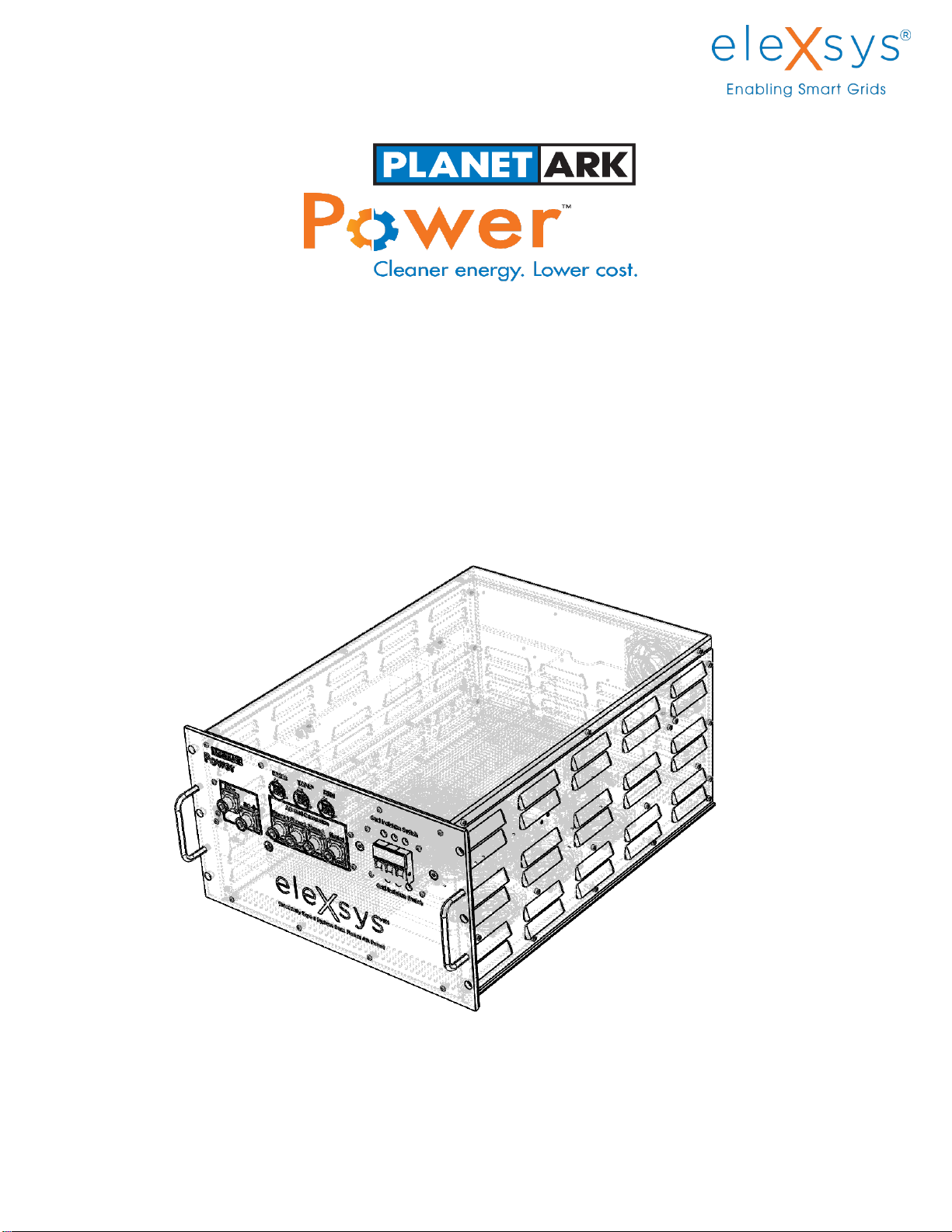
Figure 2:eleXsys product appearance..........................................................................................................................15
Figure 3: An illustration of EEdS30 architecture..........................................................................................................21
Figure 4: Electrical connection diagram between the battery and main AC grid .......................................................22
Figure 5: Installation procedures.................................................................................................................................24
Figure 6: eleXsys rack mounting bolts ......................................................................................................................... 25
Figure 7: Illustration of mounting clearance (in mm) and ventilation requirement (arrows indicate air-flow direction)
.....................................................................................................................................................................................26
Figure 8: EEdS front panel connection layout .............................................................................................................28
Figure 9: Amphenol Surlock connectors......................................................................................................................29
Figure 10: AC and DC terminal safety cover................................................................................................................30
Figure 11: Circuit breaker safety cover........................................................................................................................31
Figure 12: Earth post components ..............................................................................................................................32
Figure 13: RJ45 Connector...........................................................................................................................................33
Figure 14. Demand response mode.............................................................................................................................38
Figure 15. Power quality response mode....................................................................................................................39
Figure 16. Characteristic curve of EEdS power exporting to grid under Volt-Watt mode..........................................40
Figure 17. Characteristic curve of EEdS power importing from grid under Volt-Watt mode .....................................40
Figure 18. Characteristic curve of EEdS under Volt-Var mode....................................................................................41
Figure 19. Characteristic curve under fixed reactive power mode .............................................................................42
Figure 20. Batter operating mode flow chart..............................................................................................................44
Figure 21: GUI labelled home page .............................................................................................................................48
Figure 22: Setup Tab ....................................................................................................................................................48
Figure 23. Software GUI under debugging mode........................................................................................................50
Figure 24. Front panel..................................................................................................................................................54
Figure 25. Side panel....................................................................................................................................................54
Figure 26. Back panel...................................................................................................................................................55
Figure 27. Demonstration of battery charging at >= 99 % Status of Charge (SOC).....................................................56
Figure 28. Demonstration of fixed power factor mode at PF = 0.8.............................................................................57
Figure 29. Demonstration of over-voltage protection ................................................................................................58
Figure 30. Demonstration of under-frequency protection .........................................................................................58

Commercial-In-Confidence Page 5 of 58 © eleXsys R&D Pty Ltd Apr 2020
List of Tables
Table 1: EEdS30 Technical Specifications ....................................................................................................................14
Table 2: Minimum recommended specifications to install an eleXsysTM EEds 30 ......................................................22
Table 3: Environmental parameters............................................................................................................................25
Table 4: EEdS installation specification .......................................................................................................................27
Table 5: Nuts, bolts and tightening torque..................................................................................................................27
Table 6: List of connection ports .................................................................................................................................28
Table 7: RJ45 Cat5 pinout diagram..............................................................................................................................33
Table 8: DRED RJ45 socket assignment .......................................................................................................................33
Table 9: EEdS commissioning tests..............................................................................................................................35
Table 10: Battery commissioning tests........................................................................................................................35
Table 11: Operation modes .........................................................................................................................................49
Table 12: Modbus Register Map..................................................................................................................................51
Table 13. Parameters configure for battery charging and discharging.......................................................................56

Commercial-In-Confidence Page 6 of 58 © eleXsys R&D Pty Ltd Apr 2020
SYMBOLS
Symbol
Description
Consult user documentation
WARNING: RISK OF DANGER.
WARNING: HAZARDOUS VOLTAGE /
RISK OF ELECTRIC SHOCK
Earth
Battery
NOTE: Refer to manual as improper
usage may damage the equipment
The affixed label directs that this
electrical/electronic device must not
be discarded in domestic household
waste.

Commercial-In-Confidence Page 7 of 58 © eleXsys R&D Pty Ltd Apr 2020
1. Product Information
1.1. Scope
This document has been compiled to assist with the installation and operation of the eleXsys Energy dSTATCOM
(EEdS) Model EEdS30. The EEdS can be used for many applications such as:
1. An electronic inductor/capacitor for VAR management;
2. Power conditioner to stabilise the power at a connection point;
3. A battery charger/discharger for energy storage;
4. A harmonic sink to remove selected harmonics from a power supply;
5. An uninterruptable power supply;
6. An off grid power supply;
7. Three-phase supply phase balancing.
The EEdS is usually used in conjunction with the eleXsys Energy Management System (EEMS) which integrates the
EEdS with other associated equipment to perform many of these applications.

Commercial-In-Confidence Page 8 of 58 © eleXsys R&D Pty Ltd Apr 2020
1.2. Model
EEdSxxyy where xx indicates the nominal rating of the eleXsys dSTATCOM, and yy indicates the manufacturing batch.
1.1.1. Tag Information
A device information tag/nameplate is attached to the eleXsys, as seen in Figure 1, with all relevant information
about the device included. The information is model specific this tag will include the model of the device as well as
a serial number, identifiable by eleXsys Energy, and a date of manufacture.
Model:
EEdS 3042
Serial No.:
EES30-1118-1001
Date of
manufacture:
09-2019
eleXsys R&D,
160 Samford Rd,
Brisbane, Australia
DC Energy
Storage
AC
3P + N + PE
VDC range
VDC nom
VDC max
IDC nom
IDC max
650 - 1000
800
1000
38
60
VAC nom
Snom
fAC
IAC nom
Icc
V
VA
Hz
A
A
400
30000
50/60
44
60
V
V
V
A
A
Inverter topology
Protective class
Over voltage category
Mass max
Temperature range
Humidity range
IP Rating
Lithium-Ion
0 - 1 - 0
Leading and Lagging
Non-isolated
Class I
AC: III, DC: II
35kg
0°C ~ +60°C
5% ~ 85%
IP31
TP07
Storage Type
Power Factor
Figure 1: Device nameplate example

Commercial-In-Confidence Page 9 of 58 © eleXsys R&D Pty Ltd Apr 2020
1.3. Features
The EEdS is an advanced four-quadrant, three-phase, 4 wire 30 kVA inverter which uses the latest Silicone Carbide
and polypropylene capacitor technology to give an expected life of 20 years. The EEdS inverter has the following
features:
True three-phase 400VAC 30kVA inverter in one package;
Can be operated as a three-phase four-wire @30kVA or single two-wire @20kVA;
Frequency 50 or 60Hz;
DC input range 600 - 1000VDC;
Full four-quadrant - capable of sourcing/sinking VARs and import/exporting kW to full rating;
Four wire three-phase with individual phase current balancing;
Battery charging and discharging of energy storage devices;
Power conditioning compensation for grid sag/swell and voltage fluctuations;
Programmable harmonic sink;
Selectable current source or voltage source inverter;
Power factor correction;
Power flow regulation;
Uninterruptable Power Supply (UPS) function;
Off grid operation;
Communication Interface - TCP/IP or WIFI;
Communication Protocol –Modbus;
Data logging for one year.
1.3.1. Three-phase or single-phase
Two versions of the EEdS are available. A three-phase four wire @ 30kVA unit or as a single-phase two wire 240VAC
@ 20kVA unit. The EEdS is factory configured for each of these configurations. Both units are transformer-less
operation.
1.3.2. DC voltage range
The DC voltage range of the EEdS is 600 - 1000VDC. For three-phase operation the DC voltage range is typically 680-
980VDC depending on the AC output voltage required.
1.3.3. Frequency
Frequency can be configured for either 50Hz or 60Hz.

Commercial-In-Confidence Page 10 of 58 © eleXsys R&D Pty Ltd Apr 2020
1.3.4. Four quadrant operation
The EEdS is capable of
1. Import real power up to 30kW;
2. Export real power up to 30kW;
3. Generate VARs up to 30kVAR (capacitive);
4. Sink VARs up to 30kVAR (inductive).
1.3.5. Phase balancing
The EEdS is essentially a four-phase device with the neutral being modulated to measure and remove any negative
phase sequence components resulting in a balanced three-phase current output. For an unbalance situation, phase
currents can be balanced by generating currents between phases to balance the phase currents. Phase balancing is
optional.
1.3.6. Battery charging and discharging
The EEdS is capable of discharging a connect battery up to its full rating of 30kVA at any power factor between zero
and one. It has built in constant current/ constant voltage algorithm for charging various lithium batteries. The
charging current, charging voltage and cut off voltage can be set for different battery chemistries.
1.3.7. Power conditioning
The EEdS can be used as a power conditioner to improve the quality of supply. It is capable of regulating the phase
voltages to particular voltage and bandwidth. The voltage and hysteresis bandwidth are user settable. Sags and
swells will be corrected by first sourcing or sinking VARs to the correct voltage exertion and, if a battery is present,
will correct the voltage by generating or consuming real power. Sag and swell thresholds (voltage and time) for
correction are also user settable.
1.3.8. Harmonic correction
The EEdS is capable of sinking selected harmonics to improve total harmonic distortion of voltage supply. The unit
can be programmed to present a low impedance to neutral for programmed frequencies.
1.3.9. Current or voltage source inverter
The EEdS can be programmed as either a voltage source EEdS for off grid applications or a current source EEdS for
on grid applications.
1.3.10. Power factor correction
The EEdS can be used as a continuously dynamic power factor correction device to maintain unity power factor for
an installation. The generation of VARs for power factor correction is continuous not stepped as in standard power
factor correct products that use capacitors.

Commercial-In-Confidence Page 11 of 58 © eleXsys R&D Pty Ltd Apr 2020
1.3.11. Power flow regulation
The EEdS can be used to regulate power supplied to a connected load (i.e. demand limiting).
1.3.12. Uninterruptable Power Supply (UPS) –future development
EleXsys may be utilised as a line interactive uninterruptable power supply (UPS). For example, if the main grid supply
is lost, the eleXsys EEdS with a battery bank will maintain supply to the connected load by changing its operation
from current mode to voltage mode within one 50 Hz cycle, and provide kW and kVARs to all loads.
1.3.13. Off grid operation –future development
The EEdS may be used for off grid applications usually in conjunction with a battery and configured as a voltage
source inverter.
1.3.14. Grid Voltage Regulation
The EEdS can be used to regulate the voltage at a customer’s connection to the grid. By either sourcing or sinking
VARs, the voltage at the point of common coupling can be controlled to a specified voltage range. In this mode, the
EEdS can be used to limit voltage rise for DER generation and for improving voltage drop under high load conditions.

Commercial-In-Confidence Page 12 of 58 © eleXsys R&D Pty Ltd Apr 2020
1.4. Communication and Data Logging
The EEdS consists of two RJ45 connection ports for software communication, DRED control and data logging
functionality. The USB port is used for hardware developing purpose, and it will not be provided in the
commercialized version. WIFI communication functionality is pending upon the next stage hardware development.
1.4.1. Communication Interfaces
1. RJ45;
2. WIFI (optional);
3. USB port (optional).
1.4.2. Communication protocols
1. TCP/IP;
2. TCP/IP Modbus;
3. DNP3.
1.4.3. Data logging
The EEdS has non-volatile memory to store logged data and parameters for seven days internally. When used with
the EEMS, any logged data is transferred each 30 minutes to a local SQL database and master database on a remote
central server.

Commercial-In-Confidence Page 13 of 58 © eleXsys R&D Pty Ltd Apr 2020
1.5. EEdS30 Specification
The function and the rating of the EEdS30 have been summarized in the following table. For detailed specifications,
please refer to Table 1.
Topology three-phase transformer-less. Four-arm bridge topology, the fourth arm is located on
the neutral and facilitates phase voltage balancing.
1
Single-phase operation may be
achieved by firmware changes and by terminal re-configuration.
Voltage 400VAC three-phase (Parameters)
Nominal frequency 50/60 Hz
Power 30 kVA four-quadrant bi-directional source or sink real power and VARs
Peak power ±30kVA with ambient temperature of 40˚C
±45 kVA for short term (capped by the operating temperature, future version)
DC Input voltage range 600 –1000VDC
Overload control Current control –short circuit response defined by firmware
PWM switching 48 kHz
Output waveform Sinusoidal < 2.5% THD
Switching technology Silicon Carbide MOSFET
DC bus capacitor Polypropylene
2
Firmware platform Dual Delfino™ 32 bit processors
Firmware security Encrypted to AS 256
Communications interface Ethernet
Protocols Modbus TCP/IP, DNP3
Standards AS4777.2
AS62040.1.1; AS60950.1
IEC62116
AS 61000.6.3; AS61000.6.4
Physical 485mm Wide X 277mm High X 602mm long (6.3U Rack Unit mounting)
Cooling Fan forced
1
Note that the fourth arm makes it possible to connect a single 3phase inverter as a single or “two phase” inverter (“Two phase” is useful in Single Wire
Earth Return systems (SWER) and in US split transformer systems).
2
Product does not use Electrolytic capacitors at any level - neither Aluminium nor Tantalum
All capacitors are either polypropylene or ceramic. The Capacitors used on the dc bus have a design life of 30 + years

Commercial-In-Confidence Page 14 of 58 © eleXsys R&D Pty Ltd Apr 2020
Table 1: EEdS30 Technical Specifications
Model: EEdS 3042
DC PORT - ENERGY STORAGE
DC voltage range
650 ~ 1000V
DC MAX current
60A
DC MAX power
30kW
AC OUTPUT RATINGS - GRID TIE PARAMETERS
AC rated voltage
400V
*Software configurable
AC voltage range
184 ~ 264.5V
*Software configurable
AC rated current
44A
*Software configurable
Rated frequency
50Hz
*Software configurable
Frequency range
45 ~ 55Hz
*Software configurable
AC rated apparent power
30kVA
*Software configurable
Power factor range
0 leading ~ 0 lagging
*Software configurable
Output THD
<2.5%
SYSTEM PARAMETERS
Wiring mode
3P4W+PE
AC breaker rating
63A
Isolation mode
Non-isolating
Protective class
Class I
Over voltage category
AC: III, DC: II
Active anti-islanding method
Regular disturbance method
Active trip
10us min, 20us nom, 40us max
Fast protection in extreme conditions
Passive trip
1 ~ 2s
According to AS4777
Cooling
Internal fan-forced cooling
Noise
<60dB
Working temperature range
0 ~ 40˚C
Temperature derating (Ta)
N/A
IP degree
IP31
MAX elevation
2000m (derating from 2000m)
Weight
35Kg
Size (W*D*H)
485*602*277mm
Battery type
Lithium-ion only
Communication protocols
Modbus TCP/IP, TCP/IP, DN3P
Communication socket
RJ45, RS232
WARNING!
The EEdS30 comes from the factory with the country code pre-set. To update the country
code please contact the manufacturer.

Commercial-In-Confidence Page 15 of 58 © eleXsys R&D Pty Ltd Apr 2020
1.6. Appearance
The eleXsys is a rack mounted inverter with the grid, battery, and communication connections mounted on the front
panel for easy installation. The device has two handles at the front for easy installation and removal, see Figure 2.
The dimensions of the unit are included in the diagram below with an additional 40mm added to the length if the
handles need to be taken into account.
Figure 2:eleXsys product appearance
WARNING!
The EEdS30 weighs 37kg and requires two persons to manually install or move at any time. It
is not recommended for a one person lift or manual handling.

Commercial-In-Confidence Page 16 of 58 © eleXsys R&D Pty Ltd Apr 2020
2. Installation Guide
2.1. Applicable Standards and Guides
A list of standard and guides which provide relevant guidance on high voltage and fire safety issues related to
installation includes, but is not limited, to the following publications:
Australian/New Zealand Standard AS/NZS 3000:2018 Wiring Rules Section 7.8.8.
AS 4777.2:2015 Grid connection of energy systems via inverters Inverter requirements
IEC 62116:2014 Utility-interconnected photovoltaic inverters - Test procedure of islanding prevention
measures
AS 61000.6.3:2012 Electromagnetic compatibility (EMC) Generic standards - Emission standard for
residential, commercial and light-industrial environments
AS 61000.6.4:2003 Generic standards –Emission standard for industrial environments
AS 62040.1:2019 Uninterruptible power system (UPS) –Part 1: Safety requirements (IEC 62040-1:2017
(ED2.0), MOD)
AS 60950.1:2015 Information technology equipment - Safety Part 1: General requirements (IEC 60950-1,
Ed. 2.2 (2013), MOD)

Commercial-In-Confidence Page 17 of 58 © eleXsys R&D Pty Ltd Apr 2020
2.2. Pre-cautions
2.2.1. Potential Hazards or Injuries
Electric Shock
The human body responds in several ways to electrical current flowing through it. The sensation of shock is
only one such effect and this can be extremely painful. When a shock is received, the electric current may take
multiple paths through the body and its intensity at any one point is difficult or impossible to predict. The
passage of the electric current may cause muscular contractions, respiratory failure, and fibrillation of the
heart, cardiac arrest or injury from internal burns. Any of these can be fatal.
Electrical Burns
Electric burns are due to the heating effect caused by the passage of an electrical current through body tissues.
They are most commonly associated with an electrical shock and often occur in and on the skin layers at the
point of contact with the electrical conductors which give rise to the electric shock.
Fires of an Electrical Origin
Electric Fires are caused by the heating effect of conductors passing current either intentionally or through
fault conditions such as when fault current flows, poor connections resulting in heat generation and possibly
Thermal ‘Run away’. Likewise, fires may result from arcing or explosions; igniting local fuel sources.
Electric Arcing
Arcing may result from intended or unintentional operations or activities. Arcing may result when an electrical
fault between live conductors or between live conductors and earth develops, when switching operations break
a high current circuit or when overcurrent devices attempt to clear a fault current. Arcing occurs when the air
acting as an insulator becomes ionised and becomes an electrically conducting agent, thus allowing current
flow to continue.
Explosion of Electrical Origin
Where as a result of any of the conditions detailed above caused local mediums to explode, or where the
electrical system explodes due to fault current or arcing.
2.2.2. Risks and Safety
Use of accessories not recommended or sold by eleXsys Energy Pty Ltd may result in a risk of fire, electric
shock or injury to person;
The EEdS is designed to be connected permanently to your AC or DC electrical systems. All wiring should be
installed by a licenced electrician or qualified technician. This will ensure the installation is adhering to the
local and the national electrical standards applied in your application;
Do not operate the EEdS with damaged or substandard wiring to avoid a risk of fire and electrical shocks;
Charge only with the rechargeable type batteries. The EEdS needs to be configured prior the use of new
installed batteries;
Do not operate the EEdS if it has received a sharp blow, been dropped or otherwise damaged in any way.

Commercial-In-Confidence Page 18 of 58 © eleXsys R&D Pty Ltd Apr 2020
Do not self-service or disassemble the EEdS. This should only be conducted by authorised and qualified
technician or electrician;
Do not expose the EEdS to extreme weather conditions. The EEdS shall not be used as an outdoor device and
a cabinet with an IP rating greater than IP55 is required;
Before any maintenance work is carried out, all sources of AC and DC power should be disconnected. Also,
10 minutes wait time should be given after the disconnection before conducting any further action. The
internal capacitor requires at least three minutes to be fully discharged depending on the voltage level;
The EEdS enclosure shall be connected to the MEN system with a 6mm2earth wire.
2.2.3. Working with Batteries
The EEdS has a DC rating of 1000VDC. All DC wiring shall a voltage rating greater than 1000VDC. All fuses,
circuit breakers, bus bars, terminals and connectors shall have a rating of at least 1000VDC;
Any DC equipment connected to the battery shall have a fault rating greater than the prospective fault rating
of the battery;
Any battery connected to the EEdS shall not be earthed;
Once the connection between battery and EEdS is made, the battery types, size, preferred operating
characteristics should be configured in the EEdS firmware;
If high voltage battery bank is connected, the area should be restricted to people whom has the authority or
knowledge about high voltage applications;
A dry chemical type extinguisher should be nearby in case of any fire accident.
2.2.4. Labelling of Electrical Apparatus
All operable electrical apparatus, underground cables, power transformers and voltage regulators should be
clearly and permanently labelled with a unique identifier except:
High voltage dropout fuses protecting a labelled pole mounted transformer substation or a labelled ground
mounted transformer substation with the fuse pole immediately adjacent to it; or OPERATIONAL
PROCEDURE –Electrical Safety Rules
Switch gear associated with labelled recloser, regulator and sectionaliser sites which are mounted on
common structures; or
Low voltage fuses or links associated with and on the same structure as a labelled pole mounted or ground
mounted transformer substation; or
Any other clearly identified operational apparatus such as low voltage service fuses, temporary mid span
high voltage live line links and live line clamps.
WARNING!
Do not connect or disconnect the battery while the EEdS is operating. Disconnecting the DC
leads while the battery is operating will result in severe arcing and injury to personnel.

Commercial-In-Confidence Page 19 of 58 © eleXsys R&D Pty Ltd Apr 2020
Danger Tagging
“Danger - do not operate”tags must be attached to the controls of operable electrical apparatus to warn persons
against inadvertent or unauthorised operation (that would endanger the safety of persons or the reliability and
quality of supply) unless attachment to the controls is impractical in which case danger tags must be attached in the
next best locations to effect the warning.
“Danger - do not operate”tags must only be installed, altered or removed by authorised persons.
“Danger - do not operate”tags must also be fitted to unserviceable equipment to warn against inadvertent
energisation.
Persons shall not remove or alter in any way any tags that have been applied, without consulting the Network
Operator or person who attached the tag.
WARNING!
When an alteration occurs to electrical apparatus requiring labelling, the labelling must be
immediately altered to reflect the changed arrangement and system diagrams must also be
updated concurrently.
Table of contents
Popular Power Inductor manuals by other brands

Delta Electronics
Delta Electronics SIG3010 Specification sheet

Delta Electronics
Delta Electronics SMT Power Inductor SIL720 Specification sheet

Delta Electronics
Delta Electronics MPL10X Specifications

Delta Electronics
Delta Electronics SMT Power Inductor SIL520 Specification sheet

Delta Electronics
Delta Electronics SI415 Specification sheet

Delta Electronics
Delta Electronics SMT Power Inductor HMP1352 Specifications