ElfinX TX-DSR16 User manual

http://www.elfinx.com 1
DigiNet User Manual
Server and Client
Model#: TX-DSR16
OWNER’S MANUAL
CONTENTS:
OPERATING INSTRUCTIONS
DESCRIPTION OF FUNCTIONS AND FEATURES
INSTALLATION GUIDE
Before proceeding, please read this manual thoroughly!

http://www.elfinx.com 2
1.0 Installation:
Main Card:
Top 16 Pins are positive connection
and connect as picture on left
(white/red wires).
Lower 16 Pins are ground connection
(gray wires)
Extend Cards:
Lower 4 Pins are positive connection and
connect as picture on right (white/red wires).
Top 4 Pins are ground connection (gray wires)

http://www.elfinx.com 3
2.0 Main Screen or Default Screen:
1. Time and Date – Displays current time and date.
2. Search – Displays search menu which includes playback, search, and/or save file for backup by it’s date,
time, and camera.
3. Setup – Displays setup menu which includes settings for hardware, motion, passwords, screen division,
modem, system setup, and site information.
4. Storage – Percentage of space remaining on current drive.
5. Quit – Exiting the DigiNet software.
6. Camera – Click the desired numbered button to view the camera you want displayed on the screen.
7. Screen Division – Select the divisions of cameras on the displayed screen.

http://www.elfinx.com 4
Hardware Setup
1. Camera Setup – Settings for each camera.
•[Setup] – Checkmark to include (enable or disable) camera.
•[Name] – Assign a name to each camera.
•[Sensor] – Enter a sensor number that will trigger the camera to record if set off.
•[Motion] - Enter the camera number(s) to be associated to the camera that detects motion. When
detected, the appropriate cameras will be recorded.
•[P/T] – Checkmark if camera is Pan/Tilt/Zoom.
•[Type] – Select the make of the PTZ camera (only available if P/T is checked).
2. External Monitor – If external monitor is being used, checkmark the cameras that are to be displayed on
that monitor. Cameras are displayed in sequence.
•[Select Time (sec)] – Enter the interval (in seconds) between each camera displayed.

http://www.elfinx.com 5
3.1 Setting Up Sensors/Controls:
3. Sensor Setup (Applicable only if sensors are available and is being used)
•[Setup] – Check mark to activate sensor.
•[NC/NO] – Click button to select type of sensor connection (NC - Normally Closed, NO - Normally
Open).
•[Auto ON/OFF Time] – Designated time when the sensor is active (default is continuous 00:00-24:00). If
sensor is triggered outside the specified time, it will be ignored.
•[Use Alarm/Do not use alarm] - Select either option to activate an alarm when the sensor is tripped
•[Recording time by sensor motion] - The time to begin recording after a sensor detects motion
4. Control Setup (Applicable only if controls are available and is being used)
•[Setup] – Checkmark to activate and use specified control.
•[Name] – Assign a name to each control.
•[Auto ON/OFF Time] – Designated time when the control is active (default is continuous 00:00-24:00). If
sensor is triggered outside the specified time, it will be ignored.
•[Sensor] – Specify which sensor is associated with the control (use commas to separate more than one
sensor).
•[Working sec] – Enter the length of time (in seconds) that the control is turned on, when activated by
sensor(s) or manually on the display screen mode.
Note: For information on connecting sensors/controls refer to Technician Training Manual (Section 10.83
Connecting Sensors/Controls)

http://www.elfinx.com 6
4.0 Motion Setup:
1. Camera: Click on a numbered button to define motion settings for a selected camera.
2. Target Zone: Define up to five detection zones per camera for triggering motion recording.
3. Individual Camera Motion Setting:
•Sensitivity: Adjust the sensitivity in the detection zone by using the scroll arrow.
•Alarm:
•Area Clear: Will clear all detection zones for a selected camera.
•Area Draw: Will draw a detection zone covering the whole area for a selected camera.
•Brightness / Hue / Contrast: Adjust the brightness, hue and contrast of each selected camera.
•Color:
•Default: Return to the default settings.
4. Recording Frame rate per Camera (sec): Each camera’s recording rate is adjustable.
Default: The default setting is as followed [4 chan – 30 fps / camera ~ 8 chan – 30 fps / camera ~ 16
chan – 8 fps / camera].
*If you increase the speed of a certain camera, the speed of the other cameras will be decreased with 8 & 16
chan.
5. Setup for all Cameras:
•Area Clear: Will clear all detection zones for all cameras.
•Area Draw: Will draw a detection zone covering the entire area for all cameras.
•Screen size: Set screen size from 160x120 to 320x240, and 640 to 480.
•Quality: Set screen quality from best, high, normal, low and lowest.
•Transfer Quality: Set the quality of the image transferred to either best, high, normal, low or lowest.
•Color of Motion Area: Select the color of motion detection area in the display mode between green or red.
•Full Screen When Motion: Select from multi to full screen when activity is detected.
•Set Quad Rotation Time:

http://www.elfinx.com 7
5.0 Schedule Setup:
1. Camera: Click on a numbered button to define motion settings for a selected camera.
2. Calendar: To set the recording settings (in simple mode Weekend, Saturday’s, and Sunday’s/ Holidays;
the time [hours] settings will be the same.)
a. Camera: Click on the desired camera to set to recording settings.
b. Weekday: Set the recording mode for the weekday (C-continuous, S-sensor, M-motion, P-
Prealarm).
c. Saturday: Set the recording mode for Saturday (C-continuous, S-sensor, M-motion, P- Pre-alarm).
d. Sunday/Holiday: Set the recording for Sunday and for holiday(s).
3. Advance Mode: Switch to Advance Mode.
4. Record Mode:
•Continuous: Check to continuous recording (note: If this function is selected then all other recording
settings will be canceled).
•Sensor: Check to have sensor active recording.
•Motion: Check to have motion active recording.
•Pre-Alarm:
5. Copy To: Click here to copy recording setting to one or to all of the other cameras.

http://www.elfinx.com 8
6.0 Screen Division Setup:
1. Screen Divisions: Choose the screen / split division (this allows you to hide any camera).
2. Camera Selection: Select camera to be placed on the screen division.
3. Large Screen: You can select the larger screens for magnification among the 6, 10, 13 divisions.
4. Default: Initialize into default

http://www.elfinx.com 9
7.0 Modem Steup:
1. Type of Connection: LAN, PSTN, ISDN, Leased Circuit can be used for remote connection. ISDN or
Leased circuit with router connection is possible and; ISDN or PSTN can be used to connect to a DVR
without router directly. If you don’t use remote connection check on “No Connection”
2. Password / Confirm: Enter a 4 number password to log into the site from center the P.C.
[password] : enter the 4 number password.
[confirm] : re-enter the password to confirm.
3. Emergency Info:
a) Sensor for Emergency: If the sensor detects any signal it will send an alarm to the center with the
captured image during the designated time.(You can assign the external sensor numbers.)
b) Emergency Phone Number: When you use PSTN for connection you can assign up to 2 phone
numbers for an emergency connection. When the first trial fails to connect, it tries to connect to
the second number.
c) Transfer Time: When connection has been made, you can assign the time in seconds to transfer
the image to the Center PC. (If any other signal is detected during the transfer, the DVR will
transmit the image again.)
d) Emergency IP Address: Enter the IP address on “Emergency IP Address” to connect to a
designated site. (Under LAN, Leased Circuit connection)
http://www.elfinx.com 10
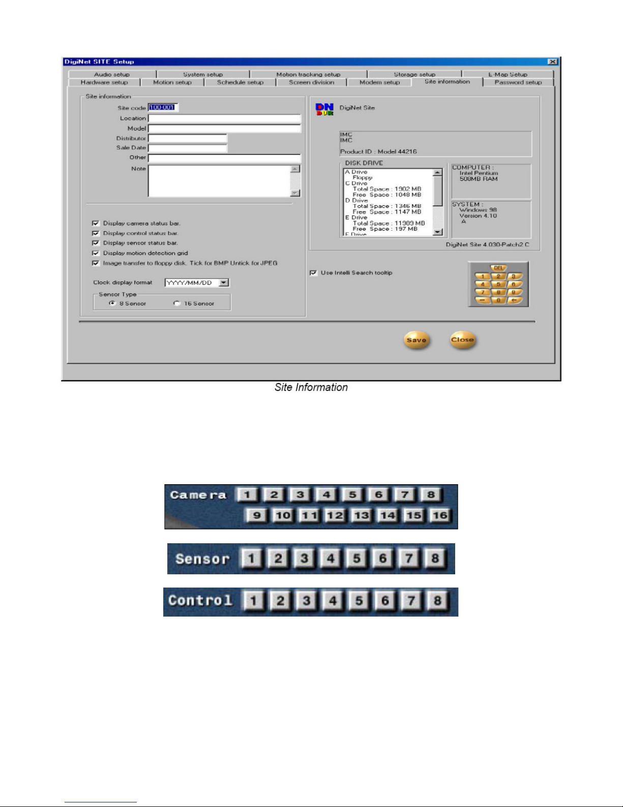
8.0 Site Information:
1. Site Information: Enter the site code, location, model, version, distributor, and the purchase date. It is
important that you enter the site code and to also remember it’s code for remote viewing (When you try
to connect to the site from a remote location, the system will check the site code and password together. If
either the code or the password is incorrect then you will be disconnected from the site.
2. Display Camera Status Bar: This bar displays the main screen if selected.
3. Display Control Status Bar: This bar displays occurrence of sensor signal.
4. Display Sensor Status Bar: This bar displays the current status of control in surveillance mode. (On or Off)
5. Display Motion Detection Grid: This displays the “on” or “off” condition of the detection under the
motion detection mode.
6. Image Transfer to Floppy Disk: If you select this function, it stores the data in JPEG onto a floppy disk. If
you don’t select this function, it stores the data in BMP format.
7. Clock Display Format: It is a format of displaying the time. Select the type of display you want.
8. Sensor Type: Select ‘8 SENSOR’ to use 8 Sensors, and ’16 SENSOR’ to use 16 Sensors. Proper number of
Sensor buttons will be displayed in the surveillance mode when you chose ‘Sensor Type'. You’ll be able to
see the proper number of buttons in ‘Hardware Setup’ and ‘Communication Setup’.

http://www.elfinx.com 11
9.0 Password Setup:
1. Setup List: Check the setup that can be modified by operator 2 and operator 3. (Operator 1 has control
over all setup.)
2. Password Change: You can assign a password to three users with different functions. Only user 1 can
modify all the setup.
a) Enter the password you are presently using.
b) Enter the new password.
c) Confirm the new password.
**Password is set with only 4 numbers**
**Password is not set in the initial status**
3. Advanced Security Setup: Allows User 1 to change the cameras that are enabled and whether or not the
search mode is enabled.
After selecting Advanced Security Setup the following dialog will appear:
Input the User1 password and
select OK in order to continue.
When the window to the left appears, check the
appropriate checkbox according to the desired option.

http://www.elfinx.com 12
10.0 Audio Setup:
1. Audio Settings
a) Audio Save Enable: After selecting the camera to record the sound, click on the ‘audio enable’.
The sound data, via microphone, will be recorded together with the video data. The sound data
will be recorded when the video signal starts recording. The sound data will not be recorded if the
video data is not being recorded at the same time. Sound cards should be installed in order to
record sound data.
(Audio Save Enable will be “checked” off automatically when your system doesn’t have a sound
card.)
b) Audio Playback Enable: After selecting the camera to played, click on ‘Audio Play Enable’ The
sound will be played with the video signal on.
2. Camera: Select the camera number to save and play the sound. Currently, sound data can be recorded
only on one channel. You can choose the desired camera to record the sound.

http://www.elfinx.com 13
11.0 System Setup:
1. System Off Line: Assign the specific time to turn off by clicking on the desired date and time.
2. Watermark
a) How to Use Watermark: You can authenticate a Watermark onto an image. This action becomes
active when you click the Watermark function.
b) Display Watermark protect image: This will or will not display the “Watermark" onto an image.
If you click on this option, the image will have a Watermark authentication image.
3. Hardware Setup
a) VGA: Select the type of VGA. Proper VGA is set in the factory
b) Control Card Port: Select Com port of Control card. Correct port is selected in the factory.
c) Video Format: Choose between NTSC and PAL.
4. System Restart Time: This sets the time to reboot the system daily and automatically. To activate this,
click on [Use].
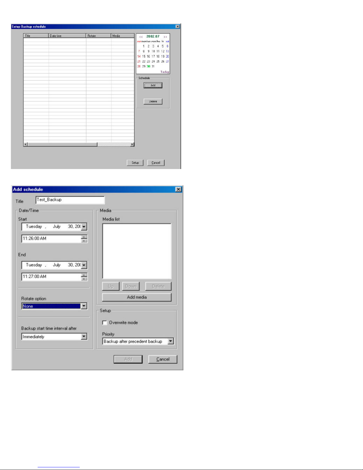
5. Backup
Backup Settings: Is used to set a schedule for running backups.
http://www.elfinx.com 14
11.1 Setting a Local or Remote Backup:
After selecting the Backup
settings button, the window to
the left will appear.
a)
b)
c)
d)
e)
f)
g)
Enter the title of the backup into the Title
text box.
Set the Start date & time from the Start
section.
Set the end date & time from the End
section.
In the Rotate Option, pull down the select
key.
The Backup Start Time Interval After
suggests whether or not you would like to
begin immediately or to begin at a later
time. You can choose either option.
Set the Priority of the backup file by
selecting an option from the Priority pull
down menu.
Select Add Media to add the type of
backup.

http://www.elfinx.com 15
h)
i)
j)
k)
l)
Select local drive/remote drive for the
desired media.
To backup to a local drive select the Local
drive option. Then select the drive letter
from the Path pull down menu.
j) To backup to a remote drive, select the
Remote Drive option.
k) Enter the IP Address of the remote PC in
the IP Address text box. Then enter the
password to access the drive in the
Password text box.
l) Select the appropriate remote drive by
clicking the Select Drive button
m) Select OK, then Add in the Add Schedule window when it appears. Review the scheduled backup, then
select Setup to confirm the Backup Settings.

http://www.elfinx.com 16
12.0 Motion Tracking Setup:
1. Enable Camera
a) Current Camera: You can activate the Motion Tracking function when you have a proper speed
dome camera. In order to setup in detail, you need to select a specific camera to track the motion.
2. Start Position: This configures the starting point of the camera. Pan and Tilt the position of your camera
for the starting point.
a) Screen Value: You can get the rectangular value of the current position of the camera by clicking
this button.
b) Move Camera: This button moves the camera to the configured position.
c) Return Start Position: The dome camera goes back to the starting point in seconds when it stops to
rack a moving object.
3. Range:
a) Pan: You can assign the angle to move left and right. The camera moves from the ‘start position’
that you set in ‘Start Position’. The maximum value to the left and right is 40 degrees. The sum of
value to the left and to the right cannot exceed 360 degrees. If the sum of both the values exceeds
360 degrees, then value will be adjusted automatically.
b) Screen Value (Pan): You can get the current camera position by clicking this button.
c) Enable (Pan): If you click this box, the camera will move within the value of the angle
d) Tilt: You can assign the minimum angle in Tilt based on the value you put in the ‘Start Position’.
e) Screen Value (Tilt): You can get the current minimum value of theTtilt by clicking this button
f) Enable (Tilt): If you click this box, the camera will move within the value of the angle
4. On/Off Time: You can select the time to activate the Motion Tracking function. The default value is
00:00 ~ 24:00 (continue for 24 hours). The camera works in Pan/Tilt mode outside of the configured time.
a) Disable PTZ mode: Disables PTZ mode from the Motion Tracking camera. If you don’t select this
option, both Motion Tracking and PTZ will be used.
5. Set Value:
a) Pan Angle: Adjust this value when the selection box is outside of the position in left and right.
b) Tilt Angle: Adjust this value when the selection box is higher or lower than the position chosen.
c) Sensitivity: If you increase or decrease this value, the camera movement will be more or less
sensitive. You need to adjust this value properly depending on the location. Also the Motion
Tracking may become sensitive to light and may move a little.
d) Camera Flip: Use this function when the dome camera is flipped. When the dome camera is installed in
flip position, it will work in reverse. In this case , the dome camera may appear broken. This function
therefore should be used to prevent something like this from happening.

http://www.elfinx.com 17
13.0 Storage Setup:
1. Scroll Allocation Menu: Displays the Hard Drive that is allocated. Data regarding possible disk space and
allocation status for each drive will be shown.
a) Click on Modify Storage Structure. This will take you to “Storage Structure”.
b) Close DigiNet Site Setup.
14.0 Storage Setup (continued):
2. Modifying Storage Structure: Allocation for each drive can be changed.
a) Allocation: Click on the desired drive to be allocated. (Note that Drive C cannot be reformatted
since it holds the operating system).
b) Proceed: Click to continue once the proper drives are selected for re-allocation.
c) Cancel: Click here to cancel.

http://www.elfinx.com 18
E-Map Setup:
1. How to use E-map: Select this to activate the E-map on the main Screen.
2. Position No: Choose the desired position number.
3. se Image copy (or change): Click the Find button to select a bitmap to load as the E-Map
4. Setting: Can e used to set the positions of cameras, controls, and/or sensors
a) Camera: Select the camera, then click the desired position for the camera on the E-Map
b) Control: Select the control, then click the desired position for the control on the E-Map.
c) Sensor: Select the sensor, then click the desired position for the sensor on the E-Map..
In the Setting section, select the type of Camera, Sensor or Control from the pull down menu
Note: To save the E-Map design, select the Save button at the bottom right.

http://www.elfinx.com 19
16.0 Intelligent Search Mode:
To activate Intelligent Search mode, go to setup and click on the “Site Information” tab and put a check mark
on the “Use Intelli Search Tool Tip”.

http://www.elfinx.com 20
Once you are in the Intelligent Search Mode the following screen will appear:
To Search by Date and Time:
By clicking on the following options, you can search one or more cameras:
Table of contents
Popular Software manuals by other brands

ZyXEL Communications
ZyXEL Communications VANTAGE REPORT - manual

HP
HP ProLiant StorageWorks NAS 2000s quick start guide

F-SECURE
F-SECURE PSB Getting started guide

Canon
Canon VIXIA HF M30 instruction manual

Waves
Waves Dynamics Processor MV360 user manual

Novell
Novell LINUX ENTERPRISE SERVER 10 SP1 - ARCHITECTURE-SPECIFIC INFORMATION... supplementary guide


HP
HP t5565 - Thin Client Administrator's guide

Brother
Brother BES Monogramming Suite instruction manual

Novell
Novell ENHANCED SMART CARD METHOD 3.0.1 - INSTALLATION... installation guide

Inalp Networks
Inalp Networks SmartWare R2.00 Software configuration guide

Sanyo
Sanyo PLC-XL51 - 2700 Lumens owner's manual

Safety Track
Safety Track UCIT 4 user manual