Elgas EDT 101 User manual

1
Temperature transducer EDT 101
User manual
Rev. 6
December 2019

2
This document provides functional description, installation, configuration and operating
instructions for ELGAS EDT 101 temperature transducer with Modbus protocol. The
information in this document covers software revision 3.11.
Information in this document is subject to change without notice and does not represent a
commitment on the part of ELGAS, s.r.o. Improvements and/or changes in this manual or the
product may be made at any time. These changes will be made periodically to correct technical
inaccuracies or typographical errors.

3
Contents
1Introduction........................................................................................................................6
2Device overview..................................................................................................................7
2.1 Available versions................................................... Chyba! Záložka není definována.
2.2 Technical Description .................................................................................................7
2.3 Device specification....................................................................................................8
3Installation........................................................................................................................11
3.1 Mechanical Installation ............................................................................................11
3.2 Electrical installation ................................................................................................11
3.3 Cabling, grounding....................................................................................................12
3.4 Power Supply Requirements ....................................................................................13
4Modbus Communication Protocol ...................................................................................15
4.1 Modbus Protocol Overview......................................................................................15
4.1.1 Physical Communication Layer.............................................................................15
4.1.2 Transactions on Modbus networks ......................................................................15
4.2 Device Specific Features...........................................................................................16
4.2.1 Service Address.....................................................................................................16
4.2.2 Communication Buffer Length .............................................................................16
4.2.3 Response Time......................................................................................................16
4.3 Holding Registers Map..............................................................................................17
4.3.1 Holding Registers Map Overview .........................................................................17
4.3.2 Factory configuration section...............................................................................19
4.3.3 Service Configuration Section ..............................................................................20
4.3.4 User configuration section ...................................................................................20
4.3.5 Miscellaneous.......................................................................................................20
4.3.6 Measured variables ..............................................................................................20
4.3.7 Datalogger section................................................................................................22
4.3.8 Data types.............................................................................................................23
4.4 Discrete outputs map ...............................................................................................24
4.4.1 Overview of the discrete outputs map.................................................................24
4.4.2 Reset .....................................................................................................................24
4.4.3 Write EEPROM......................................................................................................24

4
4.4.4 Read EEPROM ...................................................................................................... 24
4.4.5 Stop measurement............................................................................................... 25
4.4.6 Start single measurement.................................................................................... 25
4.4.7 Start continuous measurement. .......................................................................... 25
4.4.8 Unlock user configuration section ....................................................................... 26
4.4.9 Unlock service configuration section................................................................... 26
4.4.10 Change password ............................................................................................. 26
4.5 Modbus function codes ........................................................................................... 28
4.5.1 Read multiple registers (03h)............................................................................... 28
4.5.2 Force single coil (05h) .......................................................................................... 29
4.5.3 Write multiple registers (10h).............................................................................. 30
4.5.4 Start measurement with mask (45h) ................................................................... 31
4.5.5 Synchronize datalogging (46h)............................................................................. 32
4.5.6 Erase data (47h) ................................................................................................... 33
4.5.7 Set slave address (48h) ........................................................................................ 34
4.6 Exception responses ................................................................................................ 36
5Related Publications......................................................................................................... 38

5
Abbreviations and terms
char
8-bit signed integer value
CRC
Cyclical Redundancy Check
dec
Decimal representation
EEPROM
Electrically erasable non-volatile memory
float
32-bit single precision floating point value
hex
Full scale
int
Hexadecimal representation
Modbus
16-bit signed integer value
MSB
The least significant byte
LSB
A vendor-neutral communication protocol intended for supervision and
control of automation equipment.
RS 485
The most significant byte
RTU
Standard for data transmission, where a balanced (differential)
transmission line is used in a multidrop configuration.
uchar
Remote terminal unit. One of two serial transmission modes of the Modbus
communication protocol.
uint
8-bit unsigned integer value

6
1 Introduction
Temperature transducer EDT 101 (hereinafter “transducer”) is a miniature precision device
intended for temperature measurement in applications which require a high precision and
ultra-low power consumption. The transducer has RS 485 digital interface, which makes it
ideal for use in modern digital systems.
The transducer is dedicated to connect with data loggers, gas-volume correction devices and
telemetric systems.
Regarding safety, the transducer is designed to comply with the EN 60079-11 as an intrinsically
safe device and is approved for potentially explosive atmospheres. The transducer is
manufactured and delivered in compliance with the following guidelines of the European
Parliament:
2014/34/EU relating to equipment and protective systems intended for use in potentially
explosive atmospheres
2014/30/EU relating to electromagnetic compatibility
Basic features
Ranges -25 .. +70°C or -40 .. +70°C
RS 485 digital interface, Modbus communication protocol
Ultra-low power consumption: 3 μA standby, 1 mA active, supply voltage from 2.8V
High accuracy: 0.2°C
Small size, rugged housing
Certified as explosion-proof with type of protection II1G Ex ia IIC T4 Ga
7
2 Device overview
2.1 Technical Description
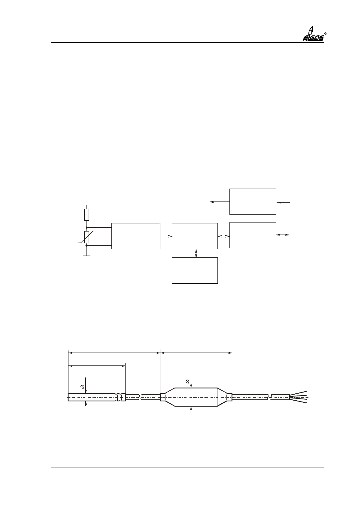
Chyba! Nenalezen zdroj odkazů. shows functional diagram of the transducer. Temperature is
measured by platinum resistive sensor. The signal from the sensor is converted by a high-
resolution analog-to-digital converter into digital form and processed by the microcontroller.
Microcontroller digitally compensates the non-linearity of the sensor using calibration data.
The calibration data is stored in non-volatile EEPROM memory during transducer
manufacturing.
Temperature readout as well as all control functions are accessible via RS 485 interface. The
transducer is capable to measure the temperature on request or continuously in preset time
intervals and store values in its internal memory for later retrieval.
Analog-to-Digital
Converter
Voltage
Regulator
Microcontroller Driver / Receiver
RS485
EEPROM
Memory
Regulated
Power Supply
RS485
Bus
Power
Supply
Uref
Rn
Pt 1000
Uref
Rn
Pt 1000
Figure 1. Functional diagram of the transducer
Physically, the transducer consists of the temperature sensor mounted in stainless-steel stem
50 mm long and the cable. A cylindrical plastic case with electronics is integrated into the
cable.
200 64
17
5.7
50
Figure 2. Dimensional drawing of the transducer.

8
2.2 Device specification
Measurement ranges
Standard range: -25°C to +70°C
Extended range: -40°C to +70°C
Temperature sensor
Platinum resistive element Pt 1000 mounted in ANSI 316L stainless-steel stem, stem diameter:
5.7 mm, stem length: 50 mm standard
Measured media
Liquids and gases, chemically compatible with stainless-steel ANSI 316L
Accuracy
0.2°C within the full measurement range
Includes non-linearity, repeatability and long-term stability.
Electrical connection
Integral shielded cable 4 x 0.25 mm2length 2.6 m with external diameter between 5 to 7 mm.
Other lengths of cable on request. Cable shielding is not connected to the stainless-steel stem.
Power supply
The transducer requires external DC power supply. Transducer terminal voltage must be
between 2.8 to 5.0 V
Power consumption
Standby: 3 μA typical / 10 μA maximum
Measurement and communication: 0.8 mA typical / 4 mA maximum
Power consumption is not dependent on the supply voltage. Power consumption during the
communication depends on the bus impedance.
Start-up time
The transducer is ready to operate 20 ms after power supply is applied.
Communication interface
RS 485, 2-wire, half-duplex, minimum bus impedance 1.5 kΩ. Unterminated bus is
recommended for low-power consumption. Maximum wiring length is 100 m.
Communication protocol

9
Modbus RTU, speed 38400 bit/s, 1 start bit, 8 data bits, no parity, 1 stop bit. Standard functions
supported: Read holding registers (code 03h), Force single coil (code 05h) and Write holding
registers (code 10h). Non-standard functions with codes 45h, 46h, 47h, 48h are implemented.
Datalogging
The transducer is able to measure temprature automatically in regular intervals and store the
measured values in the memory to be retrieved from later on.
Measurement period: adjustable 125 ms to 512 s
Data memory capacity: 80 values
Time base accuracy: 100 ppm
Electric insulation
Resistance between the stem/cable shielding and signal or power supply wires is greater than
10 MΩ at 500 V AC.
Physical specifications
Dimensions: see chapter 2.1
Weight: 100 –150 g (depending on mechanical version)
Environmental specifications
Operating temperature: -40°C to +70°C as sandard
Storage temperature: -40°C to +85°C
Humidity: 0% to 95% relative, without condensation
Protection: IP 65
Vibrations: 10 g sinus 10-2000Hz, ČSN EN 60068-2-6 [3]
Electromagnetic compatibility
Complies with immunity requirements for industrial environments EN 61000-6-2 [2]
Explosion-proof design

10
Equipment with the “i” protection type (intrinsically safe equipment) in compliance with
EN 60079-0 [4] and EN 60079-11 [5]. The certificate registered under No. FTZÚ 18 ATEX 0142X
at the Physical-Technical Testing Institute Ostrava-Radvanice, notified body No. 1026.
Environment classification: Zone 1, 2 according to the EN 60079-14 [6]
Protection class: II1G Ex ia IIC T4 Ga
Safety descriptions:
Ui= 9.9 V
Ci = 2.65 μF
Li= 0 μH
Pi= 1.10 W for Ta<70°C

11
3 Installation
3.1 Mechanical Installation
Temperature transducer is intended for mounting into a thermowell on piping. Operating
position of the transducer is arbitrary. The depth of the thermowell must be 50 mm minimum.
The transducer stem must be inserted to the very bottom of the thermowell and secured by
the fastening nut against pulling-out. It is recommended to fill the space around the stem
inside the thermowell with silicone oil.
3.2 Electrical installation
Wires in the cable or the connector pins carry the following signals:
Signal
Description
color
GND
negative power rail (ground)
green
PWR
positive power rail
brown
DATA-
RS 485 inverted data signal
yellow
DATA+
RS 485 non-inverted signal
white
To operate the transducer, apply DC voltage 2.8 to 5.0 V across PWR and GND terminals and
connect the DATA+, DATA- signals with the corresponding terminals on the host RS 485 port.
The transducer does not provide electrical insulation between the RS 485 bus and the
transducer power supply.
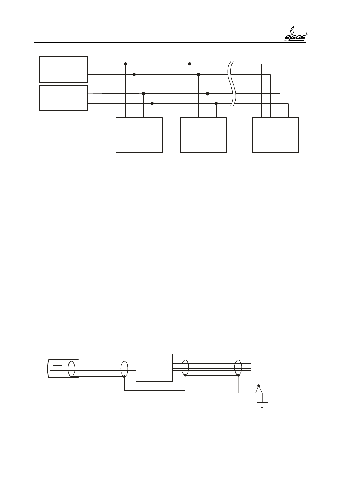
Fig. 3 shows connection of the transducers into the data network. In the RS 485 network, up
to 32 units can be connected at the same time while every unit must have a unique slave
address set.
12
RS 485
Host DATA+
DATA-
Power
Suppl +
-
Transducer Transducer Transducer
DATA+
DATA+
DATA+
DATA-
DATA-
DATA-
PWR
PWR
PWR
GND
GND
GND
....
Fig.3 Transducers connection into data network.
To achieve low power consumption, the transducer uses a special RS 485 driver with limited
slew rate. It is recommended to leave the RS 485 bus unterminated to maintain power
consumption as low as possible. The bus impedance must not be lower than 1.5 kΩ. The length
of the bus should not exceed 100 m. Otherwise, a signal distortion due to reflections can occur
and communication reliability can be deteriorated.
Any standard RS 485 driver / receiver can be used in the host, however for the low power
applications with unterminated bus it is recommended to use a driver with a reduced slew-
rate and a receiver with a high input impedance. Suitable types are MAX 3471 form Maxim
Integrated Products or ADM 483E from Analog Devices.
3.3 Cabling, grounding
The transducer is interconnected with the host using a shielded 4-wire. The cable should not
be laid along power cables, lightning conductors and long metal objects, it should not pass
through areas with strong electro-magnetic disturbances or discharges.
The cable shielding on the side of the host should be connected with ground and with the host
enclosure, if this is metallic. The cable shielding is not connected to the transducer stainless-
steel stem.
Host
Transducer
Fig. 4. Transducer grounding

13
3.4 Power Supply Requirements
The transducer is optimized for very low-power applications. It operates from unregulated
single supply voltage in range 2.8 V to 5.0 V. The supply current is independent from the supply
voltage.
The transducer uses an advanced algorithm to maintain the power consumption at a minimum
level. Only the modules of the transducer which are necessary for the requested function are
powered on. Due to the power consumption management, the supply current varies
significantly depending on the function being performed. Figure 5 shows an example of the
supply current profile. The first part shows a supply current waveform, when a simple query
is received, processed and responded back on the RS 485 bus by the transducer. The second
part shows a supply current waveform during measurement.
Mesurement
Standby
Transmitting response
Receiving query
Standby
Fig. 5 Supply current profile example.

14
The following table summarizes transducer’s typical average supply current for various
measurement periods. The values include power consumption during the measurement and
during necessary communication with the host to initiate the measurement and read
measured values.
Measurement period [s]
Average supply current [µA]
Continuous measurement
800
1
100
10
10
30
6
Standby
3

15
4 Modbus Communication Protocol
The following text describes implementation of the Modbus communication protocol in the
transducer. In order to assure a complete understanding of the operation of the device, the
user should familiarize himself with the Modbus protocol in detail in the reference
literature [1].
Numeric values are given in decimal representation by default. If hexadecimal representation
is used, suffix “h” or “hex” is added.
4.1 Modbus Protocol Overview
The transducer is a Modbus compatible measurement device. The transducer supports 8-bit
Remote Terminal Unit (RTU) data transmission mode with a subset of the standard commands
used by the most Modbus compatible host controllers and a few proprietary commands.
4.1.1 Physical Communication Layer
Communication is carried over the RS 485 bus at baud rate 38400 bit/s. The transmitted
characters have 1 start bit, 8 data bits and no parity, 1 stop bit. These parameters are not
configurable.
4.1.2 Transactions on Modbus networks
The Modbus protocol uses a master/slave technique to control bus access. There can be one
master and up to 247 slave devices. Only the master can initiate a transaction. Transactions
are either a query/response or broadcast/no response. During the query/response transaction
master sends a query to the single slave which process it and responds. During the
broadcast/no response transaction the query is processed by all slave devices but none of
them responds.
Queries, responses and broadcasts are transmitted as frames with a fixed structure. In RTU
mode, frames start with a silent interval of at least 3.5 character times. The first field then
transmitted is the address field followed by a function field, a data field, and CRC field.
Following the last transmitted character, a silent interval of at least 3.5 character times marks
the end of the frame. A new frame can begin after this interval.
The entire message frame must be transmitted as a continuous stream. If a silent interval of
more than 1.5 character times occurs before completion of the frame, the receiving device
ignores the incomplete message and assumes that the next byte will be the address field of a
new message.
Frame format
Start
3.5 char
times
Address
field
1 char
Function
field
1 char
Data
field
n chars
CRC
field
2 chars
End
3.5 char
times

16
Address field
In a query frame, the address field contains a slave address. In a response frame, the address
field contains the address of the responding slave device.
Valid slave addresses are in the range of 1 –247 decimal. Address 0 is reserved for broadcast
messages. Any query message with a slave address of 0 is a broadcast message which all slave
devices process but they do not generate any response.
Function field
In a query frame or a broadcast frame, the function field contains a function code, which
indicates the command to be performed. In a response frame, the function field contains a
copy of the function code received in the query. If the most significant bit in the function field
is set, an error occurred during the query processing. In this case the data field contains an
exception code that explains the particular error.
Data field
The data field contains information that is specific to each individual function.
CRC field
The CRC field contains a 16 bit CRC error check value that is used to verify the integrity of the
message frame.
4.2 Device Specific Features
4.2.1 Service Address
Due to the small dimensions of the transducer, no DIP switches or similar components can be
used for slave address setting. Instead, the slave address is software configurable. In some
cases, however, the slave address can be unknown. Thus, a service address 248 (dec) has been
assigned which the transducer always responds.
Any query frame with a slave address of 248 (dec) the transducer processes and generates a
response. The response is returned with the actual slave address in the address field instead
of the service address 248 (dec). When using the service address, only one transducer may be
connected on the bus with the only exception of the query with the “48h” function code as
described hereinafter in chapter Chyba! Nenalezen zdroj odkazů..
4.2.2 Communication Buffer Length
The transducer implements communication buffer 64 bytes long. If the length of the query
frame exceeds capacity of the buffer, the frame is flushed and no response is generated. If the
master requires such amount of data to be sent which exceeds the capacity of the buffer, the
response is truncated to the total frame length of 64 bytes.
4.2.3 Response Time
The transducer responds 4 to 20 ms after the last character of the query has been received.
The exact time of the response depends on the query length, response length and on the
function processed.

17
4.3 Holding Registers Map
The transducer’s memory is mapped into Modbus holding registers address space
(4xxxx reference). This address space can be read by the Read multiple registers (03h)
command and written by the Write multiple registers (10h) command. The commands are
described in chapter Chyba! Nenalezen zdroj odkazů.. All registers are 16-bit long.
Register numbers shown in the text are in the 4xxxx format which follows the Modicon
protocol specification for data item addressing. The actual register address sent in the Modbus
message frame is the register number shown in the text minus 40001. In other words, the
leading "4" is omitted, and the remaining 4-digit number is decremented by 1.
4.3.1 Holding Registers Map Overview
An overview of all holding registers of the transducer is shown in the table. Description of the
individual registers is in the following paragraphs.
Section
name
Register
number
Register name
Data
type
Access
control
Stored in
EEPROM
Factory configuration
40001
Hardware revision number
uint
FP
N
40002
Software revision number
uint
read only
N
40003 –40004
Serial number
ulong
FP
Y
40005
Sensor type
uint
FP
Y
40006
not used
FP
Y
40007
Units
uint
FP
Y
40008 –40009
Operation range lower limit
float
FP
Y
40010 –40011
Operation range upper limit
float
FP
Y
40012 –40013
Measurement range lower limit
float
FP
Y
40014 –40015
Measurement range upper limit
float
FP
Y
40016
not used
FP
Y
40017
Primary channel offset+gain
uint
FP
Y
40018
Auxiliary channel offset+gain
uint
FP
Y
40019 –40052
Calibration coefficients
float[17]
FP
Y
40053
Coefficient format
uint
FP
Y
40054
not used
FP
Y

18
Holding register map overview - 2nd part
Section
name
Register
number
Register name
Data
type
Access
control
Stored in
EEPROM
Service
config.
40055 –40056
Offset trim
float
SP
Y
40057 –40058
Span trim
float
SP
Y
40059 –40061
not used
SP
Y
User
config.
40062
Modbus slave address
uchar
UP
Y
40063
Group assignment register
uchar
UP
Y
40064
Default operation mode
uchar
UP
Y
40065 –40066
for internal use, do not change
UP
Y
Misc.
40067 –40068
Password
ulong
N
N
40069 –40071
not used
N
N
Measured
variables
40072 –40073
Primary chan. direct readout
float
N
N
40074 –40075
Auxiliary chan. direct readout
float
N
N
40076 –40081
not used
N
N
40082
Temperature
uint
N
N
40083
Status register
uint
N
N
40084
not used
N
N
Datalogger
section
40085
Delay
uint
N
N
40086
Period
uint
N
N
40087
Number of samples
uint
N
N
40088 –40167
Data memory
uint[80]
N
N
Memory locations marked in column “Stored in EEPROM” as “Y” can be stored into the
transducer’s non-volatile EEPROM memory using Write EEPROM function (see paragraph
4.4.3). The stored configuration is recalled after power-up or using Read EEPROM function
(see paragraph Chyba! Nenalezen zdroj odkazů.).
Memory locations marked in column “Access control” as “N” can be read and written with no
restrictions. Memory locations marked as “FP” (Factory password), “SP” (Service password)
and “UP" (User password) can be read without restriction, but can be written only when the
particular section is unlocked using a password. The unlocking procedure is described in
paragraphs Chyba! Nenalezen zdroj odkazů. and Chyba! Nenalezen zdroj odkazů..

19
4.3.2 Factory configuration section
This section contains a basic information about the transducer and calibration data. The
parameters are entered during manufacturing and calibration procedures and cannot be
changed by the user.
Hardware revision number identifies a version of the transducer’s hardware.
Software revision number identifies a version of the transducer’s software. MSB indicates a
main revision number, LSB sub-revision number.
Serial number identifies each transducer individually.
Sensor type. Information about the type of the sensor. Code 10h is used for the temperature
sensor.
Units. Information about physical units used for Measurement and Operation range limits
representation. Code 20h is used for °C.
Measurement range lower and upper limit provide the range of input temperature in which
the transducer is calibrated and in which measures with the specified accuracy.
Operation range lower and upper limit provide the range of input temperature which is
correctly handled by the analog-to-digital converter and numerical calculation. If the
temperature value is outside the measurement range but inside the operation range, the
measurements are still performed but the accuracy is undefined.
Standard values of the limits of the measurement and operation range are shown in the
following table:
Transducer range
(information on label)
Measurement range [°C]
Operation range [°C]
Lower limit
Upper limit
Lower limit
Upper limit
-25°C to +70°C
-25
70
-50
100
-40°C to +70°C
-40
70
-50
100
Primary channel offset and gain provide an offset and gain of the analog-to-digital converter
when primary channel (temperature) is measured. The offset is stored in the MSB of the
register, the gain in the LSB.
Auxiliary channel offset and gain provide an offset and gain of the analog-to-digital converter
when auxiliary channel is measured. The offset is stored in the MSB of the register, the gain in
the LSB.
Calibration coefficients are used to calculate actual temperature using values obtained from
the analog-to-digital converter for the primary and auxiliary channel.
Coefficient format specifies a layout of the coefficients and algorithm for calculation.

20
4.3.3 Service Configuration Section
Parameters in the Service configuration section allows to adjust the offset and span of the
transducer. The default parameters are entered during calibration procedure and can be
changed only by an authorized person using Service password.
Offset trim is an additive constant which defines the shift of the transducer characteristics
relative to the factory calibration data. When the transducer is factory calibrated, the Offset
trim is set to 0.0000. During the field calibration the value can be changed to compensate for
possible characteristics deviation.
Span trim is a multiplicative constant which defines the change of the slope of the transducer
characteristics relative to the factory calibration data. When the transducer is factory
calibrated, the Span trim is set to 1.0000. During the field calibration the value can be changed
to compensate for possible characteristics deviation.
4.3.4 User configuration section
User configuration section contains parameters used for Modbus network setup. The section is
protected by the User password to prevent accidental change of settings.
Modbus slave address contains address to which the transducer responds. When entering a
new address, this is valid immediately after writing to this register.
Group assignment register defines group(s) the transducer belongs to. Transducers belonging
to the same group can be forced to start measurement simultaneously by a single Start
measurement with mask command transmitted as broadcast as described in paragraph 4.5.4.
Default operation mode specifies whether the transducer after power-up or reset starts the
continuous temperature measurement or not. When changing this register, Write EEPROM
command must be issued to store the change in the EEPROM memory.
Code
Default operation mode
00h
standby
01h
continuous measurement
4.3.5 Miscellaneous
This section contains registers used for password manipulation. The password protects write
access to the configuration sections.
Password. After writing correct value to the password registers, desired section can be
unlocked for writing by Unlock section function (see paragraphs Chyba! Nenalezen zdroj
odkazů. a Chyba! Nenalezen zdroj odkazů. ).
4.3.6 Measured variables
In this section, measured and calculated variables are stored. All variables are updated at the
end of each single temperature measurement.
Table of contents
Popular Transducer manuals by other brands

Balluff
Balluff Micropulse BTL5-A series user guide

Mianyang Weibo Electronic
Mianyang Weibo Electronic WBV411S07 user manual

TWK Elektronik
TWK Elektronik PMU-04 user manual

OHIO SEMITRONICS
OHIO SEMITRONICS DCT Series operating instructions

GHM
GHM GRMU 2000 MP operating manual

S+S Regeltechnik
S+S Regeltechnik HYGRASGARD AFF-20 operating instructions


Balluff
Balluff BTL7-A5 Series Condensed guide

Emerson
Emerson Fisher 646 instruction manual

Matelec
Matelec FPC-12571 quick start guide

S+S Regeltechnik
S+S Regeltechnik PHOTASGARD FSHKM Operating Instructions, Mounting & Installation

Thyracont
Thyracont VSH87PN operating instructions

turck
turck IM12-TI02-2TCURTDR-2I Series quick start guide