Emerson Fisher 646 User manual

www.Fisher.com
Fisherr646 Electro‐Pneumatic Transducer
Contents
Introduction 1.................................
Scope of Manual 1.............................
Description 3.................................
Specifications 4...............................
Educational Services 4.........................
Installation 4..................................
Hazardous Area Classifications and
Special Instructions for “Safe Use” and
Installation in Hazardous Locations 5...........
CSA 5....................................
FM 6.....................................
ATEX 6...................................
IECEx 7...................................
Mounting 8..................................
Pneumatic Connections 9......................
Supply Pressure Requirements 9.............
Diagnostic Connections 10..................
Vent 10..................................
Electrical Connections 10.......................
Operating Information 12........................
Calibration 12................................
Equipment Required 12.....................
Calibration Procedure 12....................
Principle of Operation 13........................
Maintenance 14................................
Troubleshooting 14............................
Converter Module Replacement 15..............
Relay Maintenance 16..........................
Figure 1. Fisher 646 Electro‐Pneumatic Transducer
Mounted on a Sliding‐Stem Actuator
W6783‐1/IL
Parts Ordering 18...............................
Parts Kits 18...................................
Parts List 18...................................
Loop Schematics 22.............................
Introduction
Scope of Manual
This instruction manual provides installation, operation, maintenance, and parts ordering information for the Fisher
646 transducer. Refer to separate manuals for instructions covering equipment used with the transducer.
Do not install, operate or maintain a 646 electro‐pneumatic transducer without being fully trained and qualified in
valve, actuator and accessory installation, operation and maintenance. To avoid personal injury or property damage it
is important to carefully read, understand, and follow all of the contents of this manual, including all safety cautions
and warnings. If you have any questions about these instructions, contact your Emerson Process Management sales
office before proceeding.
Instruction Manual
D101351X012
646 Transducer
January 2015

Instruction Manual
D101351X012
646 Transducer
January 2015
2
Table 1. Specifications
Input Signal
4-20 mA DC, constant current with 30 VDC maximum
compliance voltage
Equivalent Circuit
The 646 equivalent circuit is a series circuit consisting
of a constant voltage drop (battery) of approximately
2.1 VDC and a total resistance of 143 ohms. Input is
shunted by three 6.8 V zener diodes (see figure 6).
Output Signal
0.2 to 1.0 bar (3 to 15 psig) direct acting only
Supply Pressure(1)
Recommended: 1.4 bar (20 psig)
Minimum: 1.4 bar (20 psig)
Maximum: 3.4 bar (50 psig)
Average Steady‐State Air Consumption(2)(3)
0.08 m3/hr (3 scfh) at 1.4 bar (20 psi) supply pressure
Maximum Output Air Capacity(2)
8.0 m3/hr (300 scfh) at 1.4 bar (20 psig) supply
pressure
Performance(4)
Reference Accuracy: ±0.5% of full scale output span;
includes combined effects of hysteresis, linearity, and
deadband
Independent Linearity: ±0.5% of full scale output span
Hysteresis: 0.4% of full scale output span
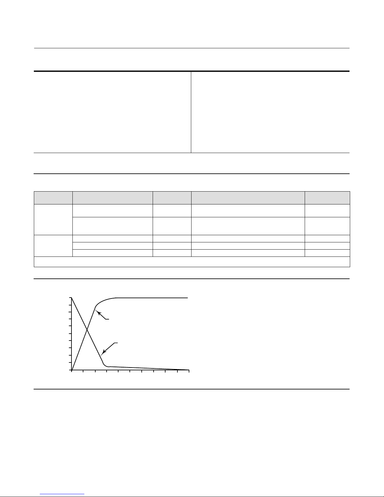
Frequency Response: Gain is attenuated 3 dB at 10 Hz
with transducer output signal piped to a typical
instrument input
Temperature Effect: ±4% of full scale output span per
55_C (100_F) change
Supply Pressure Effect: 0.2% of full scale output span
per psi supply pressure change
Vibration Effect: Less than 1% of full scale output span
when tested to SAMA PMC 31.1, Condition 3
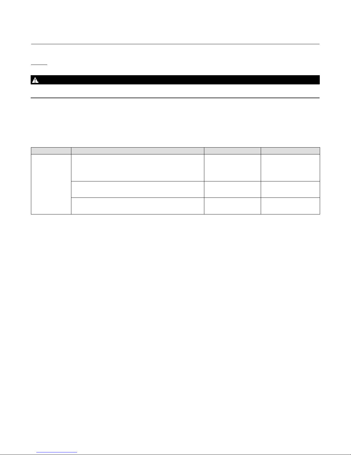
Electromagnetic Compatibility
Meets EN 61326‐1 (First Edition)
Immunity—Industrial locations per Table 2 of
the EN 61326‐1 standard. Performance is
shown in table 2 below.
Emissions—Class A
ISM equipment rating: Group 1, Class A
Operating Ambient Temperature Limits(1)
-40 to 71_C (-40 to +160_F)
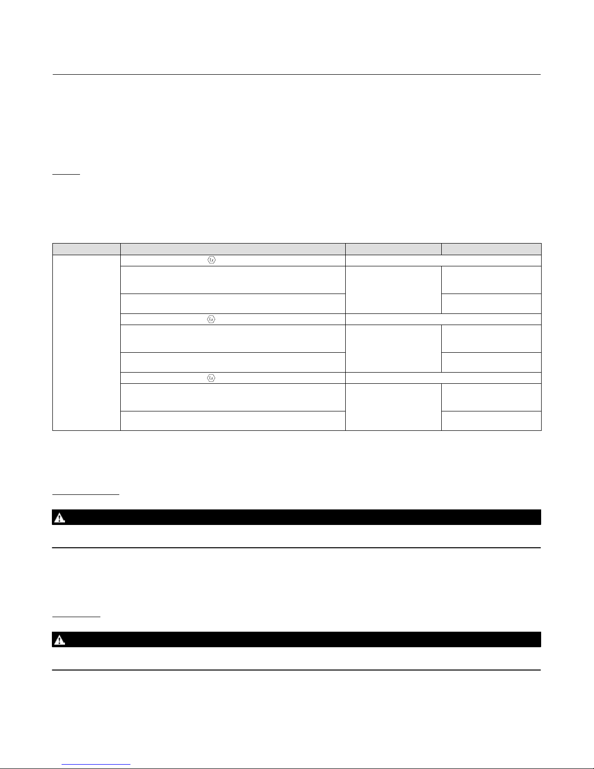
Electrical Classification
CSA—Intrinsically Safe, Explosion proof, Type n,
Dust‐Ignition proof, DIV 2
FM—Intrinsically Safe, Explosion proof, Type n,
Non‐incendive, Dust‐Ignition proof
ATEX—Intrinsically Safe, Flameproof, Type n
IECEx—Intrinsically Safe, Flameproof, Type n
Refer to Hazardous Area Classifications and Special
Instructions for the “Safe Use” and Installation in
Hazardous Locations starting on page 5 for
additional information.
Housing
CSA—Type 3 Encl.
FM—NEMA 3, IP54
ATEX—IP64
IECEx—IP54
Mount instrument with vent on side or bottom if
weatherproofing is a concern.
Other Classifications/Certifications
INMETRO— National Institute of Metrology, Quality
and Technology (Brazil)
KGS— Korea Gas Safety Corporation (South Korea)
Contact your Emerson Process Management sales
office for classification/certification specific
information
Connections
Supply and Output Pressure: 1/4 NPT internal
connection
Vent: 1/4 NPT internal
Electrical: 1/2‐14 NPT conduit connection
Wire Size: 18 to 22 AWG
Adjustments
Zero and Span: Trim potentiometers (20 turn) for
zero and span adjustments are located under the
housing cap (see figure 7)
-continued-

Instruction Manual
D101351X012
646 Transducer
January 2015
3
Table 1. Specifications (Continued)
Mounting Position
Any position is acceptable for standard pipestand,
panel, or actuator mounting. For weatherproof
housing, mount the transducer so the vent can drain.
Approximate Weight (Transducer Only)
1.6 kg (3.5 pounds)
Actuator Stroking Time
See figure 2
Declaration of SEP
Fisher Controls International LLC declares this
product to be in compliance with Article 3 paragraph
3 of the Pressure Equipment Directive (PED) 97 / 23 /
EC. It was designed and manufactured in accordance
with Sound Engineering Practice (SEP) and cannot
bear the CE marking related to PED compliance.
However, the product may bear the CE marking to
indicate compliance with other applicable European
Community Directives.
NOTE: Specialized instrument terms are defined in ANSI/ISA Standard 51.1 ‐ Process Instrument Terminology.
1. The pressure and temperature limits in this document and any applicable standard or code limitation should not be exceeded.
2. Normal m3/hr—Normal cubic meters per hour (0_C and 1.01325 bar, absolute). Scfh—Standard cubic feet per hour (60_F and 14.7 psia).
3. Average flow rate determined at 12 mA and 0.6 bar (9 psig) output.
4. Performance values are obtained using a transducer with a 4 to 20 mA DC input signal and a 0.2 to 1.0 ba (r3 to 15 psig) output signal at an ambient temperature of 24_C (75_F).
Table 2. EMC Summary Results—Immunity
Port Phenomenon Basic Standard Test Level Performance
Criteria(1)
Enclosure
Electrostatic discharge (ESD) IEC 61000‐4‐2 4 kV contact
8 kV air A
Radiated EM field IEC 61000‐4‐3
80 to 1000 MHz @ 10V/m with 1 kHz AM at 80%
1400 to 2000 MHz @ 3V/m with 1 kHz AM at 80%
2000 to 2700 MHz @ 1V/m with 1 kHz AM at 80%
A
I/O signal/control
Burst (fast transients) IEC 61000‐4‐4 1 kV A
Surge IEC 61000‐4‐5 1 kV (line to ground only, each) B
Conducted RF IEC 61000‐4‐6 150 kHz to 80 MHz at 3 Vrms A
1. A = No degradation during testing. B = Temporary degradation during testing, but is self‐recovering.
Specification Limit = +/‐ 1% of span.
Figure 2. Output‐Time Relationships for Fisher 646 Transducer
LOADING
EXHAUSTING
TIME (%)
0 102030405060708090100
0
10
20
30
40
50
60
70
80
90
100
OUTPUT
(% OF 646 OUTPUT SPAN)
A6815 / IL
Description
The transducer, shown in figure 1, receives a 4-20 milliampere DC input signal and transmits a proportional 0.2 to 1.0
bar (3 to 15 psig) pneumatic output pressure to a final control element. A typical application is in electronic control
loops where the final control element is a control valve assembly that is pneumatically operated. The input signal and
output pressure range of the transducer is indicated on the nameplate attached to the housing.

Instruction Manual
D101351X012
646 Transducer
January 2015
4
CAUTION
Dropping or rough handling of the transducer can cause damage to the converter module resulting in a shifted output or a
minimum output.
WARNING
This product does not meet third party approvals (CSA, FM, ATEX, or IECEx) for use with natural gas as the supply medium.
Use of natural gas as the supply medium can damage the instrument and result in personal injury or property damage from
fire or explosion.
Should you need an instrument for use with natural gas, Fisher 846 and i2P‐100 electro‐pneumatic transducers both meet
third party approvals for use with natural gas as the supply medium. Contact your Emerson Process Management sales
office for information on these products.
Specifications
Specifications for the 646 transducer are listed in table 1.
Educational Services
For information on available courses for the 646 electro‐pneumatic transducer, as well as a variety of other products,
contact:
Emerson Process Management
Educational Services, Registration
Phone: +1-641‐754‐3771 or +1-800‐338‐8158
e‐mail: [email protected]
http://www.emersonprocess.com/education
Installation
WARNING
Always wear protective clothing, gloves, and eyewear when performing any installation operations to avoid personal
injury.
Check with your process or safety engineer for any additional measures that must be taken to protect against process
media.
If installing into an existing application, also refer to the WARNING at the beginning of the Maintenance section in this
instruction manual.

Instruction Manual
D101351X012
646 Transducer
January 2015
5
Hazardous Area Classifications and Special Instructions for “Safe Use” and
Installation in Hazardous Locations
Certain nameplates may carry more than one approval, and each approval may have unique installation/wiring
requirements and/or conditions of “safe use”. These special instructions for “safe use” are in addition to, and may
override, the standard installation procedures. Special instructions are listed by approval.
Note
This information supplements the nameplate markings affixed to the product.
Always refer to the nameplate itself to identify the appropriate certification. Contact your Emerson Process Management sales
office for approval/certification information not listed here.
WARNING
Failure to follow these conditions of “safe use” could result in personal injury or property damage from fire or explosion
and area re‐classification.
CSA
Intrinsically Safe, Explosion proof, Type n Dust‐Ignition proof, DIV 2
No special conditions for safe use.
Refer to table 3 for additional information.
Table 3. Hazardous Area Classifications—CSA (Canada)
Certification Body Certification Obtained Entity Rating Temperature Code
CSA
Intrinsically Safe
Ex ia IIC T4/T5 per drawing GE28591 (see figure 12)
Ex ia Intrinsically Safe
Class I, II, Division 1 GP A,B,C,D,E,F,G T4/T5
per drawing GE28591 (see figure 12)
Vmax = 30 VDC
Imax = 150 mA
Pi = 1.0 W
Ci = 0 nF
Li = 0 mH
T4 (Tamb ≤71°C)
T5 (Tamb ≤40°C)
Explosion-proof
Ex d IIC T6
Class I, Division I, GP A,B,C,D T6
- - - T6 (Tamb ≤71°C)
Type n
Ex nL IIC T6 - - - T6 (Tamb ≤71°C)
Class I, Division 2, GP A,B,C,D T6
Class II, Division 1, Groups E,F,G T6
Class II, Division 2, GP F,G T6
- - - T6 (Tamb ≤71°C)

Instruction Manual
D101351X012
646 Transducer
January 2015
6
FM
Intrinsically Safe, Explosion proof, Type n Non‐incendive, Dust‐Ignition proof
No special conditions for safe use.
Refer to table 4 for additional information.
Table 4. Hazardous Area Classifications—FM (United States)
Certification Body Certification Obtained Entity Rating Temperature Code
FM
Intrinsically Safe
Class 1 Zone 0 AEx ia IIC T4/T5
per drawing GE28590 (see figure 13)
Class I, II, III Division 1 GP A,B,C,D,E,F,G
T4/T5 per drawing GE28590 (see figure 13)
Vmax = 30 VDC
Imax = 150 mA
Pi = 1.0 W
Ci = 0 nF
Li = 0 mH
T4 (Tamb ≤71°C)
T5 (Tamb ≤40°C)
Explosion-proof
Class 1 Zone 1 AEx d IIC T6
Class I, Division I, GP A,B,C,D T6
- - - T6 (Tamb ≤71°C)
Type n
CL 1 Zone 2 AEx nL IIC T6 - - - T6 (Tamb ≤71°C)
Class I, Division 2, GP A,B,C,D T6
Class II, Division 1, Groups E,F,G T6
Class II, Division 2, GP F,G T6
- - - T6 (Tamb ≤71°C)
ATEX
Standards Used for Certification
EN 60079-0: 2012 EN 60079-31: 2009
EN 60079-1: 2007 EN 61241-0: 2006
EN 60079-11: 2012 EN 61241-1: 2004
EN 60079-15: 2010 EN 61241-11: 2006
Special Conditions for Safe Use
Intrinsically Safe
This equipment is intrinsically safe and can be used in potentially explosive atmospheres.
The electrical parameters of certified equipment which can be connected to the device must not exceed the following
values: U0≤30 VDC ; I0≤150 mA ; P0≤1 W
Ambient temperature: T5, at Tamb = 40_C ; T4, at Tamb = 71_C
Flameproof
The flame path is other than required by EN 60079‐1. Contact the manufacturer for information on the dimensions of
the flameproof joints.
Electrical connections are typically made using either cable or conduit.
D If using a cable connection, the cable entry device shall be certified in type of explosion protection flameproof
enclosure “d”, suitable for the conditions of use and correctly installed.
For ambient temperatures over 70_C, cables and cable glands suitable for at least 90_C shall be used.

Instruction Manual
D101351X012
646 Transducer
January 2015
7
D If using a rigid conduit connection, an Ex d certified sealing device such as a conduit seal with setting compound
shall be provided immediately to the entrance of the enclosure.
For ambient temperatures over 70_C, the wiring and setting compound in the conduit seal shall be suitable for at least
90_C.
Type n
No special conditions for safe use.
Refer to table 5 for additional information.
Table 5. Hazardous Area Classifications—ATEX
Certificate Certification Obtained Entity Rating Temperature Code
ATEX
II 1 G & D
Intrinsically Safe
Gas
Ex ia IIC T4/T5 Ga
Ui = 30 VDC
Ii = 150 mA
Pi = 1.0 W
Ci = 0 nF
Li = 0 mH
T4 (Tamb ≤71°C)
T5 (Tamb ≤40°C)
Dust
Ex ia IIIC Da T155 °C (Tamb ≤71°C) / T124°C (Tamb ≤40°C) - - -
II 2 G & D
Flameproof
Gas
Ex d IIC T6 Gb - - -
T6 (Tamb ≤71°C)
Dust
Ex tb IIIC T74 °C Db (Tamb ≤71°C) - - -
II 3 G & D
Type n
Gas
Ex nA IIC T6 Gc - - -
T6 (Tamb ≤71°C)
Dust
Ex tc IIIC T74 °C Dc (Tamb ≤71°C) - - -
IECEx
Conditions of Certification
Intrinsically Safe
WARNING
Substitution of components may impair intrinsic safety.
-40_C ≤Ta ≤+71_C ; T5 (Ta ≤+40_C) ; T4 (Ta ≤+71_C)
Entity Parameters: Ui=30 V , li = 150 mA , Pi = 1.0 W , Ci = 0 nF , Li = 0 mH
Flameproof
WARNING
Disconnect power before opening.
-40_C ≤Ta ≤+71_C ; T6 (Ta ≤+71_C)

Instruction Manual
D101351X012
646 Transducer
January 2015
8
Type n
WARNING
Disconnect power before opening.
-40_C ≤Ta ≤+71_C ; T6 (Ta ≤+71_C)
Refer to table 6 for additional information.
Table 6. Hazardous Area Classifications—IECEx
Certificate Certification Obtained Entity Rating Temperature Code
IECEx
Intrinsically Safe
Gas
Ex ia IIC T4/T5 Ga
Ui = 30 VDC
Ii = 150 mA
Pi = 1.0 W
Ci = 0 nF
Li = 0 mH
T4 (Tamb ≤71°C)
T5 (Tamb ≤40°C)
Flameproof
Gas
Ex d IIC T6 Gb
- - - T6 (Tamb ≤71°C)
Type n
Gas
Ex nA IIC T6 Gc
- - - T6 (Tamb ≤71°C)
Mounting
When a transducer is ordered as part of a control valve assembly, the factory mounts the transducer on the actuator
and connects the necessary tubing, then adjusts the transducer as specified on the order.
Transducers also can be ordered separately for mounting on a control valve assembly already in service, or for
mounting on a 2 inch diameter pipestand, a flat surface, or a bulkhead. The transducer may be ordered either with or
without mounting parts. Mounting parts include a mounting plate and bolts and, if ordered for pipestand mounting, a
pipe clamp. Tubing is not included if the transducer is not factory mounted. Use 10 mm (3/8‐inch) diameter tubing for
all input and output connections. The length of tubing between the transducer output and the final control element
should be as short as possible. Transducer overall dimensions are shown in figure 3. If weatherproofing is required,
mount the transducer so that the vent can drain. Do not allow moisture or condensate to collect in the vent.

Instruction Manual
D101351X012
646 Transducer
January 2015
9
Figure 3. Dimensions and Connections
35
(1.38)
6.4
(.25)
127.0
(5.00)
72.8
(2.86
)
102.1
(4.02
)
152.4
(6.00) 152.4
(6.00)
79.2
(3.12)
47.8
(1.88)
127.0
(5.00)
9.5
(.38)
9.7
(0.38)
mm
(INCH)
CENTERLINE
OF ACTUATOR
EXHAUST
1/4‐18 NPT
OPTIONAL OUTPUT
OR GAUGE CONN
1/4‐18 NPT
OUTPUT CONN
1/2‐14 NPT
CONDUIT CONN
OPTIONAL
GAUGE
67CFR
1/4‐18 NPT
SUPPLY
CONN
CAP
REMOVAL
CLEARANCE
57
(2.25)
106.4
(4.19)
62.0
(2.44)
38B3958‐A
A6816‐1 / IL
41.1
(1.62)
Pneumatic Connections
As shown in figure 3, all pressure connections on the transducer are 1/4 NPT internal connections. Use 10 mm
(3/8‐inch) tubing for all pressure connections. Refer to the vent subsection below for remote vent connections.
Supply Pressure Requirements
WARNING
Severe personal injury or property damage may occur if the instrument air supply is not clean, dry and oil‐free. While use
and regular maintenance of a filter that removes particles larger than 40 micrometers in diameter will suffice in most
applications, check with an Emerson Process Management field office and industry instrument air quality standards for use
with corrosive air or if you are unsure about the proper amount or method of air filtration or filter maintenance.
Supply pressure must be clean, dry air. Use a Fisher 67CFR filter regulator with standard 5 micrometer filter, or
equivalent, to filter and regulate supply air. The filter regulator can be mounted on a bracket with the transducer as
shown in figure 11 or mounted on the actuator mounting boss. An output pressure gauge may be installed on the
regulator to indicate the supply pressure to the transducer. Also, as an aid for calibration, a second gauge may be
installed on the transducer to indicate transducer output pressure.

Instruction Manual
D101351X012
646 Transducer
January 2015
10
Connect the nearest suitable supply source to the 1/4 NPT IN connection on the filter regulator (if furnished) or to the
1/4 NPT SUPPLY connection on the transducer case (if the filter regulator is not attached).
Diagnostic Connections
To support diagnostic testing of valve/actuator/positioner packages, special connectors and hardware are available.
Typical connector installations are shown in figure 4. The hardware used includes a 1/4 NPT pipe nipple and pipe tee
with a 1/8 NPT pipe bushing for the connector. The connector consists of a 1/8 NPT body and body protector.
Figure 4. Diagnostics Hookup for the Fisher 646 Transducer
BODY
BODY PROTECTOR
PIPE BUSHING
BODY PROTECTOR
BODY
PIPE BUSHING
PIPE TEE
PIPE NIPPLE
GAUGE
STEM
PROVIDED WHEN
GAUGE IS SPECIFIED
SIDE OUTPUTFRONT OUTPUT
12B8040‐A
B2395‐1/IL
Note
If the 646 transducer is used in a valve assembly with a positioner, no hook‐up for diagnostic testing is required for the 646. The
hook‐up for diagnostic testing should be installed at the positioner.
Install the connectors and hardware between the 646 transducer and the actuator.
1. Before assembling the pipe nipple, pipe tee, pipe bushings, actuator piping, and connector body, apply sealant to
all threads.
2. Turn the pipe tee to position the connector body and body protector for easy access when doing diagnostic testing.
Vent
If a remote vent is required, the vent line must be as short as possible with a minimum number of bends and elbows.
To connect a remote vent, remove the plastic vent (key 41, figure 10). The vent connection is 1/4 NPT internal. Use
3/8‐inch tubing to provide a remote vent.
Electrical Connections
WARNING
For explosion‐proof applications, disconnect power before removing the housing cap.

Instruction Manual
D101351X012
646 Transducer
January 2015
11
For explosion‐proof Class 1, Division 1 applications using metal conduit, install a conduit seal no more than 457 mm (18
inches) from the transducer. Personal injury or property damage may result from explosion if the seal is not installed. For
other explosion‐proof applications, install the transducer in accordance with applicable codes.
WARNING
For proper wiring and installation for intrinsically safe installations, refer to the nameplate affixed to the product and loop
schematics for CSA and FM (figure 12 and 13), or to instructions provided by the barrier manufacturer.
WARNING
Select wiring and/or cable glands that are rated for the environment of use (such as hazardous area, ingress protection, and
temperature). Failure to use properly rated wiring and/or cable glands can result in personal injury or property damage
from fire or explosion.
Wiring connections must be in accordance with local, regional, and national codes for any given hazardous area approval.
Failure to follow the local, regional, and national codes could result in personal injury or property damage from fire or
explosion.
Use the 1/2‐14 NPT conduit connection, shown in figure 3, for installation of field wiring. For Class I, Division I
explosion‐proof applications, install rigid metal conduit and a seal no more than 457 mm (18 inches) from the
transducer. Also, install conduit using local and national electrical codes which apply to the application.
Refer to figures 5, 6, and 7 when connecting field wiring from the control device to the transducer. Connect the
positive wire from the control device to the transducer “+” terminal and, the negative wire from the control device to
the transducer “-” terminal. Do not overtighten the terminal screws. Maximum torque is 0.45 NSm (4 lbfSin.). Connect
the transducer grounding terminal to earth ground. Grounding terminals are provided both inside and outside the
transducer housing.
Figure 5. Typical Field Wiring Diagram
+
-
+
−−+
1
CONTROL
DEVICE
TRANSDUCER
HOUSING
TERMINAL BLOCK
FIELD WIRING
EARTH GROUND
NOTE:
1 FOR TROUBLESHOOTING OR MONITORING OPERATION,
AN INDICATING DEVICE CAN BE A VOLTMETER ACROSS
A 250 OHM RESISTOR OR A CURRENT METER.
A3875/IL
Figure 6. Equivalent Circuit
A6013/IL
6.8V 6.8V 6.8V 0.7V
0.7V
0.7V
60 Ohms
60 Ohms
23 Ohms
4-20 mA
+
‐

Instruction Manual
D101351X012
646 Transducer
January 2015
12
Figure 7. Zero and Span Adjustments and Terminal Block Connections (Cap Removed)
PRINTED
WIRING
BOARDS ZERO ADJUSTMENT
SPAN ADJUSTMENT
TRANSDUCER
HOUSING
FIELD
WIRING
CONNECTION
+
−
A3876‐2/IL
Operating Information
The normal mode of operation for the 646 transducer requires that the pneumatic output pressure be piped to the
final control element. If this is not done the resulting pneumatic output will vent to the atmosphere.
Calibration
WARNING
On explosion‐proof instruments, remove electrical power before removing the housing cap in a hazardous area. Personal
injury or property damage may result from fire or explosion if power is applied to the transducer with the cap removed in a
hazardous area.
For intrinsically safe areas, current monitoring during operation must be with a meter approved for use in hazardous areas.
Equipment Required
Choose a current or voltage source that is capable, without switching ranges, of driving the transducer through its
entire input range. Switching ranges on a current or voltage source will produce spikes or mid‐scale reverses in the
input signal presented to the transducer, causing errors. The current source should be capable of delivering 30 mA
with 30 VDC maximum compliance voltage.
Calibration Procedure
WARNING
For critical processes, this calibration procedure requires taking the final control element out of service. To avoid personal
injury or property damage due to an uncontrolled process, provide some temporary means of process control before
beginning the calibration procedure.

Instruction Manual
D101351X012
646 Transducer
January 2015
13
Refer to figure 7 for adjustment locations.
1. If a current source other than the control device is used as the input source, disconnect the control device and
connect the current source positive terminal to the transducer “+” terminal and the current source negative
terminal to the transducer “-” terminal.
If an external meter is used, connect the current source positive terminal to the transducer “+” terminal. Connect
the meter positive terminal to the transducer “-” terminal and the meter negative terminal to the current source
negative terminal as shown in figure 5.
2. Check the supply pressure to ensure it is at the recommended pressure listed on the transducer nameplate.
3. Adjust the input current to 4.00 milliamperes DC.
4. The output pressure should be 0.2 bar (3 psig). If not, adjust the ZERO potentiometer until the output pressure is
0.2 bar (3 psig).
5. Adjust the input current to 20.00 milliamperes DC.
6. The output pressure should be 1.0 bar (15 psig). If not, adjust the SPAN potentiometer until the output pressure is
0.8 bar (15 psig).
7. Repeat steps 2 through 6 until the output pressure is within the referenced accuracy requirements without further
adjustment.
8. If a current source other than the control device was used, disconnect the current source and reconnect the control
device.
Principle of Operation
The converter module receives a standard DC current input signal from a control device to operate coils in a force
balanced beam system which in turn, controls bleed air through an integral nozzle/flapper arrangement. The nozzle
pressure provides the input signal to operate the relay as shown in figure 8. Relay output pressure is applied, through
tubing, directly to the final control element or valve/actuator assembly.
Figure 8. Fisher 646 Transducer Schematic
COIL
ZERO AND
SPAN CIRCUIT
DC CURRENT
INPUT
SIGNAL
CONVERTER
MODULE
RELAY
DIAPHRAGM
EXHAUST
DIAPHRAGM
OUTPUT PRESSURE
MAGNET
BEAM
FLAPPER
NOZZLE
RESTRICTION
VALVE PLUG
SUPPLY PRESSURE
A3877‐1/IL

Instruction Manual
D101351X012
646 Transducer
January 2015
14
Maintenance
The normal mode of operation for the 646 transducer requires that the pneumatic output pressure be piped to the
final control element. If this is not done the resulting pneumatic output will vent to the atmosphere.
Due to normal wear or damage from external sources such as debris in the supply medium, periodic maintenance or
repair of the transducer may be necessary. Maintenance of the transducer consists of troubleshooting, removal for
inspection, and replacement of component parts.
WARNING
To avoid personal injury or property damage from the sudden release of pressure:
D Always wear protective clothing, gloves, and eyewear when performing any maintenance operations.
D Do not remove the actuator from the valve while the valve is still pressurized.
D Disconnect any operating lines providing air pressure, electric power, or a control signal to the actuator. Be sure the
actuator cannot suddenly open or close the valve.
D Use bypass valves or completely shut off the process to isolate the valve from process pressure. Relieve process pressure
on both sides of the valve.
D Use lock‐out procedures to be sure that the above measures stay in effect while you work on the equipment.
D Do not open when an explosive dust atmosphere is present.
D Check with your process or safety engineer for any additional measures that must be taken to protect against process
media.
WARNING
For explosion proof applications, disconnect power before removing the housing cap. Personal injury or property damage
may result if power is not disconnected.
WARNING
The presence of Emerson Process Management personnel and approval agency personnel may be required if you service
(other than normal, routine maintenance, such as calibration) or replace components on a 646 transducer that carries a
third‐party approval. When you replace components, use only components specified by the factory. Substitution with
other components may void the third‐party approval and result in personal injury or property damage. Also, always use
proper component replacement techniques, as presented in this manual. Improper techniques can cause poor quality
repairs and impair the safety features of the device.
The converter module should never be disassembled because the magnetism in the coils will decrease permanently. If
troubleshooting or alignment attempts indicate a faulty converter module, replace the module or return the transducer to
your Emerson Process Management sales office for repair.
Troubleshooting
The following procedures require taking the control valve/actuator assembly out of service. Provide some temporary
means of process control before taking the control valve out of service.

Instruction Manual
D101351X012
646 Transducer
January 2015
15
Electrical
1. Ensure terminal lug connections from the control device to the transducer are of the correct polarity (refer to the
electrical connection procedures in the Installation section).
2. At the transducer, ensure that the milliampere DC signal is applied and that it is within the 4 to 20 milliampere
range.
Pneumatic
Provide a 4‐30 milliampere DC current source, supply pressure, and a gauge to monitor the output pressure when
checking transducer operation. Refer to figure 10 for key number locations.
1. Ensure that supply pressure to the transducer is a consistent 1.4 bar (20 psig).
2. If a filter/regulator is used, ensure that it is working correctly. If not, ensure the dripwell is not plugged because of
excessive moisture accumulation. If necessary, drain off any moisture, and clean or replace the filter element.
3. Force the converter module to maximum output pressure with a 30 milliampere DC signal. Output pressure should
build up to the approximate value of the supply pressure.
4. When the input current is removed, the transducer output pressure should drop to less than 0.14 bar (2 psig). If it
does not, check to ensure the vent and exhaust air passageway is free from foreign material.
5. To inspect the relay assembly, refer to the relay maintenance procedures.
Converter Module Replacement
Removal
Refer to figure 10 for key number locations.
1. Remove the housing cap (key 4).
2. Note the location of the wires, then remove the electrical wiring from the terminal block mounted on the printed
wiring board.
3. Remove the two screws (key 19) and remove the converter module and wire guide (key 42) from the housing.
4. Inspect the O‐ring (key 18) and replace if necessary.
Replacement
1. Lubricate the O‐ring (key 18) with a lubricating compound such as key 20 before replacing the converter module in
the housing.
2. Insert the converter module and wire guide (key 42) into position in the housing (key 3). Replace the two screws
(key 19) and tighten them.
3. Replace the electrical wiring removed in step 2 of the removal procedures. Do not overtighten the terminal screws.
Maximum torque is 0.45 NSm (4 lbfSin).
4. Electrically calibrate the module following the procedures in the Calibration section.
5. Replace the housing cap (key 4).

Instruction Manual
D101351X012
646 Transducer
January 2015
16
Relay Maintenance
Refer to figure 10 for key number locations.
Removal
1. Remove the four mounting screws (key 7) and remove the relay from the transducer. Be careful not to lose the bias
spring (key 13) and input diaphragm (key 9).
2. Remove the body block (key 2) from the relay body assembly (key 1).
3. Remove the exhaust port assembly (key 10) from the relay assembly.
4. Remove the body plug (key 5) that holds the inner valve spring (key 12) and valve plug (key 14) in place.
5. Inspect the springs, exhaust seat, valve plug, and other parts for wear or damage; replace as necessary. Note: the
valve plug supply seat is an insert in the relay body (key 1). If this insert is bad, replace the relay body.
6. Ensure that the fixed restriction in the transducer housing is clear of foreign matter.
7. Make sure all parts of the relay are clean and that all passages are clear of foreign matter.
Assembly
1. Assemble the inner valve spring (key 12) onto the body plug (key 5) and fit the valve plug (key 14) onto the inner
valve spring as shown in figure 9. To assure best alignment between the valve plug, inner valve spring, and body
plug; fit the valve plug onto the inner valve spring so that one of the three tabs at the base of the valve plug sets at
the end of the last coil of the inner valve spring.
Figure 9. Valve Plug, Inner Valve Spring and Body Plug Assembly
VALVE PLUG
(KEY 14)
ONE OF THREE
TABS ON VALVE PLUG
END OF SPRING COIL
BODY PLUG
(KEY 5)
O‐RING
(KEY 8)
INNER VALVE
SPRING
(KEY 12)
A6057‐1/IL

Instruction Manual
D101351X012
646 Transducer
January 2015
17
2. Insert the assembled valve plug, inner valve spring, and body plug into the relay body (key 1). Compress the spring
and thread the body plug (key 5) into place. Then, tighten the body plug.
3. Insert two of the mounting screws (key 7) into two opposite holes of the relay body (key 1). Hold the screws in place
while assembling the following parts on the relay body. The screws serve as studs to align the parts as they are being
assembled.
4. When replacing the exhaust port assembly (key 10), make sure all passages and screw holes are aligned and that
the hole in the center of the exhaust port assembly fits over the valve plug (key 14). Place the exhaust port assembly
on the relay body (key 1). Hold assembled parts in place.
5. Make sure the tabs on the body block (key 2) align with the tabs on the relay body (key 1) and that the side with 5
holes faces the relay body. Place the body block on the assembled parts. Hold assembled parts in place.
6. When replacing the input diaphragm (key 9), make sure all passages and screw holes are aligned. Place the input
diaphragm on the body block (key 2). Hold assembled parts in place.
7. Install the bias spring (key 13) into the transducer housing assembly (key 3). Make sure the tabs on the body block
and relay body align with the tab on the transducer housing assembly. Place the assembled parts onto the
transducer housing assembly. Thread the two mounting screws (key 7) into the transducer housing assembly.
Install the remaining two mounting screws. Tighten all mounting screws to 2 NSm (20 lbfSin).
8. Perform the procedures in the Calibration section.

Instruction Manual
D101351X012
646 Transducer
January 2015
18
Parts Ordering
A serial number is assigned to each transducer and stamped on the nameplate. Always refer to this serial number when
corresponding with your Emerson Process Management sales office regarding spare parts or technical information.
When ordering replacement parts, also specify the complete 11‐character part number from the Parts list.
WARNING
Use only genuine Fisher replacement parts. Components that are not supplied by Emerson Process Management should
not, under any circumstances, be used in any Fisher instrument. Use of components not supplied by Emerson Process
Management may void your warranty, might adversely affect the performance of the instrument, and could result in
personal injury or property damage.
Parts Kits
Description Part Number
646 Transducer Repair Kit
Includes keys 6, 8, 9, 10, 12, 13, 14, and
18. The O‐ring for the converter module
is also included in the kit. R646X000012
Parts List
Note
Part numbers are shown for recommended spares only. For part
numbers not shown, contact your Emerson Process Management sales
office.
Key Description
1 Relay body assembly
2 Body block, aluminum
3 Housing assembly
1/2 NPT conduit connection
4 Housing Cap, aluminum
5 Body plug, aluminum
Key Description Part Number
6* O‐ring, nitrile 1E5477X0062
7 Machine screw, stainless steel (4 req'd)
8* O‐ring, nitrile 1H8762X0012
9* Input diaphragm, nitrile 21B2362X012
10 Exhaust port assembly
12 Inner valve spring, stainless steel
13 Bias spring, steel pl
14* Valve plug, stainless steel 21B2370X012
15 Wire retainer, steel pl (2 req'd)
16 Nameplate, w/o approvals, aluminum
17 Screw, stainless steel (2 req'd)
18* O‐ring, nitrile 1C8538X0132
19 Screw, stainless steel (2 req'd)
20 Anti‐seize lubricant
(not furnished with transducer)
21 Pipe plug, use when gauge is not specified (not shown)
Alloy steel pl
Stainless steel
21* Gauge, 0-30 psig/0-0.2 MPa/0-2 bar
(not shown) 11B8579X022
22 Anti‐seize sealant (not furnished with transducer)
41 Vent, plastic
42 Wire guide, SST
43 Wire lug
44 Set Screw (LCIE)
‐‐‐ Converter module
*Recommended spare parts

Instruction Manual
D101351X012
646 Transducer
January 2015
19
Figure 10. Fisher 646 Transducer Assembly
CONVERTER
MODULE
NOTE:
KEY NUMBER 49 IS NOT SHOWN
APPLY LUB/SEALANT
41B2373‐E/DOC

Instruction Manual
D101351X012
646 Transducer
January 2015
20
Diagnostic Connections
Note
Part numbers are shown for recommended spares only. For part
numbers not shown, contact your Emerson Process Management sales
office.
Description
FlowScannertdiagnostic system hook‐up
Includes pipe tee, pipe nipple, pipe
bushings, connector body, and body
protector. See figure 4 for part
identification.
Note
If the 646 transducer is used in a valve assembly with a positioner, no
hook‐up for diagnostic testing is required for the 646. The hook‐up for
diagnostic testing should be installed at the positioner.
Front Output
For units with gauges
SST fittings
Brass fittings
For units without gauges
SST fittings
Brass fittings
Side Output
For units with gauges
SST fittings
Brass fittings
For units without gauges
SST fittings
Brass fittings
Mounting Parts
Yoke Mounting With 67CFR Filter Regulator
Note
Contact your Emerson Process Management sales office for 646
mounting FS Numbers.
Key Description
For the following actuator types and sizes:
480 sizes 30-130; 585C all sizes; 656, sizes 40 & 60; 657 & 667,
sizes 30-100; 1051 & 1052, sizes 30-60; 061 sizes 30-100; 1066
all sizes
23 Cap screw, steel pl (4 req'd)
24 Washer, carbon steel pl (6 req'd)
25 Hex nut, steel pl (4 req'd)
26 Mounting plate, steel
27 Cap screw, steel pl (2 req'd)
(Not req'd for 585C)
28 Washer, carbon steel pl (6 req'd)
585C only
36 Elbow, brass for 3/8‐inch copper tubing (4 req'd)
657, 1051, 1052, 1061,1066 and 1066SR only
37 Connector, brass for 3/8‐inch copper tubing (2 req'd)
480, 585C, and 667 only
‐ ‐ ‐ Spacer (2 req'd)
For 667 size 30
‐ ‐ ‐ Cap Screw (2 req'd)
For 585C only
For 667 size 30
Yoke Mounting w/o 67CFR Filter Regulator
For the following actuator types and sizes:
480 sizes 30-130; 585C all sizes; 657 sizes 30-100; 667 sizes
40-100; 1051 & 1052 sizes 30-60; 1061 sizes 30-100; 1066 all
sizes
23 Cap screw, steel pl (2 req'd)
36 Elbow, brass for 3/8‐inch copper tubing
For 657, 1051, 1052, 1061,
1066, and 1066SR only
37 Connector, brass for 3/8‐inch copper tubing
For 657, 1051, 1052, 1061,
1066, and 1066SR (1 req'd)
For 480, 585C and 667 (2 req'd)
Casing Mounting
For the following actuator types and sizes:
657 & 667 all sizes; 1051 sizes 30-60; 1052 sizes 20-70
23 Cap screw, steel pl
With 67CFR (4 req'd)
Without 67CFR (2 req'd)
24 Washer, carbon steel pl
With 67CFR (4 req'd)
Without 67CFR (2 req'd)
25 Hex nut, steel pl
With 67CFR (4 req'd)
Without 67CFR (2 req'd)
Table of contents
Other Emerson Transducer manuals