Elgee Power-Vac 632-E User manual

OWNER’S MANUAL

1
Your new machine is the perfect soluon for debris and lier control at factories, warehouses,
stables, sports arenas, amusement parks, and countless other facilies. The Power-Vac’s ability
to clean up to 40,000 square feet per hour will save you me and money!
632-E, 633-E, 634-E, 642-E, 643-E, 644-E
Assembling the Power-Vac . . . . . . . . . . . . . . . . . . . . . . . . . . . . . 2
Handle Assembly . . . . . . . . . . . . . . . . . . . . . . . . . . . . . . . . . 4
Dolly Installaon . . . . . . . . . . . . . . . . . . . . . . . . . . . . . . . . . 6
Deector Installaon . . . . . . . . . . . . . . . . . . . . . . . . . . . . . . . 7
Filter Bag Installaon. . . . . . . . . . . . . . . . . . . . . . . . . . . . . . . 8
Hose Assembly and Installaon . . . . . . . . . . . . . . . . . . . . . . . . . 9
Using the Oponal Hose . . . . . . . . . . . . . . . . . . . . . . . . . . . . . . 13
Maintaining your Power-Vac . . . . . . . . . . . . . . . . . . . . . . . . . . . . 14
Addional Resources and Contact Informaon. . . . . . . . . . . . . . . . . . 15
Elgee Power-Vac Limited Warranty . . . . . . . . . . . . . . . . . . . . . . . . 16

2
Assembling your new Elgee Power-Vac is a snap. Just follow the instrucons on the next few pages and
you’ll be up and running in no me!
Below is an exploded view showing the main components to be assembled. The hardware that is used
is detailed on the next page.
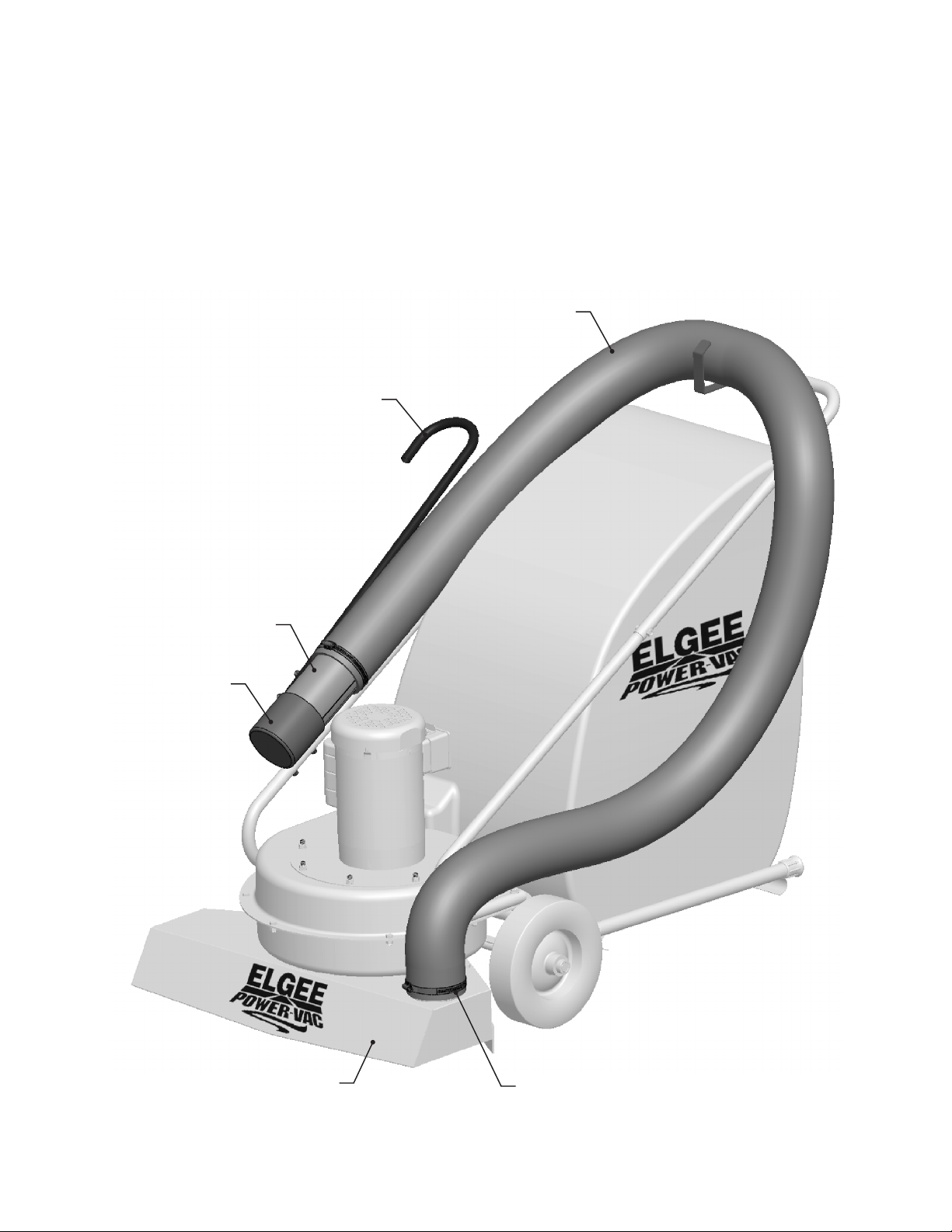
FILTER BAG
LEFT HANDLE LEG
MACHINE BODY
AND POWER PLANT
HANDLE
DOLLY
DEFLECTOR
RIGHT HANDLE LEG
3
• Ratchet wrench with 1/2” socket and extension
• 1/2” Open end wrench
• Rubber mallet
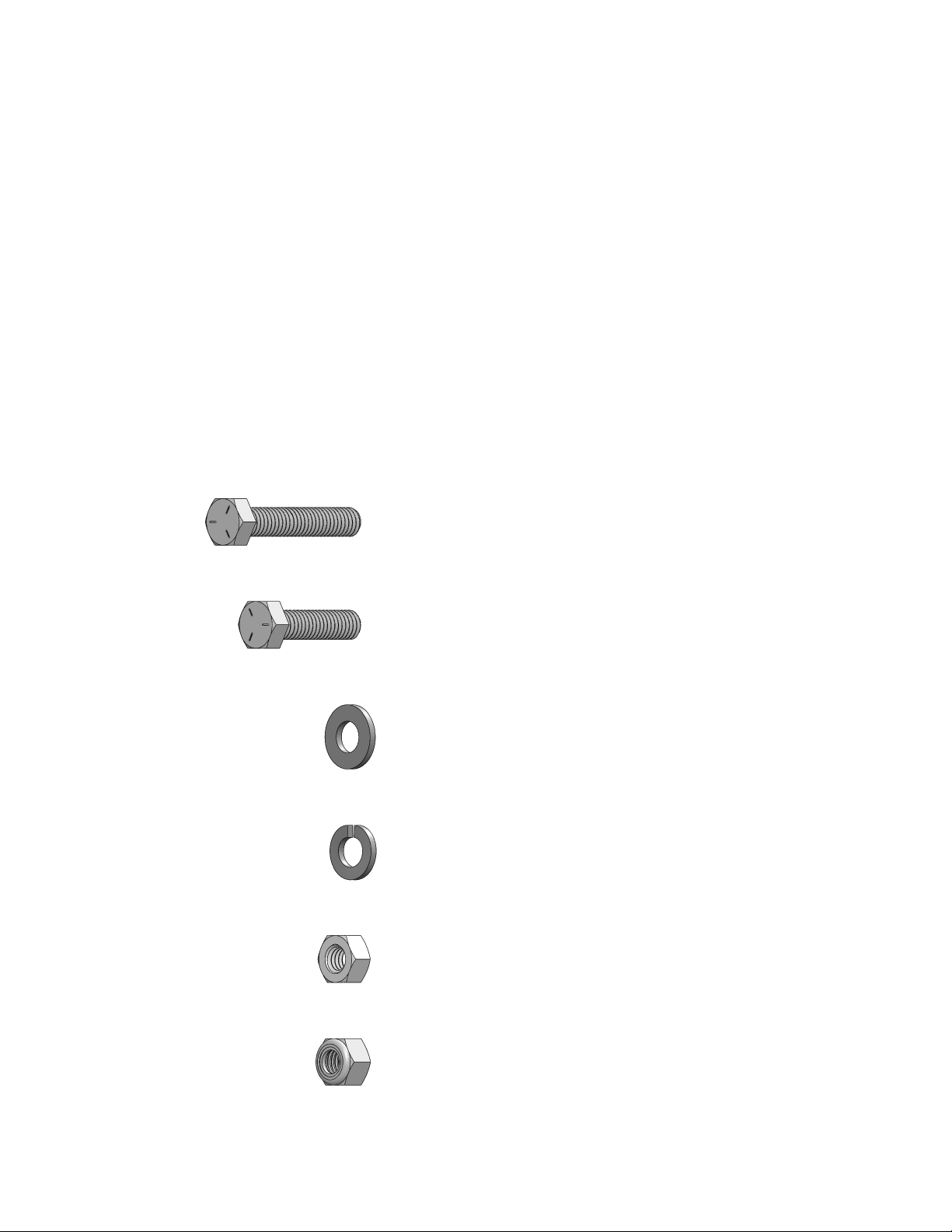
5/16” x 1-1/2” Hex Head Screw (4)
5/16” Locking Hex Nut (has an embed-
ded nylon ring on one side) (4)
5/16” Hex Nut (2)
5/16” Lock Washer (2)
5/16” Flat Washer (4)
5/16” x 1-1/4” Hex Head Screw (2)
4
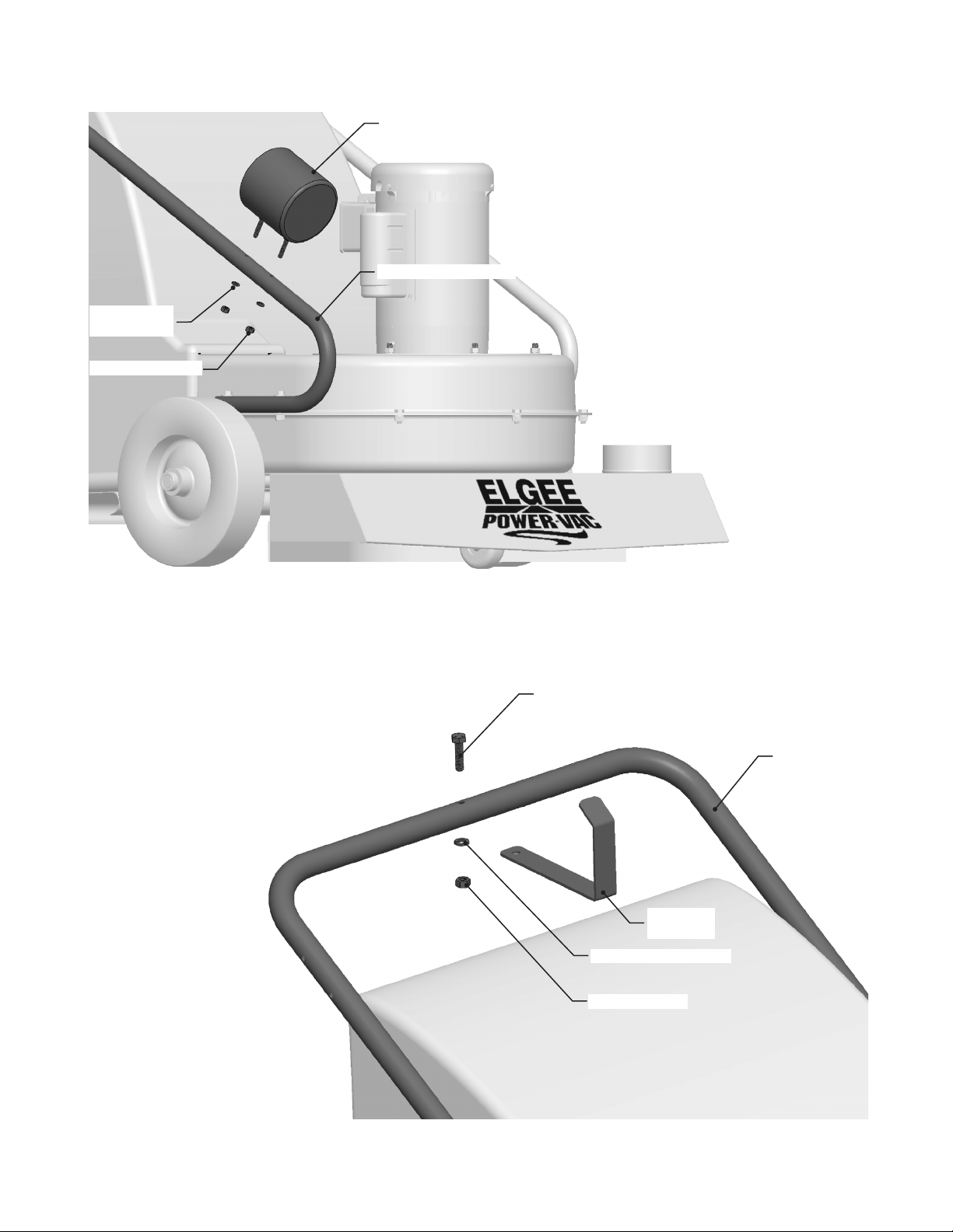
Aach the Le and Right Handle Legs to the machine body. NOTE: The Right Handle Leg has ve
holes and goes on the right side of the machine (when viewed from the operator’s posion); the
Le Handle Leg has only three holes and goes on the le side. For each leg, use two hex-head
machine screws, at washers, and locking hex nuts as shown in the illustraons below.
5/16” FLAT WASHER (2)
5/16” X 1-1/2” HEX
HEAD SCREW (2)
LEFT HANDLE LEG
(WHEEL NOT SHOWN FOR CLARITY)
5/16” LOCKING HEX NUT (2)
RIGHT HANDLE LEG
5/16” FLAT WASHER (2)
5/16” X 1-1/2” HEX
HEAD SCREW (2)
(WHEEL NOT SHOWN FOR CLARITY)
5/16” LOCKING HEX NUT (2)

5
LEFT HANDLE LEG
RIGHT HANDLE LEG
5/16” FLAT
WASHER (2)
5/16” X 1-1/4” HEX
HEAD SCREW (2)
5/16” HEX NUT (2)
HANDLE
Slide the Handle onto the Right and Le Handle Legs and
aach with two hex-head machine screws, at washers, and
hex nuts as shown in the illustraon. The two holes nearest
the bend must be on the right side of the machine when
viewed from the operator’s posion.
6
Line up the half hole of the Dolly with the machine’s Axle.
Strike the Dolly above the hole with a rubber mallet to snap it into place.
DOLLY
AXLE
WHEEL COLLAR
HALF HOLE ON DOLLY FRAME SNAPS
ONTO AXLE INBOARD OF WHEEL
COLLAR. STRIKE WITH RUBBER
MALLET TO FULLY ENGAGE.
(WHEEL NOT SHOWN FOR CLARITY)
7
Posion the Deector towards the inside of the machine so that its top and boom lips will engage
the channels on the discharge chute.
Use a rubber mallet to force the Deector outward unl it is centered on the discharge chute.
DISCHARGE CHUTE
TOP CHANNEL
ENGAGE THE DEFLECTOR’S
TOP LIP WITH THE TOP CHANNEL
DEFLECTOR
ENGAGE THE DEFLECTOR’S
BOTTOM LIP WITH THE
BOTTOM CHANNEL
BOTTOM CHANNEL
DEFLECTOR IN PLACE

8
Place the neck of the Filter Bag over the
Deector so that it covers the channels
on the machine’s discharge outlet.
Cinch the Filter Bag’s built-in
strap to secure its neck.
Loop each pair of the Filter Bag’s handle straps
around the Handle and fasten the metal clasps
to join them.

9
The next few pages describe the assembly, installaon, and use of the oponal Power-Vac Hose.
. Below is an exploded view showing the
parts included with the kit.
HOSE
BRACKET
HOSE NOZZLE
HOSE CUP
1/4” LOCK WASHER (2)
1/4” LOCK WASHER (3)
1/4” HEX NUT (2)
1/4” HEX NUT (3)
HEX HEAD MACHINE
SCREW, 1/4” x 1-1/4”
HEX HEAD MACHINE
SCREW, 1/4” x 1”
HOSE HANDLE
HOSE CLAMP (2)
5/16” HEX NUT
HOSE
5/16” LOCK WASHER
HEX HEAD MACHINE
SCREW, 5/16” X 1-1/4”
MANUAL HOSE
BAFFLE
10
HOSE CUP
RIGHT HANDLE LEG
HOSE
BRACKET
HEX HEAD MACHINE
SCREW, 5/16” x 1-1/4”
5/16” LOCK WASHER
5/16” HEX NUT
HANDLE
1/4” HEX NUT (2)
1/4” LOCK
WASHER (2)
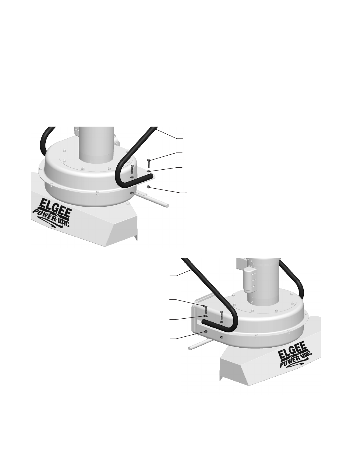
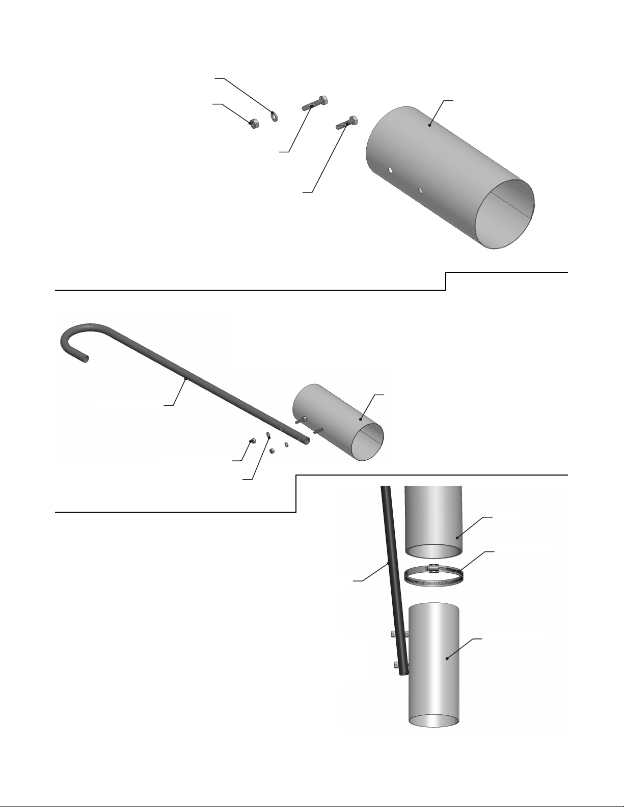
Aach the Hose Cup to the Right
Handle Leg with two 1/4” lock
washers and hex nuts.
Aach the Hose Bracket to the
Handle with a 5/16” x 1-1/4” hex
head machine screw, lock washer,
and hex nut. Note that the Bracket
goes on the underside of the Handle.
11
From the inside of the Hose Nozzle, pass a 1/4” x 1-1/4” hex head
machine screw through the hole nearest to one end of the Nozzle.
Secure the screw with a 1/4” lock washer and hex nut. Pass a 1/4” x
1” hex head machine screw through the other hole.
Posion the Hose Handle onto the two screws installed in Step
3 and secure with 1/4” lock washers and hex nuts. Some minor
distoron of the Hose Nozzle may occur as the fasteners are
ghtened. This is normal.
Slide a hose clamp onto the Hose. Push the Hose
onto the Hose Nozzle and ghten the hose clamp
to secure it.
HEX HEAD MACHINE
SCREW, 1/4” x 1-1/4”
HEX HEAD MACHINE
SCREW, 1/4” x 1”
HOSE NOZZLE
HOSE NOZZLE
HOSE NOZZLE
HOSE CLAMP
HOSE
1/4” LOCK WASHER
1/4” LOCK WASHER (2)
1/4” HEX NUT
HOSE HANDLE
HOSE HANDLE
1/4” HEX NUT (2)
12
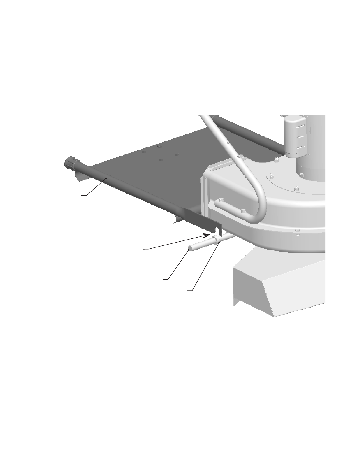
Insert the Hose Nozzle into the Hose Cup. Route the Hose over the machine as shown. Trim
the Hose to length so that it doesn’t drag on the ground or interfere with the machine’s
wheels. Slide a hose clamp over the free end of the Hose. Push the free end of the Hose
onto the port on the machine’s Inlet Housing and ghten the hose clamp to secure it.
HOSE NOZZLE
HOSE CLAMP
HOSE HANDLE
HOSE CUP
INLET HOUSING
HOSE
13
Your Power-Vac’s Hose (if so equipped) can be used with or without a Hose Bae, depending on
the type of lier or debris to be vacuumed. The Hose will have adequate sucon for most materi-
als without any baing. When maximum sucon is needed for heavy or dicult-to-pickup waste,
however, Elgee’s Hose Baes should be used. These divert all of the Power-Vac’s sucon to the hose
by blocking o the debris inlet within the Inlet Housing. A Manual Hose Bae is included with all
Hose kits unless the oponal Onboard Hose Bae is purchased. To use the Hose:
Turn on the motor.
Skip to Step 3 to use the Hose without any baing.
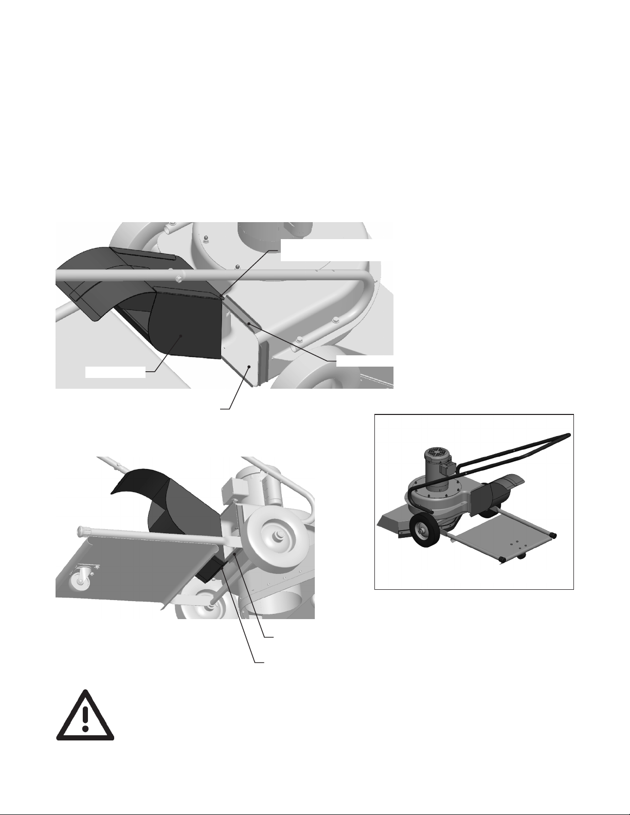
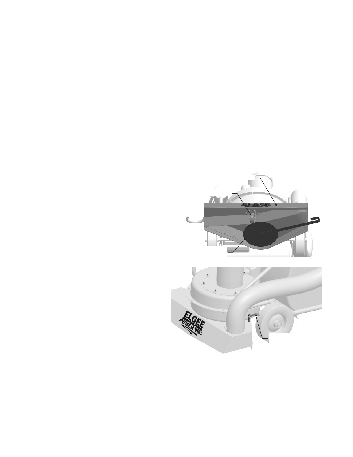
Slide the Manual Hose
Bae under the machine to the posion shown
below. This will prevent interference between
the Front Caster and the Manual Hose Bae’s
handle. When properly posioned, the Manual
Hose Bae’s disc will contact the rear of the
machine’s Inlet Housing. Skip to Step 3.
If your machine is
equipped with the oponal Onboard Hose
Bae, simply press down on the Bae
Control Handle to release the locking pin
and rotate it clockwise as far as it will go.
Note: Pull the machine backwards a few
inches before turning the Bae Control
Handle in order to ensure there will be no
interference with the Front Caster.
Grasp the Hose Handle; withdraw the Hose and the Hose Nozzle from the Hose Cup.
Pick up debris.
Reverse the above procedures to return to wide area vacuuming.
BAFFLE CONTROL
HANDLE
INLET HOUSING
MANUAL
HOSE BAFFLE
FRONT CASTER

14
Motor - Periodic lubricaon is necessary. Refer to the motor manufactur-
er’s literature for specic requirements.
Filter Bag - Elgee Filter Bags hold the debris picked up by your Power-Vac
and are designed to capture dust from the discharge air. To ensure
that your machine connues to operate at peak eciency:
• Shake the dust from the bag aer each use to maintain maximum
sucon. Do this several mes during the day if you’re picking up
mostly ne materials. Accumulated dust clogs the bag’s pores,
thereby reducing air ow and sucon.
• For outdoor use where dust control is not an issue, opening the
bag’s vent zipper will extend the maximum sucon me.
• Allow the bag to air dry if it becomes wet. A wet bag can rot or
allow the growth of mold and mildew.
• Launder the bag only if necessary. Use cold water and hang the
bag to air dry.
Your Elgee Power-Vac has been designed to provide years of trouble-free
service! Periodic aenon to the Motor and the Filter Bag is all that’s
needed to ensure that it always performs as well as when it was new.

15
www.elgee.com
Our website is full of helpful informaon and how-to videos.
Also visit our YouTube channel: www.youtube.com/user/ElgeePowerVac
[email protected]
We respond promptly to all email inquiries.
908-647-4100 or 800-742-0400
Call during normal business hours (8:30 am - 4:30 pm EST Monday
through Friday) to speak with a knowledgeable representave.
908-647-4242
Elgee Manufacturing Co., Inc.
225 Srling Road
Warren, NJ 07059

16
For ONE YEAR from date of installaon for the original purchases, Elgee will repair or
replace (at Elgee’s opon), FREE OF CHARGE, any parts or parts found upon examina-
on by the factory in Warren, New Jersey, or by any factory authorized center, to be
defecve in material and/or workmanship.
Except for bags, wiring, fuel tubes, cables, brass nipples, and rubber parts, Elgee
parts carry a ONE YEAR warranty against mechanical defects and workmanship.
Should defects become evident, parts must be returned, prepaid, to our factory for
inspecon. Elgee will not be responsible for repairs made outside of the factory
without authorizaon.
Charges for removal, reconnecon, shipping and/or transportaon of parts submit-
ted for replacement under this warranty must be borne by the purchaser.
Any changes or modicaon of this unit without the expressed wrien consent of
Elgee Manufacturing Co., Inc. will void this warranty.
Anything related to the conversion of an engine to propane fuel burning voids the
manufacturers warranty pertaining to any part directly associated with propane fuel
combuson. All other engine components carry full manufacturer’s warranty.
Engine warranty is carried by the manufacturer and their authorized dealers. Honda
engines carry a TWO YEAR warranty. Briggs & Straon oers a ONE YEAR warranty
on their Industrial/Commercial (I/C) engines and their 6HP Intek engines. Their war-
ranty for standard engines is 90 DAYS.
No warranty is expressed or implied. Elgee and any or all of its subcontractors shall
in any event NOT be liable for consequenal damages.
Implied warranes, including those of merchantability and tness for a parcu-
lar purpose, are limited to ONE YEAR from the date of purchase and to the extent
permied by law. Any and all implied warranes are excluded. This is the exclu-
sive remedy and liability for consequenal damages under any and all warranes.
Warranes are excluded to the extent exclusion is permied by law.
This manual suits for next models
5
Table of contents


