Elgo IMAX Series User manual

Operating Manual
SERIES IMAX
Magnetic, Self-Referencing Pseudo-Absolute Linear Encoder
Pseudo-absolute measurement by self-referencing
Resolution 1mm and repeat accuracy ±1 mm
Suitable for storage and conveyor technology
Long measuring distances up to 1048 m possible
CANopen standard (DS406 encoder profile)
or SSI (binary or Gray) interface
Robust housing for use in harsh environments
Wear-free and contactless measuring principle
Insensitive against dust, dirt and water
799000870 / Rev. 1 / 2019-05-09
Translation of the original operating manual


Contents
- 3 -
1Contents
1Contents ..................................................................................................... 3
2List of Figures............................................................................................. 4
3List of Tables .............................................................................................. 4
4General, Safety, Transport and Storage .................................................... 5
4.1 Information Operating Manual ........................................................................................... 5
4.2 Explanation of Symbols...................................................................................................... 5
4.3 Statement of Warranties..................................................................................................... 6
4.4 Demounting and Disposal.................................................................................................. 6
4.5 General Causes of Risk ..................................................................................................... 6
4.6 Personal Protective Equipment ............................................................................................ 6
4.7 Conventional Use ............................................................................................................. 7
4.8 Safety Instructions for Transport, Unpacking and Loading ....................................................... 7
4.9 Handling of Packaging Material.......................................................................................... 7
4.10 Inspection of Transport ...................................................................................................... 7
4.11 Storage ........................................................................................................................... 7
5Product Features ........................................................................................ 8
5.1 Functional Principle........................................................................................................... 8
5.2 Available Output Interfaces ................................................................................................ 8
6Technical Data ........................................................................................... 9
6.1 Identification .................................................................................................................... 9
6.2 Dimensions IMAX Sensor.................................................................................................... 9
6.3 Technical Data Sensor ..................................................................................................... 10
6.4 Technical Data Magnetic Tape ......................................................................................... 11
7Installation and First Start-Up ................................................................. 12
7.1 Operating Area .............................................................................................................. 12
7.2 Installation of the Magnetic Tape ...................................................................................... 13
7.3 Magnetic Tape Options BK80 / BK100.............................................................................. 16
7.4 Installation of the Sensor .................................................................................................. 17
7.5 Self-Referencing of the Measuring Range ........................................................................... 18
8Connections and Interfaces...................................................................... 19
8.1 CANopen Interface (CAO0) ............................................................................................. 19
8.2 SSI Interface (SSB0 and SSG0).......................................................................................... 20
9Disturbances, Maintenance, Cleaning ..................................................... 21
9.1 Fault Clearance.............................................................................................................. 21
9.2 Re-start after Fault Clearance ........................................................................................... 21
9.3 Maintenance .................................................................................................................. 21
9.4 Cleaning ....................................................................................................................... 21

Contents
- 4 -
10 Type Designation ..................................................................................... 22
10.1 Accessories .................................................................................................................... 23
11 Index ........................................................................................................ 27
2List of Figures
Figure 1: Single-track coding of the magnetic tape ...................................................................................... 8
Figure 2: Dimensions IMAX sensor ............................................................................................................. 9
Figure 3: Components of the magnetic tape ............................................................................................. 13
Figure 4: Magnetic tape handling ............................................................................................................ 14
Figure 5: Example BK80.......................................................................................................................... 16
Figure 6: Magnetic tape construction BK80............................................................................................... 16
Figure 7: Magnetic tape construction BK100............................................................................................. 16
Figure 8: Sensor alignment to the magnetic tape ....................................................................................... 17
Figure 9: Mounting tolerances of the sensor.............................................................................................. 18
Figure 10: CANopen interface................................................................................................................. 19
Figure 11: SSI - reading the data ............................................................................................................. 20
3List of Tables
Table 1: Resistance against Chemical Influence......................................................................................... 15
Table 2: Mounting tolerances .................................................................................................................. 18
Table 3: Connections CANopen - (open cable ends) ................................................................................. 19
Table 4: Connections SSI - (open cable ends) ........................................................................................... 20
Table 5: IMAX accessories ....................................................................................................................... 23

General, Safety, Transport and Storage
- 5 -
4General, Safety, Transport and Storage
4.1 Information Operating Manual
This manual contains important information regarding the handling of the device. For your own safety and operational safety, please ob-
serve all safety warnings and instructions. Precondition for safe operation is the compliance with the specified safety and handling instruc-
tions. Moreover, the existing local accident prevention regulations and the general safety rules at the site of operation have to be observed.
Please read the operating manual carefully before starting to work with the device! It is part of the product and should be kept close to the
device and accessible for the staff at any time. The illustrations in the manual are for better demonstration of the facts. They are not neces-
sarily to scale and can slightly differ from the actual design.
4.2 Explanation of Symbols
Special notes in this manual are characterized by symbols. The notes are introduced by signal words which express the magnitude of danger.
Please follow this advice and act carefully in order to avoid accidents, damage, and injuries.
Warning notes:
DANGER!
This symbol in connection with the signal word “Danger” indicates an immediate danger for the life and health of
persons. Failure to heed these instructions can result in serious damage to health and even fatal injury.
WARNING!
This symbol in connection with the word „Warning” means a possibly impending danger for the life and health of
persons. Failure to heed these instructions can result in serious damage to health and even fatal injury.
CAUTION!
This symbol in connection with the signal word “Caution” indicates a possibly dangerous situation. Failure to heed
these instructions can lead to minor injuries or damage of property.
Special safety instructions:
DANGER!
This symbol in connection with the signal word “Danger” indicates an immediate danger for the life and health of
persons due to voltage.
Failure to heed these instructions can result in serious damage to health and even fatal injury. The operations may
only be carried out by a professional electrician.
Tips and recommendations:
NOTE!
…points out useful tips and recommendations as well as information for an efficient and trouble-free operation.
Reference marks:
Marks a reference to another chapter of this manual.
Marks a reference to another chapter of another document.

General, Safety, Transport and Storage
- 6 -
4.3 Statement of Warranties
The producer guarantees the functional capability of the process engineering and the selected parameters.
4.4 Demounting and Disposal
Unless acceptance and disposal of returned goods are agreed upon, demount the device considering the safety instructions of this manual
and dispose it with respect to the environment.
Before demounting, disconnect the power supply and secure against re-start. Then disconnect the supply lines physically and discharge
remaining energy. Remove operational supplies and other material.
Disposal: Recycle the decomposed elements: Metal components in scrap metal, Electronic components in electronic scrap, Recycle plastic
components, dispose the remaining components according to their material consistence.
CAUTION!
Wrong disposal causes environmental damages!
Electronic scrap, electronic components, lubricants and other auxiliary materials are subject to special refuse and can
only be disposed by authorized specialists!
Local authorities and waste management facilities provide information about environmentally sound disposal.
Safety
CAUTION!
Please read the operating manual carefully, before using the device! Observe the installation instructions!
Only start up the device if you have understood the operating manual.
The operating company is obliged to take appropriate safety measure.
The initial operation may only be performed by qualified and trained staff.
Selection and installation of the devices as well as their embedding into the controlling system require qualified
knowledge of the applicable laws and normative requirements on the part of the machine manufacturer.
4.5 General Causes of Risk
This chapter gives an overview of all important safety aspects to guarantee an optimal protection of employees and a safe and trouble-free
operation. Non-observance of the instructions mentioned in this operating manual can result in hazardous situations.
4.6 Personal Protective Equipment
Employees have to wear protective clothing during the installation of the device to minimize danger of health.
Therefore:
Change into protective clothing before performing the works and wear them throughout the process.
Additionally observe the labels regarding protective clothing in the operating area.
Protective clothing:
PROTECTIVE CLOTHING
… is close-fitting working clothing with light tear strength, tight sleeves and without distant parts. It serves preliminari-
ly for protection against being gripped by flexible machine parts.
Do not wear rings, necklaces or other jewelry.
PROTECTIVE GLOVES
…for protecting the hands against abrasion, wear and other injury of the skin.
PROTECTIVE HELMET
…for protection against injuries of the head.

General, Safety, Transport and Storage
- 7 -
4.7 Conventional Use
The ELGO-device is only conceived for the conventional use described in this manual.
The ELGO linear encoder IMAX only serves to measure lengths and positions.
CAUTION!
Danger through non-conventional use!
Non-intended use and non-observance of this operating manual can lead to dangerous situations.
Therefore:
Only use the device as described
Strictly follow the instructions of this manual
Avoid in particular:
Remodeling, refitting or changing of the construction or single components with the intention to alter the
functionality or scope of the device.
Claims resulting from damages due to non-conventional use are not possible.
Only the operator is liable for damages caused by non-conventional use.
4.8 Safety Instructions for Transport, Unpacking and Loading
CAUTION!
Transport the package (box, palette etc.) professionally.
Do not throw, hit or fold it.
4.9 Handling of Packaging Material
Notes for proper disposal: 4.4
4.10 Inspection of Transport
Check the delivery immediately after the receipt for completeness and transport damage.
In case of externally recognizable transport damages:
Do not accept the delivery or only accept under reserve.
Note the extent of damages on the transportation documents or delivery note.
File complaint immediately.
NOTE!
Claim any damage immediately after recognizing it.
The claims for damage must be filed in the lawful reclaim periods.
4.11 Storage
Store the device only under the following conditions:
Do not store outside
Keep dry and dust-free
Do not expose to aggressive media
Protect from direct sun light
Avoid mechanical shocks
Storage temperature (6) needs to be observed
Relative humidity (6) must not be exceeded
Inspect packages regularly if stored for an extensive period of time (>3 months)

Product Features
- 8 -
5Product Features
The IMAX series is a Pseudo-absolute magnetic length measuring system. Pseudo-absolute means, that the ab-
solute code is recognized through a one-time movement of approx. 274 mm’s into an arbitrary direction after
power up. At this point the IMAX measures really absolute. Thus it is possible to guarantee an absolute meas-
urement over a total measuring length of 1048 m (CANopen) resp. 262 m (SSI) with a short sensor head length
of only 50 mm.
The sensors and the necessary evaluation electronics are integrated in a compact metal housing, which converts
the scanned signals into the desired interface format. By using the supplied adhesive tape, the absolutely coded
magnetic tape is glued onto a flat surface.
The maximum allowed mounting distance between IMAX sensor and magnetic tape is 1.8 mm.
Advantages:
Major advantages of the IMAX are its compact design and the high maximum measuring length. Further, the
system is equally suitable for retrofitting as well as new installations in existing machines and plants.
Essential features are:
Pseudo-absolute, self-referencing measurement
Compact design and high IP67 protection class
Contactless measuring principle
Resolution 1 mm (others on request)
Measuring length up to 1048 resp. 262 m
5.1 Functional Principle
The IMAX sensor is guided over a magnetic tape which is written with an absolute track. Due to automatic refer-
encing, the current position is detected by the sensor system after a movement of approx. 274 mm. The sensor
system scans the code sequence of the north and south poles and delivers a Pseudo-absolute value with a reso-
lution of 1 mm. The designation of the respective ELGO magnetic tape type depends on the output interface
used. For more information, refer to the technical data 6.3.
The measured value is processed by the internal evaluation electronics and is available either via a CANopen
interface (DS406 encoder profile) or SSI interface (binary or Gray code). From here the measured position can
be further processed by the subsequent electronics.
Figure 1: Single-track coding of the magnetic tape
5.2 Available Output Interfaces
Depending on the interface option ordered (see Type Designation 10), the sampled signal information is
converted by the internal evaluation electronics into one of the following output signals:
Interface option CAO0 CANopen standard interface according to DS406 (encoder profile)
Interface option SSB0 SSI interface, 25 bit (binary code)
Interface option SSG0 SSI interface, 25 bit (Gray code)
Further information can be found in chapter 8 Connections and Interfaces.
N S
NN S S N S NN N S S N SS S
S SS N N N SS

Technical Data
- 9 -
6Technical Data
6.1 Identification
The type label serves for the identification of the unit. It is located on the housing of the device and indicates the
exact type designation (= order reference 10) with the corresponding part number. Furthermore, the type
label contains a unique, traceable device number. When corresponding with ELGO please always indicate this
data.
6.2 Dimensions IMAX Sensor
Figure 2: Dimensions IMAX sensor

Technical Data
- 10 -
6.3 Technical Data Sensor
IMAX (standard version)
Mechanical Data
Measuring principle
Pseudo-absolute (self-referencing)
Repeat accuracy
±1 increment
System accuracy
in µm at 20° C
± (1250 + 50 x L)
L= measuring length in meters
Distance sensor - tape
max. 1.8 mm
Maximum measuring length
CANopen: 1048 m / SSI : 262 m
Housing material
ABS plastic
Dimensions
L x W x H = 50 x 12 x 25 mm
Magnetic tapes for CANopen:
AB20-80-10-1-R-17 (adhesive mounting, see section 7.2.4)
AB20-80-10-1-R-D-17-BK80 (rail mounting, see option 7.3.1)
AB20-80-20-1-R-D-17-BK100 (rail mounting, see option 7.3.2)
Magnetic tapes for SSI:
AB20-80-10-1-R-15 (adhesive mounting, see section 7.2.4)
AB20-80-10-1-R-D-15-BK80 (rail mounting, see option 7.3.1)
AB20-80-20-1-R-D-15-BK100 (rail mounting, see option 7.3.2)
Available magnetic tape lengths
see 6.4 Technical Data Magnetic Tape
Basic pole pitch
8mm
Sensor cable length
standard: 1.5 m (others on request)
Weight
approx. 40 g without cable; cable approx. 60 g/m
Electrical Data
Power supply voltage
10 … 30 VDC
Residual ripple
10 … 30 VDC <10 %
Current consumption
max. 150 mA
Available interfaces
CANopen standard (DS406) or SSI (binary or Gray) 10
Connections
standard: open cable ends
connectors optionally, see 10
Resolution
1 mm
Operating speed
max. 4.0 m/s
Environmental Conditions
Storage temperature
−25 … +85° C
Operation temperature
−10 … +70° C
−25 … +85° C (on request)
Humidity
max. 95 %, non-condensing
Protection Class
IP67

Technical Data
- 11 -
6.4 Technical Data Magnetic Tape
The magnetic tape consists of two components:
The actual magnetic tape which carries the position information
A mechanical stainless steel back iron
Magnetic Tape AB20-80-10-1-R-XX*
Coding
absolute, dual track system
Pole pitch
8 mm
Number of magnetic tracks
1
Number of bits CANopen
17 bit coding
Number of bits SSI
15 bit coding
Operation temperature installed
-20 °C …+65 °C
(-20°C … +80°C when using without adhesive tape, options „B“ or „D“)
Storage temperature uninstalled
Short-term: -10°C … +60°C
Medium-term: 0°…+40°C
Long-term: +18°C
(-20°C … +80°C when using without adhesive tape, options „B“ or „D“)
Gluing temperature:
+18°C … +30°C
Accurateness at 20°C
± (1000 + 50 x L) L= measuring length in meters
Material carrier tape
Precision Strip Steel 1.4310 / X10CrNi 18-8 (EN 10088-3)
Double-faced adhesive tape
3M-9088 (observe instructions), others on request
Width of the magnetic tape
10 mm
Height of the magnetic tape
with back iron, without adhesive tape: 1.35 mm (± 0.11)
with back iron + adhesive tape, without protective foil: 1.55 mm (± 0.13)
with back iron + adhesive tape + protective foil: 1.63 mm (± 0.14)
Height of the cover tape
without adhesive tape and protective foil: 0.20 mm (± 0.01)
with adhesive tape without protective foil: 0.40 mm (± 0.03)
with adhesive tape and protective foil: 0.48 mm (± 0.04)
Magnetic tape options
BK80 for rail mounting: see 7.3.1
BK100 for rail mounting: see 7.3.2
Length expansion coefficient
16 x 10-6 1/K
Thermal length expansion
∆L[m] = L[m] x [1/K] x ∆[K]
(L = tape length in meters, ∆= relative temperature change)
Bending radius
min. 150 mm (smaller on request)
Available lengths CANopen
Rolls up to max. 600 m (longer on request)
Available lengths SSI
Rolls up to max. 262 m
Weight magnetic tape
ca. 62 g/m (incl. magnetic tape and cover tape)
Tape imprint
ELGO standard, printing color black, digit height >= 5 mm
Relative humidity
max. 95 %, non-condensing
Protection class
IP65
Influence of external magnets
External magnetic fields must not exceed 64 mT (640 Oe; 52 kA/m) on
the surface of the magnetic tape as this could damage or destroy the code
on the tape.
Installation and First Start-Up
- 12 -
7Installation and First Start-Up
CAUTION
Please read the operating manual carefully before using the device! Strictly observe the
Installation instructions! In case of damage caused by failure to observe this operating
manual, the warranty expires.
ELGO is not liable for any secondary damage and for damage to persons, property or
assets.
The operator is obliged to take appropriate safety measures.
The first start-up may only be performed by qualified staff that has been trained and au-
thorized by the operator.
7.1 Operating Area
WARNING!
Do not use the device in explosive or corrosive environments! The device must not be in-
stalled close to sources of strong inductive or capacitive interference or strong electrostatic
fields!
CAUTION!
The electrical connections must be made by suitably qualified personnel in accordance with
local regulations.
The device may be designed for switchboard mounting. During work on the switchboard,
all components must be de-energized if there is a danger of touching the energized parts!
(protection against contacts)
Wiring works may only be performed in the de-energized state!
Thin cable strands have to be equipped with end sleeves!
Before switching on the device, connections and plug connectors have to be checked!
The device must be mounted in a way that it is protected against harmful environmental
influences such as splashing water, solvents, vibration, shock and severe pollution and the
operating temperature must not be exceeded.
Installation and First Start-Up
- 13 -
7.2 Installation of the Magnetic Tape
NOTE: External Magnetic Fields
The magnetic tape must not be influenced by external magnetic fields!
The magnetic tape must not come into direct contact with other magnetic fields (e.g. perma-
nent magnets, magnetic clamps, electromagnets, magnetic stands)! This may cause irrepara-
ble damage, which will compromise the measuring accuracy or even the functioning.
7.2.1 The Magnetic Tape
For IMAX with CANopen interface the absolute coded ELGO magnetic tape AB20-80-10-1-R-17 must be used,
while for versions with SSI interface the type AB20-80-10-1-R-15 is required. The two magnetic tape types only
differ in their coding (CANopen = 17 bit / SSI = 15 bit).
In the standard case, the magnetic tape is delivered as described below.
It is installed by gluing onto the respective mounting surface.
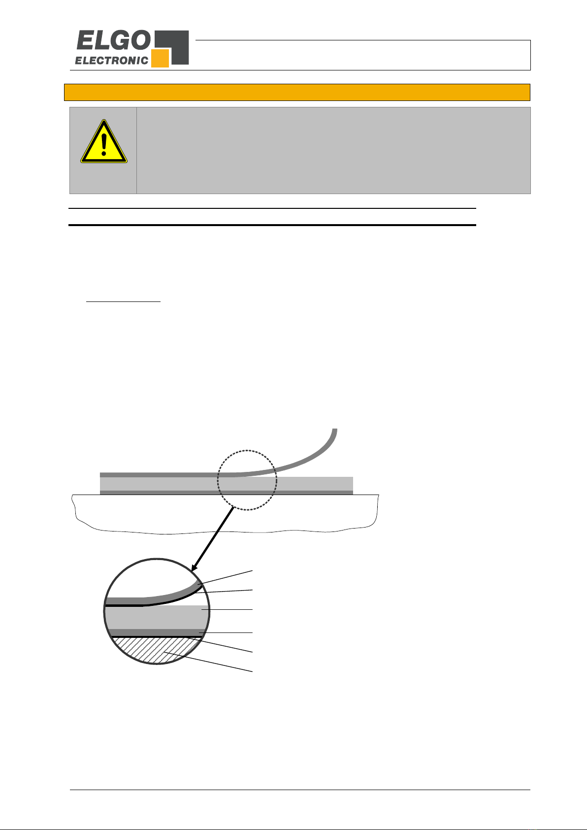
The magnetic tape consists of 2 pre-assembled components (see figure below):
A magnetized, flexible plastic tape (Pos. 3), which is connected with a magnetically conductive steel
tape as inference band (Pos. 4) and is supplied with an adhesive tape (Pos. 5).
A magnetized permeable cover tape (Pos. 1), which serves for the mechanical protection of the plastic
tape (not required for the measurement) and is supplied with an adhesive tape (Pos. 2).
Therefore a divergent tape structure and scope of delivery is also possible.
The cover tape is also available separately
Figure 3: Components of the magnetic tape
Pos. 1: Stainless steel cover tape
Pos. 2: Double-sided tape
Pos. 3: Magnetized plastic tape
Pos. 4: Carrier tape stainless steel
Pos. 5: Double-sided tape
Pos. 6: Mounting surface, for example machine bed

Installation and First Start-Up
- 14 -
7.2.2 Handling
In order to avoid tension in the tape, it must not be stretched, compressed or twisted. It should be stored with the
magnetized plastic tape to the outside. The minimum bending radius is 150 mm.
Figure 4: Magnetic tape handling
7.2.3 Processing hint for the gluing of magnetic tapes
Surface-Preparation: In order to guarantee optimal adhesion, all anti-adhesive contamination (e.g. oil, grease,
dust, separating agents) has to be removed using solvents with residue-free evaporation.
Suitable agents are ketones or alcohols. Typical solvents for cleaning the surface are a 50/50 isopropyl alco-
hol/water mixture or heptane. Those agents are offered by Loctite and 3M among others as surface cleaners.
When using solvents, always observe the manufacturer instructions! If the surface is copper, brass etc., it should
be sealed to avoid oxidation.
Contact-Pressure: The strength of the adhesion is directly dependent on the contact the adhesive can form with
the surface. Therefore it is important to use as much pressure as possible when gluing the tape, possibly by us-
ing aids such as draw rolls. The optimum contact pressure is 4…5 kg/cm2).
Gluing temperature: The optimal gluing temperature is between + 18° C and 30° C. Avoid colder sticking sur-
faces than + 10°C, because in this case the adhesive becomes too hard and perhaps a sufficient immediate
adhesion is hardly to achieve. After proper sticking, the stability of the connection is ensured also when the tem-
perature is below zero. The final tackiness of a sticking is from experience reached after approximately 72 hours
(at + 21° C). For gluing use only the supplied adhesive tape.
7.2.4 Cutting and Gluing
The magnetic tape is already cut to the required length at the factory.
NOTE!
When sticking the magnetic tape pay attention to the markings on the tape and the Sensor.
Improper installation does not provide the correct values. An already glued magnetic tape is
destroyed after the removal, and cannot be used again. Note also the direction of counting
of the measuring system
Preferably the magnetic tape should be glued close to an edge or into a groove, which
should be deep enough to embed the magnetic tape and the cover tape.
When unprotected, the cover tape may peel off!
Therefore: Use tape end caps (10.1) or let the cover tape overlap the end of the magnetic
tape and fix it with a screw.
The tape must be glued smoothly on the surface. The measuring accuracy decreases if the tape is not even!
Before gluing the magnetic tape and the cover tape onto the surface, they should be left lying on the mounting
surface for ca. 30 minutes so that the temperature matches. This prevents strain in the tape due to thermal ex-
pansion.
Magnetized
plastic tape
Steel tape

Installation and First Start-Up
- 15 -
Mounting steps:
1. Thoroughly clean the surface (7.2.3)
2. Acclimatization: let magnetic tape and cover tape adjust their temperature
3. Remove the protection foil from the magnetic tape
4. Glue magnetic tape under great pressure
5. Thoroughly clean surface of magnetic tape
6. Remove the protection foil from the cover tape
7. Glue the cover tape under great pressure
8. Safeguard the ends of the cover tape against peeling off, e.g. by using end caps (10.1)
7.2.1 Resistance against Chemical Influence
Table 1: Resistance against Chemical Influence
Show no or little effect in constant contact after 2-5 years:
formic acid
glycerol 93°C
linseed oil
soy beans oil
cotton seed oil
N-hexane
lactic acid
formaldehyde 40%
Iso octane
petroleum
Show weak to moderate effects in constant contact after approximately 1 year:
acetone
gasoline
acetic acid 30%
oleic acid
acetylene
steam
acetic acid, pure acetic acid
sea water
ammonia
acetic acid 20%
isopropyl ether
stearic acid 70°C, anhydrous
kerosene
Have strong effects when contacting permanently after 1-5 months:
benzene
nitric acid 70%
turpentine
toluene
lacquer solvent
nitric acid, red, vitriolic
carbon tetrachloride
tetrahydrofuran
trichloroethylene
nitrobenzene
hydrochloric acid 37%, 93°C
xylene

Installation and First Start-Up
- 16 -
7.3 Magnetic Tape Options BK80 / BK100
Especially in applications with long measuring lengths, it is not always possible to
bond the magnetic tape over the entire measuring distance. The options BK80 and
BK100 offer a remedy here, as these are assembled in such a way that they are
suitable for mounting in a profile rail. The magnetic tape is mounted here by
inserting it into the corresponding profile rail.
Two variants are available for rail mounting of the magnetic tape:
7.3.1 BK80
As shown in the following figure, the tape consists of a 8 mm wide magnetic tape which is connected to a
10 mm wide back iron stripe. The cover tape is not supplied with this variant.
Figure 6: Magnetic tape construction BK80
The exact ordering codes for the magnetic tapes can be found in section 10.1 Accessories.
7.3.2 BK100
As shown in the following figure, the tape consists of a 10 mm wide magnetic tape which is connected to a
20 mm wide back iron stripe. The cover tape is not supplied with this variant.
Figure 7: Magnetic tape construction BK100
The exact ordering codes for the magnetic tapes can be found in section 10.1 Accessories.
<SN XX/000000001/00000 MB20-80-10-1-R-D-1X-BK80 ELGO
10
8
1,35
Top view
Front view magnetized plastic tape
(magnetic tape)
magnetic conductive steel band
(back iron stripe)
BB
A
<SN XX/000000001/00000 MB20-80-20-1-R-D-1X-BK100 ELGO
20
10
1,35
Top view
Front view magnetized plastic tape
(magnetic tape)
B
A
magnetic conductive steel band
(back iron stripe)
Figure 5: Example BK80

Installation and First Start-Up
- 17 -
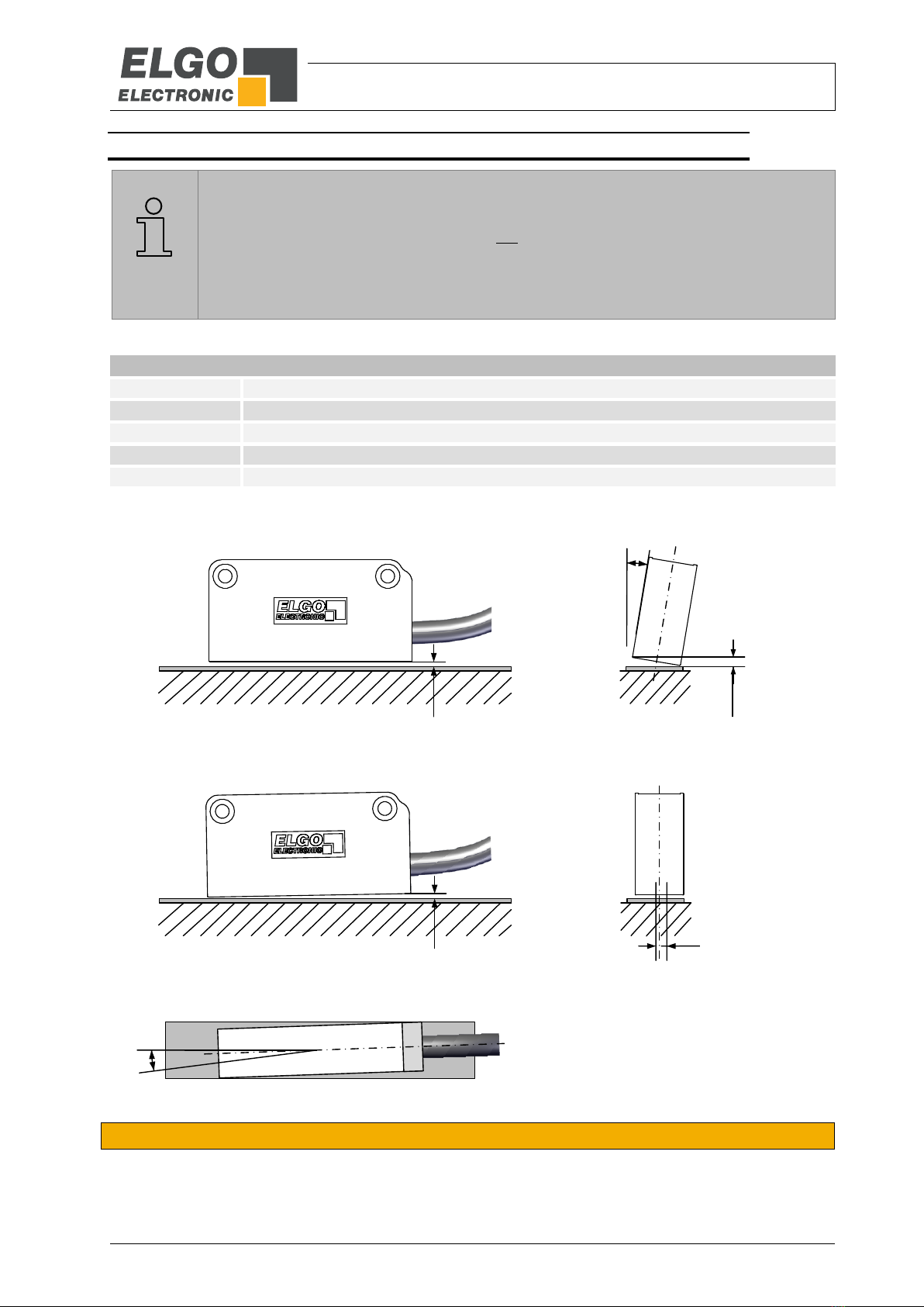
7.4 Installation of the Sensor
Fasten the sensor with two M3 cylinder head screws of suitable length (see 6.2). For absolute coded magnetic
tapes it is important that the sensor is mounted in the correct direction to the tape. Otherwise no measurement is
possible. Therefore the positive counting direction is indicated by arrows on the upper side of the magnetic tape.
7.4.1 Sensor Alignment to the Magnetic Tape
Figure 8: Sensor alignment to the magnetic tape
The cable outlet of the sensor points towards the positive counting direction.
The center of the sensor must be aligned with the center of the magnetic tape (see figure above).
More information about the mounting tolerances can be found in section 7.4.2.
UP
Cable outlet points towards the positive counting direction
Cable outlet Magnetic tape
MarkerMagnetic tape center = Sensor center ±1.0 mm
Installation and First Start-Up
- 18 -
7.4.2 Mounting Tolerances
REMARKS!
Ensure correct distance sensor / magnetic tape 0.1 mm ... max. 1.8 mm!
The LED on the sensor housing lights up red as soon as this distance is exceeded.
The cable outlet of the sensor points towards the counting direction (see section 7.4.1.)
Observe the specified tolerances when installing the system!
Outside these areas the function is not guaranteed!
Table 2: Mounting tolerances
Tolerances
Reading distance
max. 1.8 mm
Lateral angle
the maximum permissible reading distance must not be exceeded at any position
Pitch angle
the maximum permissible reading distance must not be exceeded at any position
Lateral offset
sensor center = magnetic tape center ±1.0 mm
Yaw angle
±0.5 °
Figure 9: Mounting tolerances of the sensor
7.5 Self-Referencing of the Measuring Range
During movement, the IMAX first determines its starting from the switch-on position. After a moving distance of
approx. 274 mm, the IMAX has collected all necessary information to determine the absolute position.
Reading Distance
Pitch Angle
Yaw Angle
±0.5 °
Lateral Angle
Lateral Offset
±1.0 mm
max. 1.8 mm
max. 1.8 mm
max. 1.8 mm

Connections and Interfaces
- 19 -
8Connections and Interfaces
8.1 CANopen Interface (CAO0)
When ordering the CA0 interface option, the IMAX measuring system is equipped with a CAN interface accord-
ing to CANopen standard DS406 for encoder device profiles.
The CAN interface is terminated internally with a 120 Ωterminating resistor as standard. If no internal termina-
tion is required, the additional option "A" must be specified with the order (10).
In order to start the communication with the IMAX an NMT command has to be sent first.
The following identifiers are given:
CAN - Identifier
(6 Byte telegram)
181 (16) = Identifier
First 4 bytes = Position (resolution 1 mm), Bit rate = 125 KB/s*
Next 2 bytes = Speed in mm/s
Heart Beat = OFF
Node-ID = 0x04
Event-Timer 1st TPDO = 5 ms
Figure 10: CANopen interface
*) The bit rate and other parameters can be changed via CAN interface.
8.1.1 Connections CAN Interface
Table 3: Connections CANopen - (open cable ends)
Connection Type
Drawing
Color
Function
Description
Open cable ends
black
0 V / GND
Ground
brown
+VCC
10 … 30 VDC
yellow
CAN HIGH
positive CAN signal
green
CAN LOW
negated CAN signal
blank
Shield
CAN shielding
Position Speed
LSB MSB LSB MSB

Connections and Interfaces
- 20 -
8.2 SSI Interface (SSB0 and SSG0)
Principle of the function: If the clock is not interrupted for the time Tm-T/2 (output of further 25 periods), the shift
register clocks once again the same data value (error recognition in evaluation). With the SSI interface, trans-
mission frequencies up to max. 250 KHz can be ensured. The SSI interface is generally terminated with an inter-
nal terminating resistor.
Some encoders contain a Power Failure Bit (PFB):
With IMAX the PFB is always „low“, unless the maximum allowed distance from sensor to tape is exceeded.
Figure 11: SSI - reading the data
The data format of the SSI interface depends on the respective order designation in the type code (10):
SSB0 = binary code
SSG0 = Gray code
8.2.1 Connections SSI Interface
Table 4: Connections SSI - (open cable ends)
Connection Type
Drawing
Color
Function
Description
Open cable ends
black
0 V / GND
Ground
brown
+VCC
10 … 30 VDC
green
SSI_DATA+
positive SSI-DATA signal
yellow
SSI_DATA−
negated SSI-DATA signal
red
SSI_CLK+
positive SSI-CLOCK signal
orange
SSI_CKL−
negated SSI-CLOCK signal
blank
Shield
Shielding
T
Tm-T/2
1 1 G23 G22 G21 G20 G19 G18 G17 G16 G15 G14 G13 G12 G11 G10 G9 G8 G7 G6 G5 G4 G3 G2 G1 G0 PFB 0 1
1 2 3 4 5 6 7 8 9 10 11 12 13 14 15 16 17 18 19 20 21 22 23 24 25
Non-inverted SSI-Clock
+ 1 Power Failure Bit
24 Bit
PFB = Power failure bit
T = Cycle duration of the clock signal
TM = Monoflop time >15 µs
Not inverted SSI Clock
Table of contents
Other Elgo Media Converter manuals

Popular Media Converter manuals by other brands

Actox
Actox ABE12KX user manual

Siemens
Siemens MICROMASTER 4 installation instructions

Broadway Limited
Broadway Limited Paragon 3 Reference manual

TR-Electronic
TR-Electronic CD-75 Series technical information

HEIDENHAIN
HEIDENHAIN LC 2 1 Series Replacing Instructions

Advantech
Advantech USB-4600 Series user manual


 user guide")
