elinvision iQube VAS-41 User manual

002-UG-0001-R03Page 1
3D Foot Scanner
Model iQube VAS-41
Installation and User Guide

002-UG-0001-R03Page 2
© 2023 UAB Elinvision
Information in this guide is subject to change without notice.
No part of this document may be reproduced or transmitted in any way without the express written
permission of UAB Elinvision.
Registered trademarks are the property of their respective owners.

002-UG-0001-R03Page 3
TABLE OF CONTENTS
TABLE OF CONTENTS ...............................................................................................3
1. Introduction ......................................................................................................4
1.1. About this guide......................................................................................................................... 4
1.2. Contact information................................................................................................................... 4
1.3. Product description....................................................................................................................... 5
1.4. Product overview ....................................................................................................................... 6
1.4.1. Model iQube VAS-41.............................................................................................................. 6
2. General information.......................................................................................................................... 8
2.1. Symbols ...................................................................................................................................... 8
2.2. System requirements................................................................................................................. 9
2.3. General safety information........................................................................................................ 9
2.4. Laser safety ................................................................................................................................ 9
2.5. Care of the 3D Foot Scanner................................................................................................... 10
2.6. Calibration and repair.............................................................................................................. 10
2.7. Limited warranty terms and conditions................................................................................. 10
2.8. European Union (EU) customer information......................................................................... 11
3. Unpacking and installation..................................................................................12
4. Software installation............................................................................................13
5. Connecting the scanner ................................................................................................................. 13
6. Start the software............................................................................................................................ 14
7. Your first measurement.................................................................................................................. 14
8. Software user guide........................................................................................................................ 15
9. System specifications model iQube VAS-41................................................................................ 16
10. Appendices.................................................................................................................................... 18
10.1. Troubleshooting......................................................................................................................... 18
10.2. REACH compliance statement ................................................................................................. 18

002-UG-0001-R03Page 4
1. Introduction
1.1. About this guide
Congratulations on your new purchase. The 3D Foot Scanner is intended to obtain foot dimensions for
shoe size measurement and selection.
This guide will assist you with the installation and usage of the 3D Foot Scanner model iQube VAS-41.
The installation consists of:
✓Unpacking & installation
✓Software installation
✓Connecting the scanner
✓Starting the software
✓Your first measurement
Enjoy your 3D Foot Scanner.
1.2. Contact information
UAB Elinvision
Terminalo str. 3
Biruliskiu village, Karmelava
Kaunas district
54469 Lithuania
Tel. +370 37 210078
Fax. +370 37 452780
Website: http://www.elinvision.com/
Sales: sales@elinvision.com
Support: [email protected]om

002-UG-0001-R03Page 5
1.3. Product description
The 3D Foot Scanner uses laser triangulation technology
combined with 2D color images for a precise 3D
representation of the feet.
Cameras plus line lasers are used to capture the 3D image
and texture. This allows precise and fast scans of feet in
normal ambient light conditions.
The laser projects a line onto the foot. The camera captures
the laser projection.
The laser and camera are mounted on a moving carriage.
Geometric algorithms are used to measure and digitize the
surface. The processing of the 3D and 2D images,
calculations, measurements and interpretation of the results is
done by the software package on the connected PC.

002-UG-0001-R03Page 6
1.4. Product overview
1.4.1. Model iQube VAS-41
The 3D Foot Scanner model iQube VAS-41
package includes:
•iQube 3D Foot Scanner.
•Scanner cover / side support step.
•USB cable A-B 1.8m (71 Inches). Do not
use any other USB cable!
•Power cord with a C13 plug, the other side
will be country specific.
•Foambox lifters.
•This guide.
•Transportation lock.

002-UG-0001-R03Page 7
•Vacuum suction cup to lift the glass plate to
remove the transportation lock.
•Unpacking instructions.
•Optional foot switch / pedal.
002-UG-0001-R03Page 8
2. General information
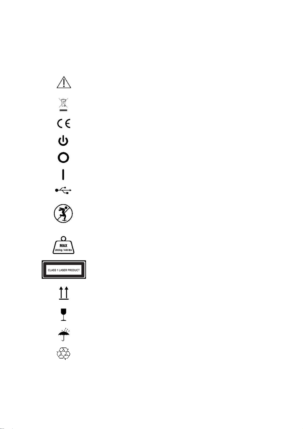
2.1. Symbols
The following symbols may appear on the product, packaging or documentation:
Caution, read these instructions carefully.
If used on the product label: Caution, consult accompanying documentation.
Regulatory Mark for the European Directive 2002/96/EC on Waste Electrical
and Electronic Equipment (WEEE).
CE mark according to the applicable European Directives.
Power
Power off
Power on
USB port
Do not jump on the glass plate, or tread lightly.
Do not exceed the maximum weight limit of 200Kg (440 lbs).
Class 1 laser product as per IEC 60825-1:2014 (Third Edition).
This way up.
Fragile, handle with care.
Keep dry.
Recyclable packaging.

002-UG-0001-R03Page 9
2.2. System requirements
Refer to the Installation Guide and User Manual for the software.
2.3. General safety information
This section contains instructions regarding safety. Please read carefully.
•Prior to a measurement session, instruct the client how to stand on the 3D Foot Scanner. The
client should only step or stand on the designated scan area or center of the support step.
•Do not jump on the glass plate. Protect the glass plate from high impacts or sharp objects.
•Do not exceed the maximum specified weight of 200 Kg (440 lbs.).
•Do not use the 3D Foot Scanner if cables or parts such as the glass plate or side support step
are damaged.
•Do not use a USB connection cable longer than the supplied 1.8m (71 Inches) cable, use a
powered hub or active extension cable in combination with the supplied cable if a longer
connection cable is required.
•Always use the supplied USB cable for compliance to the applied standards.
•Install the 3D Foot Scanner level on a solid and non-skid surface.
•Power off the 3D Foot Scanner when not in use or before connecting / disconnecting cables.
•When powered off, wait at least 10 seconds before powering up again.
•Unplug the power cord when not in use for longer periods.
•When unplugging the power or USB cable, always pull the plug, never the cable.
•Protect the 3D Foot Scanner cables and connectors from accidental damage. Secure the
cables to prevent accidental tripping or entanglement. Do not bend, twist, stretch, modify or
wrap the cables.
•Protect the 3D Foot Scanner from shocks and vibration. Reinstall the shipping lock when
transporting.
•Do not place the 3D Foot Scanner adjacent to equipment or power lines which generate strong
electromagnetic or electrostatic fields, or in the vicinity of sensitive equipment. Relocate if
necessary.
•Do not operate or store the 3D Foot Scanner outside the specified environmental temperature
and humidity range, do not expose to direct sunlight, do not expose to moisture. For indoor
use only.
•Replace the fuse with one of the same rating, unplug the power cord before replacing the fuse.
2.4. Laser safety
•The 3D Foot Scanner uses Class 1 laser light, do not stare into the laser beam or view directly
with optical instruments. Laser light can damage your eyes.
•The 3D Foot Scanner is classified per EN 60825-1:2014 as a Class 1 laser product.
•The 3D Foot Scanner complies with FDA performance standards for laser products except for
deviations pursuant to Laser Notice No. 50, dated June 24, 2007.

002-UG-0001-R03Page 10
2.5. Care of the 3D Foot Scanner
•To ensure client safety, clean and, if applicable, disinfect the glass plate between uses.
•The glass plate and other surfaces can be cleaned and disinfected with a suitable disinfectant
or a mild detergent (for example Dettol, Washing up liquid), or the supplied wipes.
•Do not pour or spray the cleaning or disinfectant product directly on the 3D Foot Scanner or
glass plate, use a damp cloth or lint free wipe to clean and remove contamination.
•Make sure the glass plate is completely dry before use.
•Do not use solvent based, flammable, aggressive or abrasive cleaning or disinfectant products
(such as acetone, or ammoniac). Consult the labelling of the products before use.
2.6. Calibration and repair
•The 3D Foot Scanner is calibrated in the factory. A new calibration is required after replacing
the laser, optics, camera or other mechanical parts by a qualified and authorized technician or
in case these parts are out of alignment due to mishandling, shocks or heavy vibrations.
•There are no user serviceable parts inside the 3D Foot Scanner. Disassembly will void
warranty.
•The only user replaceable part, apart from the cables, is the fuse, it is located next to the
power switch on the back panel.
•Repairing the 3D Foot Scanner should only be performed by qualified and authorized
personnel. Contact the support department for more information.
•Save the original packaging, it can be used to ship the 3D Foot Scanner for repair.
2.7. Limited warranty terms and conditions
•The 3D Foot Scanner (the “Product”) is warranted against defects in materials and
workmanship for a period of one (1) year from the date of the original purchase (the "Warranty
Period") when used in accordance with the Installation and User Guide.
•If the Product is determined to be defective during the Warranty Period, UAB Elinvision will at
its option (1) repair the Product, (2) exchange the Product with a new Product or refurbished
Product that is equivalent to new in performance and reliability.
•Repair or exchange as provided under this warranty is the sole and exclusive remedy
of the consumer and UAB Elinvision’s sole and exclusive liability in respect of defects in
the Product.
•Customer shall contact the UAB Elinvision support department to initiate the warranty service
procedure. Customer shall exhaust all support options before doing so.
•Replacement parts or Product will be covered by a 90 days warranty or the remainder of the
Product Warranty Period, whichever period is longer. The Product Warranty Period will not be
extended.
•Replaced parts or Product will become the property of UAB Elinvision.
•To the extent permitted by applicable law(s) UAB Elinvision does not assume any liability for
loss of or damage to or corruption of data, for any loss of profit, loss of use of products or
functionality, loss of business, loss of contracts, loss of revenues or loss of anticipated
savings, increased costs or expenses or for any indirect loss or damage, consequential loss or
damage or special loss or damage.
•This Limited Warranty does not affect your legal (statutory) rights under your applicable
national laws relating to the sale of products.

002-UG-0001-R03Page 11
The warranty includes:
•The cost of all parts and labor in the repair or replacement of the Product, following
mechanical or electrical breakdown, which are shown to the satisfaction of UAB Elinvision to
be defective due to faulty materials or workmanship.
The warranty excludes:
•Normal wear and tear, including wearing parts.
•Damage to the glass plate.
•Failures due to accidental damage, careless operating, unintended use, use or incorrect
installation of incompatible third party equipment, negligence, handling damage, transit
damage, misuse, non-compliance with the supplied instructions, force majeure, natural forces
or damage due to other external causes.
•Unsatisfactory performance caused by non-compliance with the minimum system
requirements, the use or attachment of any accessories not produced or authorized by UAB
Elinvision.
•Repairs, alterations or disassembly carried out by unauthorized parties.
•Products damaged during transit to UAB Elinvision due to insufficient or improper packaging.
•Software (refer to the End User License Agreements of the supplied software).
2.8. European Union (EU) customer information
•The 3D Foot Scanner is marked according to the European directive 2002/96/EC on
Waste Electrical and Electronic Equipment (WEEE).
•This symbol on the product or the documentation indicates that this product may
not be treated as household waste. Instead it shall be handed over to the
applicable collection point for the recycling of electrical and electronic equipment.
Disposal must be carried out in accordance with local environmental regulations
for waste disposal. For more detailed information about disposal of this product,
please contact the distributor where you purchased the product, your household
waste disposal service or your local city office.
•Alternatively, the product can be send back to UAB Elinvision for disposal or trade-in.
Contact the support department for details.
002-UG-0001-R03Page 12
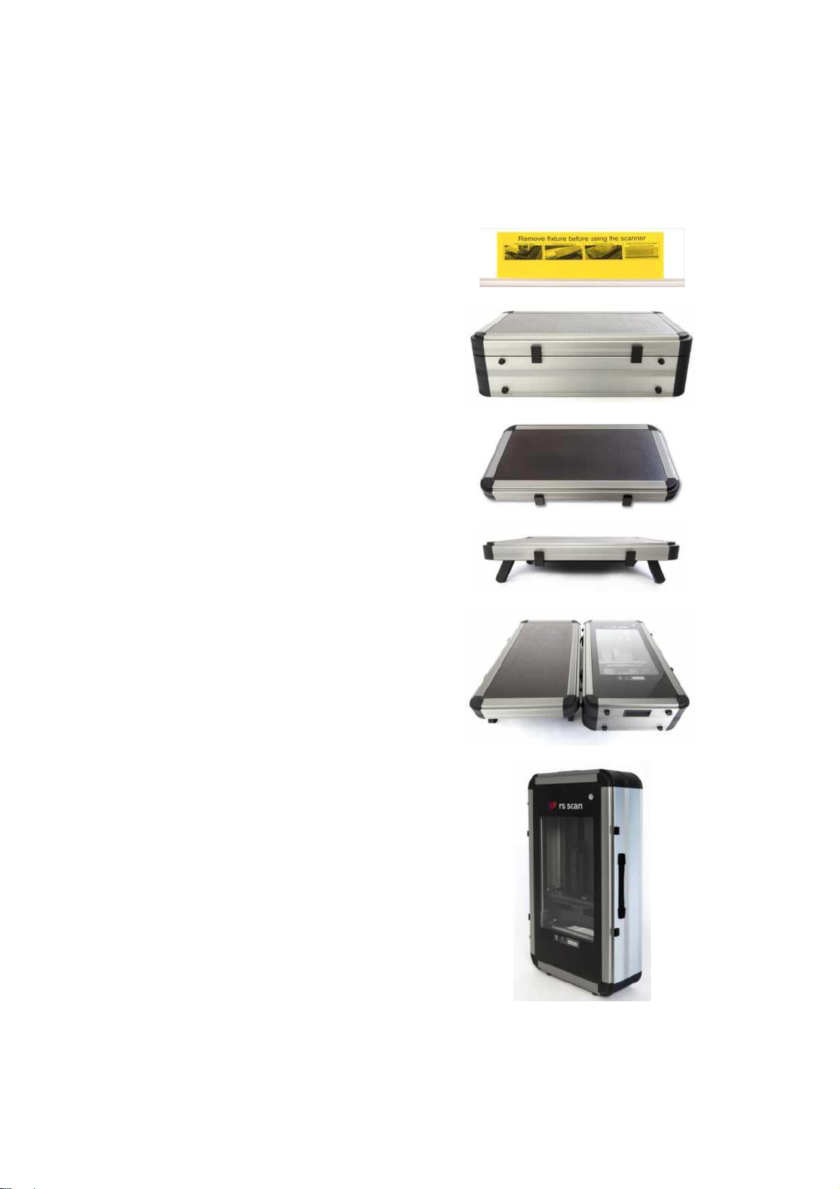
3. Unpacking and installation
The scanner is shipped with a transportation lock,
follow the instructions on the lock to remove it.
Place the scanner at the point of use.
Place the scanner level on a solid flat surface. Do
not place under direct lighting or sunlight. Unlock
the clips from the scanner cover.
Remove the cover.
Unfold the support legs to transform the cover into
the support step.
Place the support step next to the scanner for
measurements in full weight bearing conditions.
Note: the support step can be placed underneath
the scanner with the front set of legs folded to
allow measurements to be taken with a seated
subject under partially weight bearing condition.
The scanner can be set vertical for measurement
in a non-weight bearing condition.

002-UG-0001-R03Page 13
4. Software installation
Caution: Do not connect the 3D Foot Scanner to the USB port of
the PC until the software is installed.
Refer to the Installation Guide and User Manual for the installation of the software.
5. Connecting the scanner
Once the software has been successfully installed,
you are ready to connect the 3D Foot Scanner.
Verify if the power switch is in the OFF position
(Marked O).
Connect the power cord to the 3D Foot Scanner and
plug it into a properly grounded AC outlet.
Connect the 3D Foot Scanner to your PC using the
supplied USB cable. Connect the USB-B plug side of
the cable (square plug) to the USB connector on the
3D Foot Scanner.
Match the orientation of the plug and connector, align
the beveled edges of the plug with the beveled edges
of the connector.
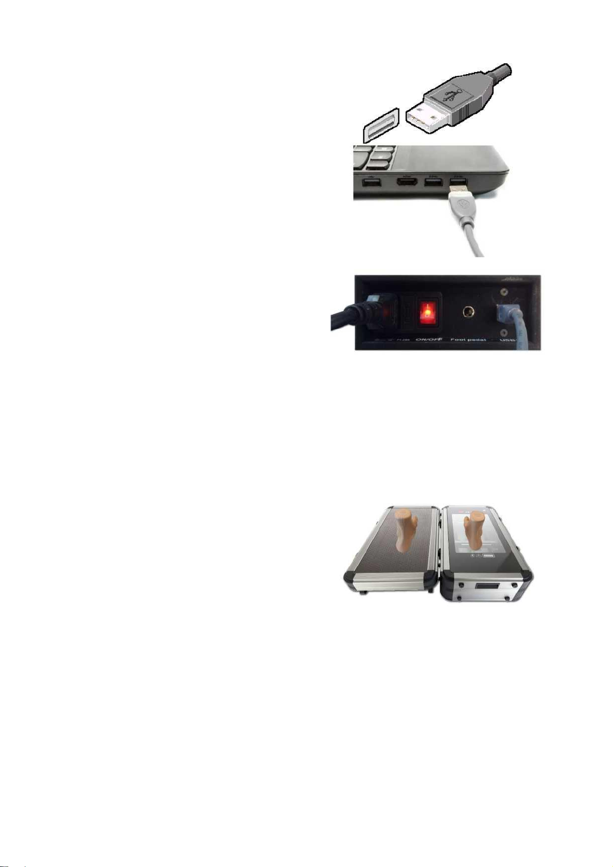
002-UG-0001-R03Page 14
Connect the USB-A plug side of the cable (flat
rectangular plug) to a free USB port on your PC.
Match the orientation of plug and connector.
When the hardware setup is completed, switch on the
3D Foot Scanner by switching the power switch to the
ON position (Marked I).
A self-test will be performed, after that the 3D Foot
Scanner is ready for use.
The scanner button on the top will lit green when the
scanner is ready.
6. Start the software
Refer to the Installation Guide and User Manual for the software.
7. Your first measurement
Once you have installed the software and set up the 3D Foot Scanner, you are ready to take your first
measurement.
Let the client step carefully onto the glass plate of the
scanner with either left or right foot, the other foot on
the support step.

002-UG-0001-R03Page 15
Roughly position the center of the foot in the center of
the transparent part of the glass to obtain the best scan
result.
Refer to the Installation Guide and User Manual for the software for further instructions on how to take
a measurement.
8. Software user guide
Refer to the Installation Guide and User Manual for the software.

002-UG-0001-R03Page 16
700 x 380 x 199 mm (27.55 x
14.96 x 7.83 Inches)
17 Kg (37.48 lbs.)
330 x 180 x 150 mm ±5 mm
(13 x 7 x 6 Inches ±0.2 Inches)
+-0.4mm (0.157 Inches)
6 seconds
Relative humidity:
Maximum 80% non-condensing
9. System specifications model iQube VAS-41
Dimensions (with cover) (L x W x H):
Weight:
Scanning area (L x W x H):
Accuracy:
Scan time:
Radiation output and standards information:
Laser class: 2 lasers Class I
Max output of laser radiation: 1.5 mW
Emitted wavelength(s): 650nm
Standard(s): IEC 60825-1:2014 (Second Edition)
Camera type:
Operating temperature range:
Storage temperature range:
4 monochrome cameras: 1/3 inch
752x480 CMOS
1 color camera: 1/3 inch 752x480
CMOS RGB filter
+10 °C .. +30 °C (+50 °F .. +86 °F)
+5 °C .. +50 °C (+41 °F .. +122 °F)

002-UG-0001-R03Page 17
I/O:
1 Mains connection:
2 Fuse:
3 Power switch:
4 Foot pedal:
5 USB:
1x USB 2.0 (1.8m USB cable A-B)
Supply voltage:
Power consumption: 100 V - 240 V AC 50-60 Hz
9 W non scanning
19 W scanning
connect to the AC mains
mains fuse, replace with same rating (1.25A)
to switch the 3D Foot Scanner on or off, lights red when power is on and mains
connected
to connect the optional foot pedal, can be used to start a measurement
connect the USB-B end of the USB cable, connect the USB-A end of the USB
cable to the PC
1 Start button / Touch, cover or wave over at a short distance to start a measurement.
status LED:
A green light indicates the scanner is ready, a red light indicates the scanner is
busy.

002-UG-0001-R03Page 18
10. Appendices
10.1. Troubleshooting
The power switch light does not light up
✓Check if the power switch is in the ‘on’ position (marked I).
✓Check if the power cord is plugged in to the AC outlet.
✓Check the fuse.
The PC does not recognize the scanner
✓Check if the USB cable is plugged in at the scanner and the PC.
✓Reinstall the software.
10.2. REACH compliance statement
The European Union chemical regulation 2006/1907/EEC: REACH (Registration, Evaluation,
Authorization and Restriction of Chemicals), entered into force on 1st June 2007.
As a manufacturer of articles (products), according to article 33, UAB Elinvision is obligated
to provide the recipient or consumer of its products, containing any of the Substances of Very
High Concern (SVHC) of the published candidate list in a concentration above 0.1% w/w,
with sufficient information to allow safe use of the product including, as a minimum, the name
of that substance.
All information in this statement is based on our current knowledge. We take neither liability
nor warranty for factors beyond our knowledge and control.
The majority of products supplied by UAB Elinvision do not contain any of the Substances of
Very High Concern (SVHC) of the published candidate list in a concentration above 0.1%
w/w. The articles listed below may contain a Substance of Very High Concern (SVHC) of the
published candidate list in a concentration above this threshold.
Article
Substance
CAS number
Application
Power cables, USB cables.
Bis (2-ethyl(hexyl)phthalate)
(DEHP)
117-81-7
Plasticizer in PVC
cables.
Table of contents
Other elinvision Scanner manuals


