logo
Brands
  1. Home
  2. •
  3. Brands
  4. •
  5. Elkay
  6. •
  7. Refrigerator
  8. •
  9. Elkay ECU8*1A User manual

Elkay ECU8*1A User manual

This manual suits for next models

2

Other Elkay Refrigerator manuals

Elkay ECH8 Installation manual

Elkay

Elkay ECH8 Installation manual

Elkay ECP8 Installation manual

Elkay

Elkay ECP8 Installation manual

Elkay ECH8 2MQ Series Installation manual

Elkay

Elkay ECH8 2MQ Series Installation manual

Elkay ECH8-1 Installation manual

Elkay

Elkay ECH8-1 Installation manual

Elkay ECH8-1E Installation manual

Elkay

Elkay ECH8-1E Installation manual

Elkay ECH8 2MQ Series Installation manual

Elkay

Elkay ECH8 2MQ Series Installation manual

Elkay EFRC8C-A Installation manual

Elkay

Elkay EFRC8C-A Installation manual

Elkay ERS1-2F Installation manual

Elkay

Elkay ERS1-2F Installation manual

Elkay ERW20-1B User manual

Elkay

Elkay ERW20-1B User manual

Elkay ECP8-1 User manual

Elkay

Elkay ECP8-1 User manual

Elkay EZ8WS Series User manual

Elkay

Elkay EZ8WS Series User manual

Elkay ER30 User manual

Elkay

Elkay ER30 User manual

Elkay ECH8GRN Installation manual

Elkay

Elkay ECH8GRN Installation manual

Elkay ECU8 1E Series Installation manual

Elkay

Elkay ECU8 1E Series Installation manual

Elkay ERS1-1D Installation manual

Elkay

Elkay ERS1-1D Installation manual

Elkay ECU8 1G Series Installation manual

Elkay

Elkay ECU8 1G Series Installation manual

Elkay ECU8*1C Installation manual

Elkay

Elkay ECU8*1C Installation manual

Elkay ECH8-1 Installation manual

Elkay

Elkay ECH8-1 Installation manual

Elkay ECH8 Installation manual

Elkay

Elkay ECH8 Installation manual

Elkay ECU8 1D Series Installation manual

Elkay

Elkay ECU8 1D Series Installation manual

Elkay ECU8 1A Series User manual

Elkay

Elkay ECU8 1A Series User manual

Popular Refrigerator manuals by other brands

Haier HRF-369NAA null

Haier

Haier HRF-369NAA null

Haier HRF-688FR null

Haier

Haier HRF-688FR null

Haier HRF-416KAASS null

Haier

Haier HRF-416KAASS null

Haier HRF-348E null

Haier

Haier HRF-348E null

Bonnet Neve SKYVIEW PLUS User instructions

Bonnet Neve

Bonnet Neve SKYVIEW PLUS User instructions

Zanussi Electrolux ZERB 8441 Instruction book

Zanussi Electrolux

Zanussi Electrolux ZERB 8441 Instruction book

Sharp SJ-BA31IEXW2-EU user manual

Sharp

Sharp SJ-BA31IEXW2-EU user manual

CORBERO CC2300MCW Instruction booklet

CORBERO

CORBERO CC2300MCW Instruction booklet

KitchenAid 2205264 Use and care guide

KitchenAid

KitchenAid 2205264 Use and care guide

NEFF KI181 Series user manual

NEFF

NEFF KI181 Series user manual

Hoshizaki Reach-In instruction manual

Hoshizaki

Hoshizaki Reach-In instruction manual

Amana ASD2524VES00 User instructions

Amana

Amana ASD2524VES00 User instructions

BOMANN KGC 213 instruction manual

BOMANN

BOMANN KGC 213 instruction manual

Danby DAR044A1SLDD Owner's use and care guide

Danby

Danby DAR044A1SLDD Owner's use and care guide

Beko CSA31022 Instructions for use

Beko

Beko CSA31022 Instructions for use

IKEA FROSTIG C 185 E manual

IKEA

IKEA FROSTIG C 185 E manual

Electrolux ER 6821 D Instruction book

Electrolux

Electrolux ER 6821 D Instruction book

True TS-28 Specifications

True

True TS-28 Specifications

https://manuals.online logo
https://manuals.online logoBrands
  • About & Mission
  • Contact us
  • Privacy Policy
  • Terms and Conditions

Copyright 2026 Manuals.Online. All Rights Reserved.

ECU8*1A, ECU8*2A, ECU8*3A
97381C (Rev. A - 12/98)
Refrigeration Packages
Installation Instructions
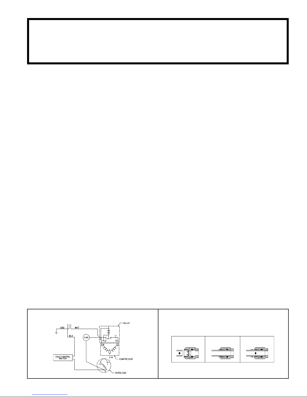
TUBE IS SECURED
IN POSITION
SIMPLY PUSH IN
TUBE TO ATTACH
PUSH IN COLLET
TO RELEASE TUBE
PUSHING TUBE IN BEFORE
PULLING IT OUT HELPS TO
RELEASE TUBE
OPERATION OF QUICK CONNECT FITTINGS
1. Insure proper ventilation. In fully recessed drinking fountains be sure condenser faces louver panel and is
within 1/2" (13 mm) of louver panel when panel is in place.
2. Water inlet is 3/8" (10 mm) O.D. tube connector. Contractor to supply connections as required.
3. Connecting lines to be made of copper. Thoroughly flush all lines to remove all foreign matter before
connecting to cooler.
4. Connect cooler to building supply with a shut-off valve and install a 3/8" (10 mm) water line between the valve
and cooler. Remove burrs from outside of water line. Insert water line into bulkhead union until it reaches a
positive stop, approximately 3/4" (19 mm).
5. Electrical: Make sure power supply is identical in voltage, cycle, and phase to that specified on cooler serial
plate. Never wire the compressor directly to the power supply.
The grounding of electrical equipment such as telephone, computers, etc., to water lines is a common procedure.
This grounding may be in the building, or may occur away from the building. This grounding can cause electrical
feedback into a water chiller, creating an electrolysis which causes a metallic taste or an increase in the metal
content of the water. This condition is avoidable by using the proper materials indicated below. Drain fittings which
are provided by the installer should be plastic to electrically isolate the chiller from the building plumbing system.
Temperature Control: Factory-set for 50°F water (± 5°) under normal conditions. For colder water, adjust screw
on item no. 5.
Ventilation: Cabinet louvers and condenser fins should be periodically cleaned with a brush, air hose, or vacuum
cleaner. Excess dirt or poor ventilation can cause no cold water and compressor cycling on the overload
protector.
Lubrication: Motors are lifetime lubricated.
Actuation of Quick Connect Water Fittings: Cooler is provided with lead-free connectors which utilize an o-ring
seal. To remove tubing from the fittings, relieve water pressure, push in on gray collar while pulling on the
tubing. To insert tubing, push tube straight into fitting until it reaches a positive stop, approximately 3/4.
INSTALLATION
IMPORTANT! INSTALLER PLEASE NOTE:
TROUBLE SHOOTING & MAINTENANCE
START-UP
1. Open supply line valve.
2. Purge all air from all water lines by operating bubbler valve of fountain to which cooler is connected. A steady
stream flow assures that all air is removed.
3. Rotate fan blade to assure proper clearance and free action.
4. Connect to proper electrical power.
WIRING DIAGRAM
ECU8*1A, ECU8*2A, ECU8*3A
97381C (Rev. A - 12/98)
ELKAY MANUFACTURING COMPANY2222 CAMDEN COURTOAK BROOK, IL 60523630.574.8484
FOR PARTS, CONTACT YOUR LOCAL DISTRIBUTOR OR CALL 1.800.323.0620
DESCRIPTION
66505C
50189C
66531C
70841C
31513C
35947C
31039C
35768C
35935C
19037000
101516143550
100806740570
20282C
31490C
70018C
30664C
66202C
66305C
31504C
1
2
3
4
5
6*
7
8
9
10
11
12
13
14
15
16
17
18
19
PART NO.
EVAPORATOR
SHROUD
HEAT EXCHANGER
UNION - BULKHEAD
COLD CONTROL
COMPRESSOR SERV. PAK
OVERLOAD/RELAY ASSY
COVER - RELAY
CAPACITOR
CLIP - COMP MTG
STUD - COMP MTG
GROMMET - COMP MTG
BRACKET - FAN MTG
FAN MOTOR
NUT
FAN BLADE
DRIER
CONDENSER
POWER CORD
ITEM NO.
PARTS LIST
DESCRIPTION
66531C
35763C
35842C
31024C
31430C
31431C
31506C
3
6*
7
14
19
PART NO.
HEAT EXCHANGER (ECU2/3)
COMP SERV. PAK (ECU2)
COMP SERV. PAK (ECU3)
OVERLOAD/RELAY ASSY (ECU2)
FAN MOTOR (ECU2)
FAN MOTOR (ECU3)
POWER CORD (ECU2/3)
ITEM NO.
220/240 - 50/60HZ
1
3
19
25
10, 11, 12
6
13, 14, 15, 16
18
17
*INCLUDES RELAY & OVERLOAD. IF UNDER WARRANTY REPLACE
WITH SAME COMPRESSOR USED IN ORIGINAL ASSEMBLY.
NOTE: ALL CORRESPONDENCE PERTAINING TO ANY OF THE ABOVE
WATER COOLERS OR ORDERS FOR REPAIR PARTS MUST INCLUDE
MODEL NO. AND SERIAL NO. OF COOLER, NAME AND PART NO. OF
REPLACEMENT PART.
7, 8, 9
4