Ellis 9400 User manual

9400
VARIABLE SPEED
DRILL PRESS
OWNER'S
MANUAL
SERIAL NUMBER:
DATE PURCHASED:

EllisSaw.com
2
TABLE OF CONTENTS
POWER FEED DRILL PRESS
Innitely Variable Speed
Model 9400
Important Information
Safety
Drill Specications
Variable Speed Control Box
Torque Range Operation Instructions
Speed & Torque Range Overview
Power Train Overview
Power Train: Depth of Drilled Hole
Drill Chuck and Arbor
Parts List
Maintenance
Troubleshooting
Accessories
Maintenance Log
Overview of Terms
3
4
6
7
8
9
10
11
12
14
18
19
20
22
23
Note: Ellis Manufacturing Co. Inc. reserves the right to make
enhancements to the product at any time. Parts may change or improve,
and the images displayed may not represent the actual product shipped.

3
1.800.383.5547
• Use a 110-Volt, 20 amp, 60 Hz
grounded power circuit.
• No GFCI (Ground Fault Circuit
Interrupter).
• Adapters, extension cords and surge
protectors will prove to be problematic
with the drill press.
GENERAL INFORMATION
• For optimum performance, the Variable Speed
Control Box assembly is preset at the factory (Ellis).
• Adjusting speed and torque (see page 8).
• Lubrication and maintenance (see page 18).
• Adjusting table (see page 13).
• Powered by 110 Volts, the Variable Speed Control
Box (#4830) converts and drives a three-phase,
220-Volt electric motor at variable speeds.
• Needs 220 Volts (#4831).
INSTALLATION INSTRUCTIONS
The Ellis Variable Speed Drill Press is crated and
shipped completely assembled.
• Check for transit damage upon delivery.
• After uncrating, place the drill press on a at, solid
oor within reach of a power source.
• If the drill press rocks, place shims under the base
to remove motion.
• Bolt the machine to the oor using four (4) holes
in base.
• Unpainted surfaces are protected with a lm of
heavy grease.
• Remove grease with mineral spirits.
• Apply a thin coat of oil to machined surfaces.
• Morse Taper Bore must be cleaned of grease
using mineral spirits and by twisting a rag up into
the bore.
Thank you for purchasing the Ellis Model
9400 Drill Press (2HP–110V or 220V).
This machine is suitable for:
• Drilling, Reaming and Tapping:
Metal, Metal Alloys, Plastic, or Wood.
FEATURES
• Three (3) speed ranges controlled by a Variable
Speed (VS) Control Box.
• Three (3) torque ranges by moving a shift handle
with locking feature.
• One switch for forward and reversing direction.
BEFORE USING THIS DRILL PRESS
• Read this manual carefully for operation and
maintenance of this drill press.
• Keep the drill press in good operational condition.
• Keep it clean.
• Do NOT tamper with the wiring or settings—
this will void the warranty.
PROPER ELECTRICAL
INSTALLATION/CONNECTION
IMPORTANT INFORMATION!!
WARNING:

EllisSaw.com
4
GENERAL OPERATING SAFETY
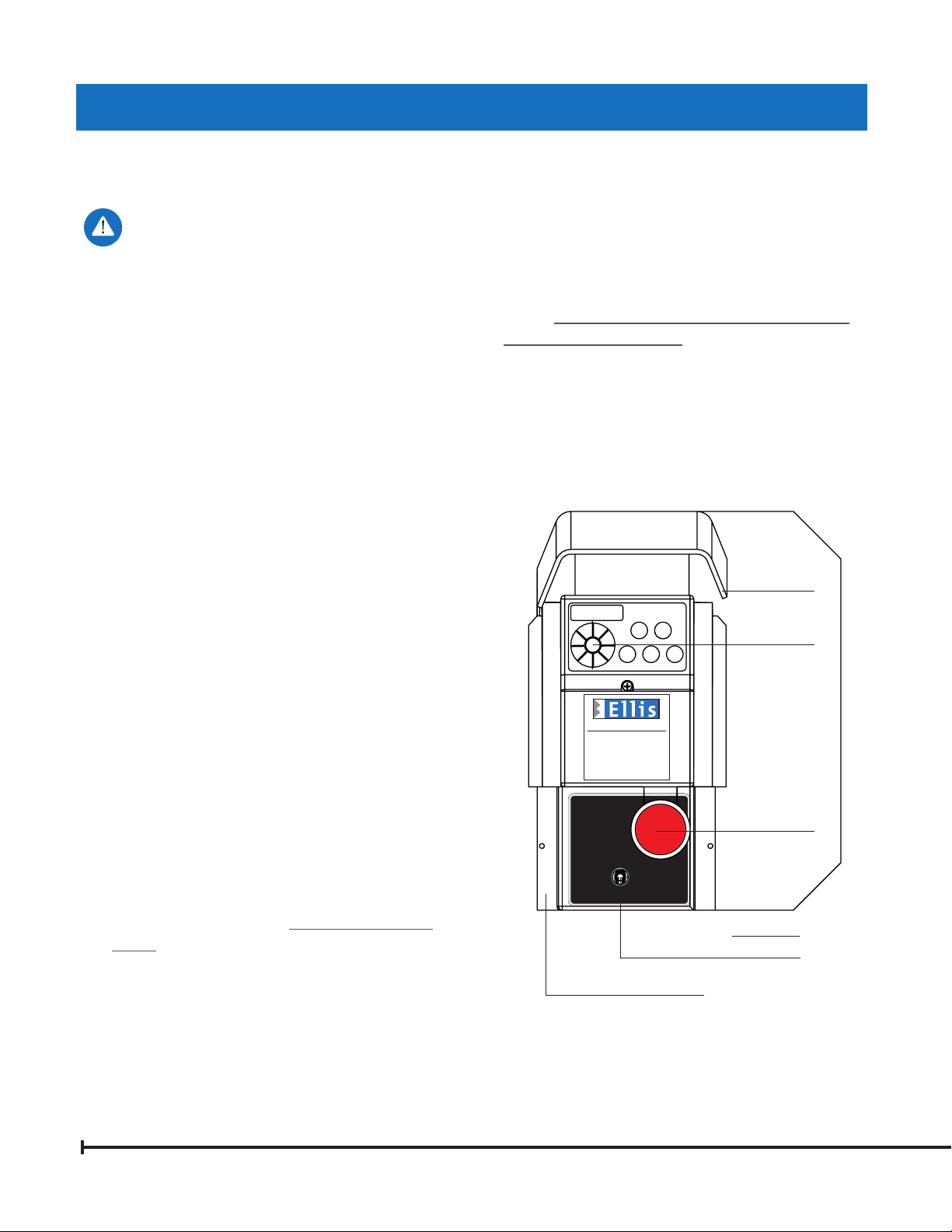
Variable Speed
EMERGENCY STOP BUTTON
stops machine and turns
machine off with time delay.
- flip toggle to direction
of desired rotation.
- flip toggle to center to stop.
5062-1
EMERGENCY
STOP/OFF
STOP
RESET
REVERSE FORWARD
5061-2
WARNING
1. Wear eye protection.
2. Do not wear gloves, a necktie or
loose clothing while working at the
drill press.
3. Clamp workpiece or brace it against
a fixed stop to prevent rotation.
4. Use recommended speeds that are
proper for the drill, workpiece
material and accessories used.
5051-1
(608) 845-6472 • EllisSaw.com
Ellis MFG. CO., INC. • P.O. Box 930219 • Verona, WI 53593
READ INSTRUCTION MANUAL BEFORE
OPERATING THE DRILL PRESS AND
FOLLOW WARNINGS LISTED BELOW
SAFETY AND INFORMATION LABELS
ATTENTION!
Loosen clamp screws prior
to adjusting table height.
5069
HIGH
SPEED
MID-RANGE
TORQUE
HIGH
TORQUE
MUST RUN MOTOR TO SHIFT TORQUE!
ReadandunderstandOwnersManualbefore
operatingthismachine!
5050-1
SAFETY
1. Always wear safety glasses.
2. Do not wear gloves, necktie, loose clothing,
jewelry or other items that may get caught in
moving parts. Long hair should be tied up and
under a cap.
3. Do not hold by hand. Use Safety Drill Press
Vise. Always clamp material to worktable. Utilize
two (2) T-Slots in worktable or base of the drill
press for additional holding points using T-Bolts,
clamps and hold downs. Always use accessories
sold for this machine for accuracy and safety.
4. Use recommended speeds that are proper
for the drill, the material being drilled and
accessories used.
5. Make a habit of removing the chuck key, drift
key and other wrenches after their use.
6. Keep hands and ngers clear of the drill bit
or cutter.
7. Shut off the power by using #4819 Emergency
Stop Button (red in color) before removing or
installing drill bits or cutting tools.
8. Be sure that the head stock and worktable are
securely clamped to the column. Always use
accessories sold for this machine for accuracy
and safety.
9. Be sure the drill bit or cutting tool is securely
clamped in the chuck.
10. Keep cover (of belts and pulleys) in place
and closed.
11. Do not operate the machine beyond its capacity.
12. Maintain the machine regularly, keep it clean,
and keep a maintenance lubrication log.
5050 Shift Speed Label 5069 Attention Label
5062 Operating Label
5051 Warning Label
5061 Forward/Reverse Label
5059 Ellis Logo Label
WARNING
Disconnect Power Cord
From the Wall Outlet
Before Any Maintenance!

5
1.800.383.5547
Disconnect the power cord from the
wall outlet before any maintenance.
VARIABLE SPEED CONTROL BOX
1. Do not open the Variable Speed (VS) Control
Box. Tampering with the wiring or setting
will void the warranty. The circuit board is
not eld repairable. Do not touch or adjust
anything without calling Ellis Manufacturing Co.
for instructions. The circuits in the VS Control Box
are not isolated. Elements of the circuit board are
at 230 Volts. Direct contact with these circuits can
cause serious injury.
2. The control circuit is not fail-safe. A disconnect at
the wall outlet is the only way to reliably disable
the VS Control Box.
3. While power is ON or for some time after power-
OFF, do not touch the VS Control Box since the
VS Control box will be extremely hot. Doing so
can cause burns.
4. If you have problems with the Variable Speed
Control Box, contact the factory M–F,
7:30 am – 4:00 pm CST.
SAFETY
WARNING:
EMERGENCY
STOP/OFF
STOP
RESET
REVERSE FORWARD
5061-2
Variable Speed
EMERGENCY STOP BUTTON
stops machine and turns
machine off with time delay.
- flip toggle to direction
of desired rotation.
- flip toggle to center to stop.
5062-1 4819
Red
Emergency
Stop Button
8154
Control
Bracket
4767 Toggle Switch
8151 Control Box Base
Speed
Dial
Variable Speed Control Box
DO NOT WEAR:
JEWELRY, LOOSE CLOTHING, GLOVES
TIE BACK LONG HAIR WHEN OPERATING THIS EQUIPMENT
FWD–REV

EllisSaw.com
6
DRILL SPECIFICATIONS
Motor Specications
Horsepower 2 (1.5kW)
Voltage 110 V
Hertz 60
Amp 6.8
Duty S1
Phase 3
Type Induction B Grade
Machine Specications
Drive Belt and Variable Speed Control
Maximum Drill Diameter 1.062" Steel; 1.25" Cast Iron
Tapping Capacity 3/4" – 10 NC
T-Slots Two (2) 0.625" Slots on Worktable and Base
Overall Size of Table 15.88" x 17.88"
Table Machined Surface 15.88" x 17.88"
Overall Size of Base 16.38" x 26.62"
Base Machined Surface 11.80" x 12.60"
Power Feed Rate per Spindle Revolution 0.004"
Diameter of Column 4"
Recessed Diameter of Quill 3"
Exposed Diameter of Quill 3.75"
Maximum Spindle Travel 5.375"
Spindle Inner Taper Morse Taper #3 (MT3)
Spindle Speed Variable; 0–1200 rpm
Spindle to Table 27.25"
Maximum Distance Spindle Nose to Base Surface 46.25"
Drills to Center 18.12"
Net Weight 677 lbs.
Overall Size 20" width x 29" depth x 69.5" height
DRILL PRESS ACCESSORIES
Increase Accuracy and Performance
See pages 20–21
TC18-2
图号
S
1:1
图号
更改文件号
设 计
校 对
审 核
工 艺
标准化
审 定
日 期
图 样 标 记 数 量 重 量 比 例
共 张
第 张
江苏高邮市力博机床附件厂
借(通)用件登记
描 图
描 校
旧底图总号
底图总号
签 字
日 期
标记
处数
签 字
日 期
MILLING TABLE DRILL CHUCK 6.25" DRILL PRESS VICE POLYCARBONATE
CHUCK GUARD
T-SLOT BOLTS
6.5寸快速钳
图号
S
1:1
图号
更改文件号
设 计
校 对
审 核
工 艺
标准化
审 定
日 期
图 样 标 记 数 量 重 量 比 例
共 张
第 张
江苏高邮市力博机床附件厂
借(通)用件登记
描 图
描 校
旧底图总号
底图总号
签 字
日 期
标记
处数
签 字
日 期
A A
B B
2
2
1
1
DO NOT SCALE DRAWING
Drill Press Guard asm
SHEET 1 OF 1
UNLESS OTHERWISE SPECIFIED:
SCALE: 1:5
WEIGHT:
REV
DWG. NO.
A
SIZE
TITLE:
NAME
DATE
COMMENTS:
Q.A.
MFG APPR.
ENG APPR.
CHECKED
DRAWN
FINISH
MATERIAL
INTERPRET GEOMETRIC
TOLERANCING PER:
DIMENSIONS ARE IN INCHES
TOLERANCES:
FRACTIONAL
ANGULAR: MACH
BEND
TWO PLACE DECIMAL
THREE PLACE DECIMAL
APPLICATION
USED ON
NEXT ASSY
PROPRIETARY AND CONFIDENTIAL
THE INFORMATION CONTAINED IN THIS
DRAWING IS THE SOLE PROPERTY OF
<INSERT COMPANY NAME HERE>. ANY
REPRODUCTION IN PART OR AS A WHOLE
WITHOUT THE WRITTEN PERMISSION OF
<INSERT COMPANY NAME HERE> IS
PROHIBITED.

7
1.800.383.5547
VARIABLE SPEED CONTROL BOX
SET UP
Important: Do not plug into
a GFCI circuit.
It is highly recommended to shift into High Torque
using the Torque Bolt Range ASSY. (For larger
diameter drills, tapping and hole saws, see page 8
for more information.)
1. Start Turn the Red Emergency Stop Button
clockwise (in the direction of the arrows) so that
the button will pop out and the read out window
will light up. Flip the Forward/Reverse switch to
the reset position, then to the desired direction of
forward or reverse.
2. Speed Change The black dial in the upper
left hand corner regulates the spindle speed.
(120 HZ = 100% of the spindle speed)
See page 9 for RPM matrix. It works in both
the forward and reverse mode.
3. Forward Toggle Switch Position (#4767)
Use the Forward Switch Position for standard
drilling, tapping and hole saw cutting.
4. Reverse Toggle Switch Position (#4767)
Use the Reverse Switch Position to retract a tap
or to tap a left hand thread. Keep downward
pressure on the Feed Handle when backing a tap
out of the work piece.
5. Stop/Reset Toggle Switch Position
(#4767) This setting stops the motor from either
forward or reverse rotation. Use this as the Stop
Switch while operating the drill press. Move the
Toggle Switch to reset position after a power
outage or after hitting the Red Emergency Stop
Button (#4819).
6. Stop The Red Emergency Stop Button stops
the machine and automatically disconnects
the machine from electrical power after a time
delay of about twenty seconds. Use this as
the Power Off switch at the end of the
work day.
NOTE: Avoid stalling the spindle and stopping
the motor under power. Turn Power off
immediately in a stalled motor condition. Clear
the jam mechanically. Repeated stalling abuse
is detectable and can lead to voiding
the warranty.
Variable Speed Control Box
EMERGENCY
STOP/OFF
STOP
RESET
REVERSE FORWARD
5061-2
Variable Speed
EMERGENCY STOP BUTTON
stops machine and turns
machine off with time delay.
- flip toggle to direction
of desired rotation.
- flip toggle to center to stop.
5062-1 4819
Red
Emergency
Stop Button
8154
Control
Bracket
4767 Toggle Switch
8151 Control Box Base
Speed
Dial
FWD–REV

EllisSaw.com
8
InIn
11
11
22
//
2 in2 in
11
2 i2 inn
22
//
0
0
1/2 in1/2 in
5 i5 inn
HIGH
SPEED
MID-RANGE
TORQUE
HIGH
TORQUE
MUST RUN MOTOR TO SHIFT TORQUE!
ReadandunderstandOwnersManualbefore
operatingthismachine!
5050-1
OPERATING INSTRUCTIONS
1. Turn on the drill press and run it at moderate speed.
NOTE: The motor must be moving at a
moderate speed to change the torque range
selection.
2. Grasp the Shift Handle that is attached to the
Motor Mounting Plate and raise it to a horizontal
position with your right hand. See Figure A.
3. Push forward on the Shift Handle just enough to
relieve the pressure on the Torque Bolt Range ASSY.
Refer to Figure B and C.
4. Loosen the Range Knob and raise it out of
the position locking slot. See Figure C.
5. Push the Motor and the Torque Bolt Range ASSY
forward to reduce the spindle speed and increase
the torque. Moving the Torque Bolt Range ASSY and
the motor in the opposite direction will increase the
spindle speed.
NOTE: Make sure that the Range Knob is fully seated
in the locking slot when in the MID-RANGE TORQUE or
HIGH TORQUE positions.
MACHINE SPEED CONTROL
CAPABILITY
NOTE: The complete speed variation from zero to the
maximum of each range is made electronically using the
speed control dial on the Ellis Variable Speed Control
Box (+/- 10%).
• High Speed, 0 to approximately 1265 RPM range.
This is the range best suited for small drills.
• Mid-Range Torque, 0 to approximately 930 RPM
speed. This is the general purpose drilling range.
• High Torque, 0 to approximately 570 RPM. This
range provides the highest torque. Use it for larger
drills and taps and for cutting large holes using
Hole Saws.
Figure C
Figure B
Figure A
TORQUE RANGE OPERATION
Shift Handle
Torque Bolt
Range
ASSY
(p. 9)
Range Knob

9
1.800.383.5547
Spindle RPM
Torque
Range
Position
VS Control Box Frequency – Hz
120 105 90 75 60 45 30 20 15 10
High Speed 1265 1110 950 792 633 473 317 209 156 102
Mid-Range 930 820 705 585 465 350 233 153 115 77
High Torque 570 501 428 358 285 215 143 94 71 46
SPEED & TORQUE RANGE OVERVIEW
HIGH
SPEED
MID-RANGE
TORQUE
HIGH
TORQUE
MUST RUN MOTOR TO SHIFT TORQUE!
ReadandunderstandOwnersManualbefore
operatingthismachine!
5050-1
8434
Spindle Pulley
8101
Torque Bolt Range ASSY 8115
Shift Handle
4647
Motor
8437 Feed Pulley & Clutch ASSY 8495 Middle Sheave ASSY 4646
Variable
Speed Pulley
SPINDLE SPEED
The motor (#4647) drives the middle sheave (#8495) and the spindle pulley (#8434) by V-Belts. The spindle pulley
drives the spindle and the taper sleeve. The spindle speed is variable by means of the Variable Speed Control Box
and/or with Shift Handle. Forward and reverse rotation of the spindle is selected on the VS Control Box Panel.
If you have any problems, call the factory.

EllisSaw.com
10
0
1/2 in
5 in
POWER FEED AND MANUAL FEED
Manual Feed is accomplished by turning the Handle Hub (#8439) with either Feed Handle (#8474) located on the
right side of Drill Press Head.
Power Feed is accomplished by loosening Thumbscrew (#8383) on Handle Hub (#8439). To engage Power Feed, pull
either Feed Handle (#8474) to the right, away from Head. To stop Power Feed, push either Feed Handle (#8474) to
the left towards the head. To disable Power Feed, tighten Thumbscrew (#8383).
0
1/2 in
5 in
In
1
1
2
/
2 in
1
2 in
2
/
0
1/2 in
5 in
POWER TRAIN OVERVIEW
Manual Feed Position Power Feed Position
8440 Dial
8439 Handle Hub
8474 Feed Handle
8383 Thumbscrew ASSY
8472 Locking Handle

11
1.800.383.5547
OVERLOAD CLUTCH
1. The Drill Press is equipped with a power feed
overload clutch.
2. The overload clutch protects the power train from
damage. Cause: spindle speed is too high.
3. When you hear a clicking noise, the overload
clutch is working, stopping power from turning
drill bit or cutter.
4. Reduce spindle speed when this occurs.
5. The overload clutch is adjustable.
6. There are two (2) adjustment screws in the pulley
groove at 180 degrees from each other.
See Figure #8437.
7. To set maximum torque: turn each adjustment
screw (clockwise) until tight, then loosen (counter-
clockwise) two full (360 degrees) rotations.
NOTE: Do not tighten the screws too far
because a solid spring cannot let the ball escape
from the groove in the shaft. In this case, the
overload clutch would be rendered useless and
damage will occur.
Adjustment Screw Spring Steel Ball
Feed Pulley
Steel Ball Adjustment ScrewSpring
8437 — Feed Pulley with
Overload Clutch ASSY
POWER TRAIN: DEPTH OF DRILLED HOLE
"TO SET" DEPTH OF DRILLED HOLE
1. Loosen Locking Handle (#8472) on Handle
Hub (#8439).
2. Lower drill bit to desired depth by turning
Feed Handles (#8474).
3. Hold Feed Handles in place.
4. Turn the dial (#8440) CCW (counter-clockwise)
until it stops.
5. Retighten Locking Handle (#8472).
6. Drill sample hole.
7. Check the depth.
NOTE: When drilling holes through materials:
8. Place material in Drill Press Vise. Vise holds
material up off the worktable.
OR
9. Place wood or metal under materials
being drilled to prevent drilling into
the worktable.

EllisSaw.com
12
INSTALLING DRILL CHUCK
AND ARBOR (FIGURE A)
The Ellis 9400 Drill Press comes with a
Morse Taper #3 (MT3).
1. Clean the inside taper in the drill press spindle.
2. Clean the outside of the tapers on the drills
and chucks.
3. To insert the MT3 arbor into the spindle:
a. Insert arbor in hole and turn until taper falls into
slot. Push up rmly or tap with soft hammer.
b. Place a block of wood on the table under drill
or chuck (#8649).
c. Using Feed Handles, press down to seat arbor
into spindle of drill press.
REMOVING DRILL CHUCK
AND ARBOR (FIGURE B)
1. Lower the Drill Press Spindle until the slot is visible.
2. Using locking handle (#8472) and dial (#8440),
rotate dial CW (clockwise) until it stops (p. 10).
3. Tighten locking handle (#8472)—this holds spindle
down in place.
4. Turn drill chuck or drill (by hand) until
slots align.
5. Insert drift key (#8073) into slot.
6. Hold chuck or drill with one hand while tapping
on drift key with hammer.
7. Drill or chuck will come out of slot.
DRILL SPEEDS AND USAGE
The speed at which the drill has to rotate for efcient
cutting depends on the type of material being worked
and the diameter of the drill.
• Apply cutting oil (uid) to the drill bit. When drilling
deep holes, retract the drill bit often to remove chips.
• Use a low Spindle Speed and High Torque Range for
tapping a threaded hole.
• Use a heavy oil or thread cutting uid to lubricate the tap.
• Reverse the spindle rotation with the reverse switch
on the VS Control Box to retract the tap.
TIGHTENING CHUCK
The Ellis 3/4" drill chuck (#8649) is designed to
hold drill bits and taps securely. Adjust the chuck by
rotating the sleeve clockwise until it is open more than
the size of the shaft. Hold the bit in place and turn the
sleeve counter-clockwise until the jaws of the chuck
hold the bit in place. Be sure to check that the bit is
installed straight. Locate the three (3) pilot holes on
the chuck body. Use the 11-point key and insert and
tighten each of the three (3) pilot holes under even
and rm pressure.
ROTATING, ELEVATING AND
CLAMPING THE TABLE (FIGURE C)
The worktable can rotate 360 degrees and move up
and down on the column. Loosen both column
clamp screws (#8407), rotate the table to the
required position, elevate the table by means of the
elevating handle (#8406). Then, tighten both clamp
screws again. (See Figure C)
DRILL CHUCK AND ARBOR
Damage will occur to internal table gear
components if column clamp screws are not
loosened prior to elevating table.
WARNING:
MT3
JT4
4981 — Arbor

13
1.800.383.5547
Figure A – Inserting
Figure C
Figure B – Removing
Drill Chuck and Arbor Attachment
Elevating, Rotating and Clamping the Table
Loosen column clamp
screws before moving
table otherwise
damage will occur.
WARNING:
8407 Column Clamp Screw
8406 Elevating Handle
8486 Revolving Handle
8649 Chuck
8073 Drift Key
Quill Slot
Align slots

EllisSaw.com
14
Number
Part
Number Name
18437 Feed Pulley & Clutch ASSY
24938 V-Belt Upper, Power Feed
38436 Nut (2)
48434 Spindle Pulley
58433 Worm Base
68432 Spindle Shaft
78382 Cover Knob ASSY
88431 Cover
98430 Spacer
10 8428 Sight Window
11 8429 Spring & Cover
12 8423 Spring Cap
13 8422 Shaft Base
14 8419 Head Stock
15 8418 Gear Shaft
16 8154 Control Bracket
17 4830 VS Control Box (110V)
18 4831 VS Control Box (220V)
19 4819 Red Emergency Stop Button
20 8151 Control Box Base
21 4767 Fwd-Rev. Toggle Switch
22 8417 Turbo Worm Gear
23 8416 Counter Block
24 8415 Quill
25 8414 Worm Cover
26 8413 Thrust Plate
27 8412 Nut
28 8440 Dial (Standard Measure)
29 8439 Handle Hub
30 8411 Spindle
31 4939 V-Belt Lower, Front Drive
32 8495 Middle Sheave ASSY
33 8476 Swivel Base Weldment
34 8081 Set Screw
35 4646 Variable Speed Pulley
Number
Part
Number Name
36 4943 V-Belt, Rear Drive
37 4647 Motor, 2HP (1.5KW)
38 8475 Motor Mounting Plate ASSY
39 8121 Motor Fan Cover
40 8122 Motor Junction Box Cover
(not pictured)
41 8115 Shift Handle
42 8101 Torque Bolt Range ASSY
43 8452 Worm Cover
44 4487 Ball Bearing
45 8461 Bevel Gear
46 8453 Worm, Double Thread
47 8441 Key
48 8454 Shim Plate
49 8455 Turbo Gear
50 8457 Transmission Shaft
51 8458 Gear
52 8459 Transmission Base
53 4487 Ball Bearing
54 8461 Bevel Gear
55 8380 Hub & Pawl ASSY
56 8465 Plate
57 8450 Power Feed Unit ASSY
58 8467 Block
59 8468 Power Feed Label
60 8469 Manual Feed Label
61 8470 Worm Housing
62 4487 Ball Bearing
63 8471 Lock Screw
64 8472 Locking Handle
65 8473 Power Feed Bolt ASSY
66 8383 Thumbscrew ASSY
67 8474 Feed Handle
68 8481 Handle Grip
HEAD ASSEMBLY (For Bearings See Page 17)
PARTS LIST
NOTE: When ordering parts, please provide the serial number located on the Drill Press head.

15
1.800.383.5547
25
22
19
20
21
24
27
28
29
14
9
4
8
3
30
6
7
5
1
232
33
34
35
39
41
42
40(not pictured)
37
38
36
31
15
26
23
10
13
16
17
18
12
11
43
45
46
47
48
49
50
51
52
53
54
55
56
57
58
59
60
61
62
63
64
65
66
67
44
68
HEAD ASSEMBLY PARTS EXPLOSION

EllisSaw.com
16
WORKTABLE AND BASE ASSEMBLY
Column Assembly Parts Explosion
Number
Part
Number Name
18401 Column Base
28403 Rack Gear
38404 Column
48486 Revolving Handle
58406 Elevating Handle
68407 Column Clamp Screw
78077 Column Ring
88410 Worktable
98442 Table Bracket
10 8443 Table Clamp Screw
11 8490 Worm Drive ASSY
(Includes Axis Pin,
Worm, Gear)
12 8492 Table Bracket ASSY
(Includes 8442 & 8490)
1
2
3
5
6
7
8
9
10
11
4
PARTS LIST (CONT.)
(worm)
(pin)
(gear)
12
Note: When ordering parts, please provide the
serial number located on the Drill Press head.

17
1.800.383.5547
PARTS LIST (CONT.)
The chart below identies the bearings in the various locations. The Ellis Part Number is required for replacement orders.
Number
Part
Number Bearing Type Location Size Quantity
14490 Deep Groove Spline-Taper Sleeve 45 x 75 x 16 2
24491 Deep Groove Quill 30 x 55 x 13 1
34492 Ball Thrust Quill 35 x 52 x 12 1
44493 Deep Groove Quill 35 x 72 x 17 1
58495 Deep Groove Middle Sheave ASSY 17 x 40 x 12 2
64495 Deep Groove Single Thread Worm 20 x 42 x 12 1
74495 Deep Groove Single Thread Worm 20 x 42 x 12 1
1
2
7
6
5
4
3
8434 Spindle Pulley
8437 Feed Pulley with
Overload Clutch ASSY
8495 Middle
Sheave ASSY
Spindle
BEARING LOCATION
Note: When ordering parts, please provide the serial number located on the Drill Press head.

EllisSaw.com
18
Grease
Fittings
LUBRICATION
The Power Feed Unit Box has two (2) grease ttings.
It is important that the operator grease the machine
frequently. Use Lithium Grease. Do not mix
synthetic and mineral based grease.
Location Suggested
Lubricant Frequency
Grease Fittings
(2)
Lithium Grease
N.L.G.I. #2
Monthly or after
25–30 hours
of use
LUBRICATION SCHEDULE
MAINTENANCE
STANDARD MAINTENANCE
• Keep table and sliding parts clean of dirt and chips.
• Every three months lower the quill, wipe clean and
oil lightly. If raising the table becomes difcult,
clean and wipe the column with light machine oil.
• The ball bearings in the motor, quill and V-Belt
pulleys are sealed bearings.
• Keep the cooling ns of the VS Control Box and the
motor clean and free of dirt and dust.
• Check V-Belts for tension and excessive wear.

19
1.800.383.5547
Problem Probable Cause Remedy
Motor does not run
Power cord not plugged into source Plug into receptacle
VS Control Box not "ON" Push and turn Emergency Stop Button
Speed Dial in "0" position Turn dial counterclockwise for more speed
Motor is too hot—heat switch tripped Wait for motor to cool off
Power cord plugged into GFCI
protected outlet
Plug into an unprotected outlet, preferably
a dedicated circuit of 20 amp, 115 VAC
Power cord not plugged into correct
outlet
Power cord of a 115V single phase machine
has to be plugged into a 115V outlet. A
cord of a 230 single phase machine has to
be plugged into a 230V outlet.
Noisy Operation
Incorrect belt tension Adjust tension
Loose spindle or motor pulley Tighten set screw #8081
Belt is too tight Reduce belt tension
Spindle bearing is worn Replace spindle ball bearing
Spindle not moving up Return Spring may be broken or
Pawl Assembly may be broken.
Replace spiral-spring #8429 or
replace Pawl Assembly #8380.
Drill bit smokes
or is burnt
Needs lubrication Lubricate with cutting uid
Drill is running in reverse Change motor rotation
Dull drill bit Sharpen or replace drill bit
Incorrect speed Change speed
Chips are not coming out of hole Retract drill bit frequently to clear out chips
Excessive Drill Run Out
Bent drill Replace drill
Chuck jaws not clamping evenly Install drill correctly
Worn spindle bearings Replace ball bearings
No Power Feed
Worm gear is worn Replace worm gear
Overload protection device not working Tighten springs with adjustment screws
Pawl clutch is worn Replace Hub and Pawl Assembly #8380
Feed belt is sliding Tighten belt
Feed Handles do not move sideways Loosen thumbscrew #8383
Hole Depth Not Correct Depth dial not clamped Tighten dial lock
Worm gear or quill is worn Replace gear
Drill Not Rotating Taper on chuck slips in spindle
Remove grease and oil from inside taper
bore in spindle and outside of taper on
chuck. Use mineral spirits.
Spindle Not Rotating
in Correct Rotation
Switch on VS Control Box—may not be
in the correct position
Use forward switch for standard drilling and
cutting. Use reverse switch to retract a tap
or tapping for left-hand threads.
TROUBLESHOOTING

EllisSaw.com
20
TC18-2
图号
S
1:1
图号
更改文件号
设 计
校 对
审 核
工 艺
标准化
审 定
日 期
图 样 标 记 数 量 重 量 比 例
共 张
第 张
江苏高邮市力博机床附件厂
借(通)用件登记
描 图
描 校
旧底图总号
底图总号
签 字
日 期
标记
处数
签 字
日 期
MILLING TABLE
The 9400 is a drill press designed for drilling
and tapping. It can provide support for those
quick and light milling jobs and is heavy, precise
and accurate.
The JT4 drill chuck is designed for heavy-duty drilling
applications. The chuck and arbor is ground with high
precision for accuracy and efciency. For best results,
tighten the chuck using ALL 3 chuck pilot holes.
Milling Table Specications
Part # 1003
Action Screw with ball bearings
X Travel 10.63"
Y Travel 4.72"
Cross Travel 7.5"
Longitudinal Travel 11"
Table Length 18.62"
Table Width 6.14"
Base Length 12"
Base Width 8.19"
Height 5.28"
Longitudinal T-Slots Two (2)
Weight 62 lbs
Drill Chuck Specications
Part # 8649
Description
Includes: Drill Chuck
(8649), Arbor (4981),
11 Point Key (8650)
Capacity 1/8"–3/4"
Chuck Taper JT4
Arbor Taper MT3 / JT4
Weight 5.78 lbs
DRILL CHUCK & ARBOR 8649
8650
8649
4981
ACCESSORIES
MT3
JT4
Other manuals for 9400
1
Table of contents
Other Ellis Power Tools manuals
Popular Power Tools manuals by other brands

BASETech
BASETech 1553058 operating instructions

Chauvin Arnoux
Chauvin Arnoux B102 user manual

Arbortech
Arbortech MINI CARVER MIN.FG.600.60 Owner's instruction manual

Zionair
Zionair SK5B Assembly and user instructions

Radio Shack
Radio Shack 20W Soldering Starter Kit user guide

Black & Decker
Black & Decker JS650L instruction manual